Table of Contents
Advertisement
OPERATOR'S MANUAL
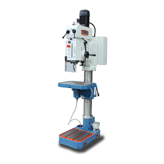
GEAR DRIVEN DRILL PRESS
MODEL: DP-1850G
Baileigh Industrial, Inc.
P.O. Box 531
Manitowoc, WI 54221-0531
Phone: 920.684.4990
Fax: 920.684.3944
sales@baileigh.com
REPRODUCTION OF THIS MANUAL IN ANY FORM WITHOUT WRITTEN APPROVAL OF BAILEIGH INDUSTRIAL, INC.
IS PROHIBITED. Baileigh Industrial, Inc. does not assume and hereby disclaims any liability for any damage or loss
caused by an omission or error in this Operator's Manual, resulting from accident, negligence, or other occurrence.
Rev. 04/2018
© 2018 Baileigh Industrial, Inc.
Advertisement
Table of Contents

Related Manuals for Baileigh Industrial DP-1850G


Summary of Contents for Baileigh Industrial DP-1850G
- Page 1 REPRODUCTION OF THIS MANUAL IN ANY FORM WITHOUT WRITTEN APPROVAL OF BAILEIGH INDUSTRIAL, INC. IS PROHIBITED. Baileigh Industrial, Inc. does not assume and hereby disclaims any liability for any damage or loss caused by an omission or error in this Operator’s Manual, resulting from accident, negligence, or other occurrence.
-
Page 2: Table Of Contents
Table of Contents THANK YOU & WARRANTY ..................1 INTRODUCTION ......................3 GENERAL NOTES ......................3 SAFETY INSTRUCTIONS ....................4 SAFETY PRECAUTIONS ....................6 Dear Valued Customer: ....................6 TECHNICAL SUPPORT ....................8 TECHNICAL SPECIFICATIONS ..................9 UNPACKING AND CHECKING CONTENTS ..............10 Cleaning ........................ - Page 3 COLUMN / BASE PARTS DIAGRAM ................42 Column / Base Parts List ................... 43 ELECTRICAL SCHEMATIC ..................45 ELECTRICAL COMPONENTS ..................47 ELECTRICAL COMPONENT LOCATION ..............48...
-
Page 4: Thank You & Warranty
THANK YOU & WARRANTY Thank you for your purchase of a machine from Baileigh Industrial. We hope that you find it productive and useful to you for a long time to come. Inspection & Acceptance. Buyer shall inspect all Goods within ten (10) days after receipt thereof. Buyer’s payment shall constitute final acceptance of the Goods and shall act as a waiver of the Buyer’s rights to inspect or... - Page 5 • A 30% re-stocking fee applies to all returns. Baileigh Industrial makes every effort to ensure that our posted specifications, images, pricing and product availability are as correct and timely as possible. We apologize for any discrepancies that may occur. Baileigh Industrial reserves the right to make any and all changes deemed necessary in the course of business including but not limited to pricing, product specifications, quantities, and product availability.
-
Page 6: Introduction
After receiving your equipment remove the protective container. Do a complete visual inspection, and if damage is noted, photograph it for insurance claims and contact your carrier at once, requesting inspection. Also contact Baileigh Industrial and inform them of the unexpected occurrence. Temporarily suspend installation. -
Page 7: Safety Instructions
IMPORTANT PLEASE READ THIS OPERATORS MANUAL CAREFULLY It contains important safety information, instructions, and necessary operating procedures. The continual observance of these procedures will help increase your production and extend the life of the equipment. SAFETY INSTRUCTIONS LEARN TO RECOGNIZE SAFETY INFORMATION This is the safety alert symbol. - Page 8 SAVE THESE INSTRUCTIONS. Refer to them often and use them to instruct others. PROTECT EYES Wear safety glasses or suitable eye protection when working on or around machinery. PROTECT AGAINST NOISE Prolonged exposure to loud noise can cause impairment or loss of hearing.
-
Page 9: Safety Precautions
EMERGENCY STOP BUTTON In the event of incorrect operation or dangerous conditions, the machine can be stopped immediately by pressing the E-STOP button. Twist the emergency stop button clockwise (cw) to reset. Note: Resetting the E- Stop will not start the machine. SAFETY PRECAUTIONS Metal working can be dangerous if safe and proper operating procedures are not followed. - Page 10 3. Remove any adjusting tools. Before operating the machine, make sure any adjusting tools have been removed. 4. Never use the drill press without the swing-away safety guard. 5. Keep work area clean. Cluttered areas invite injuries. 6. Overloading machine. By overloading the machine you may cause injury from flying parts. DO NOT exceed the specified machine capacities.
-
Page 11: Technical Support
21. Turn off power before checking, cleaning, or replacing parts. 22. Be sure all equipment is properly installed and grounded according to national, state, and local codes. 23. Keep all cords dry and free from grease and oil. 24. Inspect power and control cables periodically. Replace if damaged or bare wires are exposed. -
Page 12: Technical Specifications
TECHNICAL SPECIFICATIONS 1.57” (40mm) Maximum Drill Capacity 0.875” (22.2mm) Maximum Tapping Capacity 13.375” (339.7mm) Depth (Spindle center to Column center) 26.75” (680mm) Swing 4” (101.6mm) Minimum Distance from Spindle to Table Maximum Distance from Spindle to Table 24” (609.6mm) 47” (1194mm) Maximum Distance from Spindle to Base 2.75”... -
Page 13: Unpacking And Checking Contents
UNPACKING AND CHECKING CONTENTS Your Baileigh machine is shipped complete. Separate all parts from the packing material and check each item carefully. Make certain all items are accounted for before discarding any packing material. WARNING: SUFFOCATION HAZARD! Immediately discard any plastic bags and packing materials to eliminate choking and suffocation hazards to children and animals. -
Page 14: Transporting And Lifting
TRANSPORTING AND LIFTING NOTICE: Lifting and carrying operations should be carried out by skilled workers, such as a truck operator, crane operator, etc. If a crane is used to lift the machine, attach the lifting chain carefully, making sure the machine is well balanced. Follow these guidelines when lifting with truck or trolley: •... -
Page 15: Installation
INSTALLATION IMPORTANT: Consider the following when looking for a suitable location to place the machine: • Overall weight of the machine. • Weight of material being processed. • Sizes of material to be processed through the machine. • Space needed for auxiliary stands, work tables, or other machinery. •... -
Page 17: Oil Filling
Oil Filling The gear box incorporates an oil pump to lubricate the gears. The machine is supplied without oil for transport reasons. 1. Remove upper plug. 2. Using a funnel, add oil until the oil level is between the red mark (center) and the top of the sight glass. Approximately 2.6qt. -
Page 18: Coolant
4. Install the motor into the drill head. Align the motor with the flat of the mounting plate toward the front of the drill head and the motor conduit box toward the left side of the drill head. 5. Install the four cap screws and lock washers and tighten the motor into the drill head. -
Page 19: Electrical
ELECTRICAL WARNING: Baileigh Industrial is not responsible for any damage caused by wiring up to an alternative 3-phase power source other than direct 3-phase. If you are using an alternate power source, consult a certified electrician or contact Baileigh Industrial prior to energizing the machine. - Page 20 WARNING: In all cases, make certain the receptacle in question is properly grounded. If you are not sure, have a qualified electrician check the receptacle • Improper connection of the equipment-grounding conductor can result in risk of electric shock. The conductor with insulation having an outer surface that is green with or without yellow stripes is the equipment-grounding conductor.
- Page 21 7. When the main disconnect is turned on does the Stop button (A) illuminate? Yes, Power is connected. No, Check power connections. 8. Does the rotation of the spindle match the rotation as indicated by the switch? a. Press the upper Clockwise rotation switch (B).
-
Page 22: Getting To Know Your Machine
GETTING TO KNOW YOUR MACHINE... - Page 23 Item Description Table Elevation Crank Handle, for lifting and lowering the work table. Chuck Guard, To cover the drill area during operation to restrict and prevent chips and material from being ejected toward the operator. Quill Feed Handle, To lower and raise the quill during operation. Includes the clutch engagement switches for power down feed when set and selected.
-
Page 24: Contents Of Tool Box
Contents of Tool Box Item Description Tool Box Drill Chuck Chuck Key Drill Chuck Adaptor Drill Shank Adaptors Taper Wedges Open End Wrench (21x24mm) Fuse (10A, 5A, 3A, 1A) -
Page 25: Setup And Operation
SETUP and OPERATION CAUTION: Always wear proper eye protection with side shields, safety footwear, and leather gloves to protect from burrs and sharp edges. Operation Panel Power Feed Clutch Switch (3) Coolant Pump Switch Emergency Stop Taping Switch Clockwise Switch Main Power Disconnect Stop Switch... -
Page 26: Drill Protection Guard
Do not ever use tools which were not designed to be used in a drilling machine and that have been adapted. A drilling machine can also perform other machining operations a part from the drilling, such as tapping, reaming, chamfering, punch marking, countersinking, spot facing, to perform such operations, it is necessary to have appropriate tools, specially designed for this sort of jobs. -
Page 27: Feeds Selector
Feeds Selector This gear (A) and switch(es) (C) combination is used to select the desired amount of feed per revolution of the spindle and then when to engage or disengage the function. Important: DO NOT change spindle direction until the spindle has stopped completely. Select the feed rate with the feed rate handle (A), matching the shift lever position to the picture on the feed rate chart to set the desired feed rate. - Page 28 • When the feed clutch engages, the green indicator light (D) above the tachometer will turn on and the clutch will start to pull the feed handle. • Release the handle and the switch and allow the clutch to provide the down force. •...
-
Page 29: Tool Attaching
Tool Attaching The tools generally used in this machine will have parallel or taper shanks. Drill holders are normally used to fix to the main spindle of the machine the parallel shank tools. This fixing device is used for small drill diameters (maximum up to diameter 5/8” [16mm]). Bigger diameter drills, usually have taper shank of Morse taper (the ones of smaller diameters to 5/8”... -
Page 30: Automatic Tool Ejector
Automatic Tool Ejector NOTICE: DO NOT leave the removal knob engaged during normal operation. Doing so will cause the tool to become dislodged from the spindle! Normal operation the knob will be pressed in. It will be out only for tool removal! To remove tool from the spindle, perform the following operations: 1. -
Page 31: Tapping
Tapping NOTICE: This is a conventional drill, not a special purpose machine, therefore frequent tapping jobs will wear the motor and gears. Temperature of motor will be increased quickly when tapping due to low motor RPM and frequently motor direction be changed. Therefore, rapid and continuous tapping shall be avoided. -
Page 32: Setting The Depth Stop
Setting the Depth Stop This machine has some built-in control stops that activate when either the bottom or top quill travel limits are reached. Their functions include stop drilling, reverse tapping, or return the drill bit to the start height. 1. -
Page 33: Lubrication And Maintenance
LUBRICATION AND MAINTENANCE WARNING: Make sure the electrical disconnect is OFF before working on the machine. Maintenance should be performed on a regular basis by qualified personnel. Always follow proper safety precautions when working on or around any machinery. Note: Proper maintenance and lubrication can increase the life expectancy of your machine. -
Page 34: Oil System
Oil System The oil system is the primary medium for transmitting pressure and must lubricate the running parts of the gear train. 1. Use medium gear oil #40-46. 2. Keep oil reservoir filled to center line of the sight gauge. 3. -
Page 35: Return Spring
Return Spring The return spring should provide enough tension to fully lift the spindle and any tooling easily and without slamming up to a stop. 1. Turn the main disconnect Off. 2. Allow the quill to be fully retracted. 3. Do not remove the spring cover. 4. -
Page 36: Drill Head Parts Diagram
DRILL HEAD PARTS DIAGRAM... - Page 37 Detail 1...
- Page 38 Detail 2...
- Page 39 Detail 3...
-
Page 40: Drill Head Parts List
Drill Head Parts List Item Part No. Description Qty. 32001/ZS5030 Knurled knob 31002/ZY5035 Scale clamper 32002/ZS5030 Knurled screw bolt 32001/ZY5035A Scaled bolt 31001/ZY5035A Scaled nut 32005/ZS5030 Position block 32004/ZS5030 Support for the indicator 35001/ZS5030 Scaled indicator sheet 32030/ZY5035 Main spindle 32003/ZY5035 Bearing cover D16009;GB/T276... - Page 41 Item Part No. Description Qty. 18;GB858 Washer 32011/ZY5050 1.222/40-M8/21101 Oval knob 32032/ZS5030 Hand lever 32031/ZS5030 Hand lever seat 32028/ZS5030 Washer 32068/ZY5035 Shaft 32069/ZY5035 Position tray 32012/ZY5035 Lever 34008/ZY5035 Block 32028/ZS5030 Washer 32067/ZY5035 Position tray 32066/ZY5035 Shaft 32065/ZY5035 Support block 31011/ ZY5035 Lever 34007/ZY5035 Block...
- Page 42 Item Part No. Description Qty. 32027/ZY5035 Gear 32025/ZY5035 Gear 32021/ZY5035 Gear 32019/ZY5035 Gear 32017/ZY5035 Gear 6204;GB/T276 Bearing 31004/ZY5035 Spindle cover 32030/ZY5050 Oil device seat 35001/ZY5050 Oil device 32012/ZY5050 Cover 31004/ZY5050 Bearing cover 6204N;GB/T276 Bearing 32026/ZY5035 Spline shaft 32023/ZY5035 Gear 32022/ZY5035 Gear 32020/ZY5035 Gear...
- Page 43 Item Part No. Description Qty. 32068/ZY5050 Shaft 32069/ZY5050 Clutch M14×1.5;GB812 Round nut 14;GB858 Washer 8102;GB301 Bearing 31007/ZY5050 Bearing seat 8102;GB301 Bearing 32066/ZY5050 Washer 102;GB276 Bearing 32064/ZY5050 Worm shaft 16006;GB/T276 Bearing 32050/ZY5035 Clutch seat(below) 61902;GB/T276 Bearing 32018/ZS5030A Overload protection sleeve 32021/ZS5030A Round nut 32020/ZS5030A Round nut...
- Page 44 Item Part No. Description Qty. 32027/ZS5030 Bearing cover 32002/ZY5035A Cross shaft 16008;GB/T276 Bearing 32004/ZY5035A Washer for adjusting 31002/ZY5035A Worm wheel 32003/ZY5035A Sleeve 61909;GB/T276 Bearing 31003/ZY5035A Feed side cover 32029/ZS5030A Handle seat 32030/ZS5030A Washer for adjusting 32031/ZS5030A Pressed cover 32033/ZS5030A Lever 32032/ZS5030A Hand lever 35002/ZS5030A...
-
Page 45: Column / Base Parts Diagram
COLUMN / BASE PARTS DIAGRAM... -
Page 46: Column / Base Parts List
Column / Base Parts List Item Parts number Description Qty. 11002/ZY5035A-1 Base 12008/ZS5030 Cover board 12002/ZY5035 Cover 12001/ZS5030 Water strainer M16*55;GB5782 Hexagon bolt 11004/ZY5035A-1 Column 12001/ZY5035 Rack 11003/ZY5035 Stop ring 11004/ZY5035 Up and down device M16*55;GB5782 Hexagon bolt 11007/ZY5035 Connecting seat (above) M12*30;GB70 Inner hexagon bolt 11001/ZY5050... - Page 47 Item Parts number Description Qty. 8104;GB301 Bearing 11008/ZY5035 Up and down side cover 11009/ZY5035 Bushing 11010/ZY5035 Up and down hand lever (D.Cr)M10*80;GB4141.5 Lever for turning M16; GB923 Cover type nut M16; GB6172 Hexagon bolt 12004/ZY5035 Double end bolt 11005/ ZY5050 Clamping main nut B-(D.Cr)M12x100;...
-
Page 48: Electrical Schematic
ELECTRICAL SCHEMATIC... -
Page 50: Electrical Components
ELECTRICAL COMPONENTS Item Description Specification Qty. Breaker MS116-6.3 Breaker MS116-1.0, MS116-0.63/1A Instruction switch JCH13-20 SX1, 2 Selection switch C2SS2-10B-10 MPMT3-10R, Emergency stop button MCBH-00, MCB-01 SB2, SB5 Push button GQ22-11E/G/24V/S Push button GQ22-11E/R/24V/S Push button Micro switch LXP1-020-0A SQ2, SQ3 Proximity Switch TL-Q5MC1 Door switch... -
Page 51: Electrical Component Location
ELECTRICAL COMPONENT LOCATION... - Page 52 , WI 54220 UFEK RIVE ANITOWOC : 920. 684. 4990 F : 920. 684. 3944 HONE www.baileigh.com BAILEIGH INDUSTRIAL, INC. 1455 S. C , CA 91761 AMPUS VENUE NTARIO : 920. 684. 4990 F : 920. 684. 3944 HONE BAILEIGH INDUSTRIAL LTD. U...
Need help?
Do you have a question about the DP-1850G and is the answer not in the manual?
Questions and answers