SMART MX V2 Pro Series Installation And Maintenance Manual
Hide thumbs
Also See for MX V2 Pro Series:
- Installation and maintenance manual (78 pages) ,
- User manual (45 pages) ,
- User manual (45 pages)
Table of Contents
Advertisement
Quick Links
Advertisement
Chapters
Table of Contents
Troubleshooting

Related Manuals for SMART MX V2 Pro Series


Summary of Contents for SMART MX V2 Pro Series
- Page 1 SMART Board MX (V2) and MX (V2) Pro series interactive displays INSTALLATION AND MAINTENANCE SBID-MX255-V2 SBID-MX265-V2 SBID-MX275-V2 SBID-MX286-V2 SBID-MX255-V2-PW SBID MX265-V2-PW SBID-MX275-V2-PW SBID-MX286-V2-PW Was this document helpful? smarttech.com/docfeedback/171555...
- Page 2 © 2021 SMART Technologies ULC. All rights reserved. No part of this publication may be reproduced, transmitted, transcribed, stored in a retrieval system or translated into any language in any form by any means without the prior written consent of SMART Technologies ULC. Information in this manual is subject to change without notice and does not represent a commitment on the part of SMART.
-
Page 3: Important Information
If the display requires replacement parts, make sure the CAUTION service technician uses replacement parts specified by SMART Technologies or parts with the same Turn off the display before cleaning its screen. characteristics as the original. Otherwise, you may scramble the desktop icons or... - Page 4 IEC 62368-1. The source computer must be CE marked Responsible Party – U.S. Contact Information and carry safety certification marks for Canada and USA. SMART Technologies Inc. This is for operating safety and to avoid damage to the 2401 4th Ave., 3rd Floor display.
- Page 5 2. this device must accept any interference received, including EU declaration of conformity interference that may cause undesired operation. Hereby SMART Technologies ULC declares that the radio Radiation exposure statement equipment type Interactive displays model SBID-MX255-V2, This equipment complies with ISED radiation exposure limits set SBID-MX265-V2, SBID-MX275-V2, SBID-MX286-V2 are in forth for an uncontrolled environment.
- Page 6 Important information AT/BE/BG/CZ/DK/EE/FR/DE/IS/IE/IT/EL/ES/CY/LV/LI/LT/LU/HU/MT NL/NO/PL/PT/RO/SI/SK/TR/FI/SE/CH/UK/HR—5150MHz- 5350MHZ is for indoor use only CAUTION: EXPOSURE TO RADIO FREQUENCY RADIATION This equipment complies with EU radiation exposure limits set forth for an uncontrolled environment. This equipment should be installed and operated with minimum distance 20 cm between the radiator and your body.
-
Page 7: Table Of Contents
Touch isn’t working as expected The pens and erasers aren’t working as expected iQ apps aren’t working as expected SMART software on connected computers isn’t working as expected The SMART PCM8 OPS PC isn’t working as expected Contacting your reseller for additional support... - Page 8 Serial number commands Part number commands Asynchronous messages Resolving issues with managing the display using RS-232 Appendix C: Enrolling the display in SMART Remote Management Appendix D: Hardware environmental compliance Waste Electrical and Electronic Equipment and Battery regulations (WEEE and Battery Directives) Batteries More information smarttech.com/kb/171555...
-
Page 9: Chapter 1: Welcome
This chapter introduces the SMART Board® MX (V2) and MX (V2) Pro series interactive displays. About this guide This guide explains how to install and maintain a SMART Board MX (V2) or MX (V2) Pro interactive display. It includes the following information:... -
Page 10: About The Display
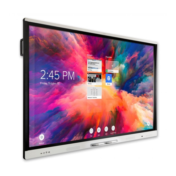
(see More information on page 16). About the display The SMART Board MX (V2) or MX (V2) Pro interactive display with iQ is the hub of your classroom. The display includes an extensive set of features and components: Touch You can do everything on the display that you can do at your computer—open and close applications,... -
Page 11: Iq Experience
Chapter 1 Welcome With Object Awareness™, the display responds automatically to the tool or object you’re using, whether it’s a pen, finger, or palm. The display’s Simultaneous Tool Differentiation technologies allow two people to write independently and simultaneously. iQ experience The display’s iQ experience provides one-touch access to collaborative tools, including a whiteboard, wireless screen sharing, and a web browser. -
Page 12: Room Computers And Guest Laptops
For more information, see Chapter 3: Connecting computers and other devices on page 30. Accessory slot You can install an OPS-compatible device, such as a SMART OPS PC module, in the accessory slot. The PCM8 series of SMART OPS PC modules provides a complete Windows 10 Pro installation. -
Page 13: Identifying Your Specific Model
You can use the remote control to turn the display on and off, adjust display settings, and so on. The IR sensor for the remote control is located in the bottom-right corner of the display’s frame. For more information about the remote control, see the SMART Board MX (V2) and MX (V2) Pro series interactive displays user guide (smarttech.com/kb/171554). -
Page 14: Accessories
SMART Open Pluggable Specification (OPS) PC modules provide a hassle-free Windows® 10 Pro installation based on eighth generation Intel® Core™ processors and are designed specifically to work with a SMART display. Available in two standard configurations, all OPS PC modules in the PCM8 series are WHQL certified and fully licensed with Windows 10 Pro. -
Page 15: Sba-100 Projection Audio System
Stands If you want to move the display from place to place, you can install it on a SMART mobile stand. If you are installing the display on a wall that cannot support the display’s full weight, you can install the display on a SMART floor stand. -
Page 16: More Information
More information In addition to this guide, SMART provides other documents for the display in the Support section of the SMART website (smarttech.com/support). Scan the QR code on the cover of this guide to view links to SMART Board MX (V2) and MX (V2) Pro series interactive display documents and other support resources. -
Page 17: Chapter 2: Installing The Display
Connecting to a network Connecting power and turning on the display for the first time SMART recommends that only trained installers install the display. This chapter is for installers. Installers should read this information along with the installation instructions included with the display before they install the display. -
Page 18: Using Transportation Aides
Chapter 2 Installing the display IMPORTANT Move the display at your own risk. SMART cannot accept liability for damages or injury that occur during the display’s transportation. When moving the display Follow local safety regulations and standards. Pack the display in its original packaging, including the pallet. -
Page 19: Installing The Display On A Wall
If the display’s glass is cracked or chipped, have it professionally inspected and repaired at a SMART authorized repair center. If the display’s glass shatters, carefully clean up the area and have the display repaired or replaced. -
Page 20: Choosing A Location
Chapter 2 Installing the display Choosing a location A display is typically installed at the room’s focal point, such as at the front of a classroom or meeting space. Selecting an appropriate location for the display is crucial for ensuring the best possible experience with the product. - Page 21 Installing the display Factor Considerations Visibility The display’s screen is clearly visible to all users in the room. SMART recommends users sit within a 178° viewing area: NOTE The viewing area depends on the display’s resolution and a variety of other factors.
-
Page 22: Choosing A Height
Be sure the wall you’re installing the display on can support the weight of the display and mounting equipment. If it can’t, consider using a SMART wall stand to transfer some of the weight from the wall to the floor (see smarttech.com/accessories). -
Page 23: Mounting The Display
Contact your authorized SMART reseller (smarttech.com/where) for information on SMART’s mounting options. If you choose a third-party option rather than one of SMART’s mounting options, be sure the wall mount can accommodate the display’s dimensions and support the display’s weight as well as the weight of any attached accessories. - Page 24 Chapter 2 Installing the display display’s weight and size. smarttech.com/kb/171555...
- Page 25 Chapter 2 Installing the display If you’re not using the included bolts to fasten the wall mount to the display, see the following table. SMART Board Minimum 14 mm + x mm MX255-V2 M8 length where x is the combined thickness of the wall mount...
-
Page 26: Installing The Display On A Stand
Using SMART mobile stands SMART mobile stands are designed for SMART interactive displays. They are height-adjustable. Some models include integrated speakers, a locking cabinet to secure equipment, and casters that swivel and lock for easy movement. -
Page 27: Connecting Power And Turning On The Display For The First Time
Chapter 2 Installing the display If you’re using one of the display’s RJ45 jacks to connect to a network, you can connect a computer to the other RJ45 jack to provide network access for the computer (pictured). This is particularly useful if there is only one wired network connection in the room. - Page 28 The display needs an internet connection for downloading and installing important updates. Ask the network administrator to confirm that the network has been correctly configured for the iQ experience. For more information about network configuration, see Connecting a SMART display with the iQ experience to a network.
- Page 29 Chapter 2 Installing the display 10. Select the apps you want to appear in the Apps Library, and then tap Next. To change which apps appear in the Apps Library, see Launcher on page 60. 11. Tap Finish. The Welcome screen appears. The display downloads and applies updates for the firmware and system software.
-
Page 30: Chapter 3: Connecting Computers And Other Devices
Viewing a connected computer’s input Setting a connected computer’s resolution and refresh rate Connecting USB drives, peripherals, and other devices Troubleshooting connected computers Connecting a SMART OPS PC module Viewing the OPS PC module input Connecting external displays Connecting other devices... -
Page 31: Installing Smart Software
Included with digital ink over applications, files, folders, SMART Learning Suite websites, and any other open window. You can purchase additional licenses or subscriptions to SMART software to install on other computers. The following software is also available but sold separately: Software Description... -
Page 32: Connecting Room Computers And Guest Laptops
You can then run the cables across floors or behind walls as needed. Side and bottom connector panel Front connector panel NOTES Install SMART software on any computers you connect to the display (see Installing SMART software on the previous page). smarttech.com/kb/171555... -
Page 33: Viewing A Connected Computer's Input
Chapter 3 Connecting computers and other devices Viewing a connected computer’s input To view a connected computer’s input 1. Connect the computer to the display. 2. Press the Input button on the front control panel or the remote control. The display shows thumbnails of the devices that are connected to the display’s inputs: NOTE A thumbnail with Touch enabled indicates a USB cable is connected between the display and... -
Page 34: Connecting Usb Drives, Peripherals, And Other Devices
Chapter 3 Connecting computers and other devices Resolution Input source aspect ratio Mode Refresh rate 1280 × 720 16:9 HD / 720p 59.94 Hz / 60 Hz 50 Hz 29.97 Hz / 30 Hz 25 Hz 23.98 Hz / 24 Hz 720 ×... -
Page 35: Connecting A Smart Ops Pc Module
Ensure the power switch on the back of the display beside the AC power inlet is in the OFF (O) position. You can install the SMART software that is included with the display on the OPS PC. For more information on installing software, see Installing SMART software on page 31. -
Page 36: Connecting Usb Drives, Peripherals, And Other Devices
The display includes the following USB Type A receptacles. You can connect USB drives, peripherals (such as keyboards), and other devices to these connectors and use the devices with the iQ experience, connected computers, and devices installed in the accessory slot (such as the SMART PCM8 series OPS PC). -
Page 37: Connecting An External Display
(SuperSpeed) (Hi-Speed) NOTE If a SMART OPS PC module is installed in the accessory slot, you can connect USB drives, peripherals, and other devices to the USB 2.0 Type-A, USB 3.0 Type-B, and USB Type-C receptacles on the OPS PC module to access those devices from the OPS PC module input. -
Page 38: Connecting An External Audio System
Chapter 3 Connecting computers and other devices If a SMART OPS PC module is installed in the accessory slot, you can connect an external display to the HDMI 1.4 out connector on the OPS PC module rather than the one on the display. This allows you to duplicate or extend the OPS PC module’s desktop to the external... -
Page 39: Connector Diagrams
Chapter 3 Connecting computers and other devices NOTE The S/PDIF audio is a fixed-volume output. Adjusting the display’s volume for its internal speakers does not affect the volume output of the S/PDIF port. Connecting room control systems A room control system enables users to control a room’s lighting, audio system and, possibly, the display. Some installations may require you to integrate the display with a room control system. - Page 40 Chapter 3 Connecting computers and other devices Connector Connects to Notes USB 2.0 Type-A [N/A] This connector is a service port. USB 3.0 Type-A Supported USB drives, See Connecting USB drives, peripherals, and other peripherals, and other devices on devices page 36 and USB cables and connectors.
-
Page 41: Front Connector Panel
Chapter 3 Connecting computers and other devices Front connector panel The following diagram and table present the connectors on the display’s front connector panel: Name Procedure USB 2.0 Type-A connector Connect USB drives and other devices that you want to use with the currently selected input source. USB 2.0 Type-A connector Connect a USB drive to update the display’s firmware. -
Page 42: Smart Pcm8 Series Ops Pc (Optional)
Chapter 3 Connecting computers and other devices SMART PCM8 series OPS PC (optional) The following diagram and table present the connectors on the optional SMART OPS PC module: Connector Connects to Notes USB Type-C Supported USB drives, See Connecting USB drives,... - Page 43 Chapter 3 Connecting computers and other devices Connector Connects to Notes Stereo 3.5 mm out External speakers or [N/A] headphones Stereo 3.5 mm in Microphone [N/A] smarttech.com/kb/171555...
-
Page 44: Chapter 4: Maintaining The Display
Turning off, turning on, and resetting the display In most situations, you can put the display into Sleep or Standby when not using it following the instructions in the SMART Board MX (V2) and MX (V2) Pro series interactive displays user guide (smarttech.com/kb/171554). -
Page 45: Cleaning And Maintaining Hardware
Chapter 4 Maintaining the display 2. Move the slider to the right. 3. Flick the switch beside the AC power inlet to the OFF (O) position. NOTE Wait at least 30 seconds before turning the display back on. To turn the display back on NOTE Touch is not available right after waking up the display or turning it on. -
Page 46: Cleaning The Screen
Chapter 4 Maintaining the display Cleaning the screen Follow these instructions to clean the screen without damaging its anti-glare coating or other product components. CAUTION Do not use permanent or dry-erase markers on the screen. If dry-erase markers are used on the screen, remove the ink as soon as possible with a lint-free, non-abrasive cloth. -
Page 47: Maintaining Ventilation
If condensation appears under the screen after you turn on the display, select an active video source and leave the display on for 48 hours. If the condensation doesn’t dissipate, contact SMART Support if the display is still under warranty. -
Page 48: Updating System Software
Chapter 4 Maintaining the display To remove the display safely, use two or more trained installers. WARNING Do not attempt to move the display by yourself. The display is very heavy. Do not move the display by connecting a rope or wire to the handles on the back. The display can fall and cause injury and product damage. -
Page 49: Applying An Automatic System Software Update Manually
Chapter 4 Maintaining the display When a system software update is available, the display downloads the update in the background then waits for four hours of inactivity. When that happens, the display shows a two-minute countdown before beginning the update. The countdown can be interrupted at any time. The update begins when the countdown finishes. -
Page 50: Chapter 5: Troubleshooting
Contacting your reseller for additional support This section explains how to resolve a variety of common issues with the display and SMART PCM8 OPS PC (if installed). If your specific symptoms aren’t covered below or the solutions to the symptoms don’t work, refer to the SMART knowledge base for additional troubleshooting information community.smarttech.com/s/topic/0TO0P000000Xt5yWAC/mx-series... -
Page 51: The Screen Is Blank Or There's A Problem With The Image On The Screen
Home screen. If it appears correctly, the issue is with the video input. Take a photograph of the screen and send it to SMART support. If SMART support determines that the issue is with the screen and the display is under warranty, you may be eligible for a replacement. - Page 52 Be aware that if two or more displays are mounted side-by-side, there could be minor differences in colors across the displays. This issue is not unique to SMART products. If the screen is completely lacking one color on the screen or the color problems occur on the Home screen, see Contacting your reseller for additional support on page 57.
-
Page 53: There's No Sound Or There's A Problem With The Sound
Chapter 5 Troubleshooting There’s no sound or there’s a problem with the sound Symptom Troubleshooting steps There’s no sound. If you’re using an external audio system, make sure it is turned on. Make sure the cables connecting the display to the computer are securely fastened. There is sound, but the volume is low. -
Page 54: Touch Isn't Working As Expected
For Mac computers with macOS Mojave, see How to resolve issues with installing and using SMART Learning Suite software on macOS Mojave. The display responds to touch Make sure jewelry or clothing doesn’t touch the board when erasing the ink. -
Page 55: The Pens And Erasers Aren't Working As Expected
When you write on the screen, the ink Make sure you are using a SMART Board MX (V2) interactive display pen. appears in the wrong place. Restart the display. See Turning off, turning on, and resetting the display on page 44. -
Page 56: Smart Software On Connected Computers Isn't Working As Expected
Wait two minutes. c. Press the power button to turn on the OPS PC module. If restarting the OPS PC module doesn’t resolve the issue, contact SMART support. There is an issue with Bluetooth. Fix Bluetooth problems in Windows 10: FAQ. -
Page 57: Contacting Your Reseller For Additional Support
(pictured). TIPS Scan the QR code on the label to view the SMART Board MX (V2) or MX (V2) Pro series interactive display support pages on the SMART website. -
Page 58: Appendix A: Adjusting Iq Settings
System-level settings apply to all users. See the settings for more information. Some settings aren’t available while you’re signed in to your SMART Account. Sign out of your SMART Account on the display to see all settings. - Page 59 Bluetooth Address Shows information about the display’s Turn on Bluetooth System Bluetooth. to view available Bluetooth devices. SMART Cloud [Status] Shows the status of SMART Cloud. [N/A] System SMART Cloud Status [N/A] Shows the service region. [N/A] System Service Region Personalization NOTE If iQ is disabled, Personalization settings are not available.
- Page 60 If iQ is disabled, Application settings are not available. Option Values Function Notes User or system setting Launcher Enables or disables SMART [N/A] User SMART Notebook Player Notebook Player in the Apps Library. Browser Enables or disables Browser in the [N/A] User Apps Library.
- Page 61 Devices that use AirPlay and Google Cast can’t connect to the display while a Miracast device is connected. SMART Support may ask users to Performance Logging System Performance Logging enable Performance Logging to is disabled by default. help diagnose issues.
- Page 62 Access to USB mass a USB drive. storage devices Enables or disables the iQ [N/A] System SMART Board with iQ experience. Inputs available on the display. Select the default input the The iQ System Default input display will use when starting.
- Page 63 Appendix A Adjusting iQ settings Option Values Function Notes User or system setting Power Disabled Sets the number of minutes of The default is 60 System Turn screen off after inactivity before the display minutes. 1 min goes to sleep. 5 mins 30 mins 1 hour...
- Page 64 Appendix A Adjusting iQ settings Option Values Function Notes User or system setting Enables or disables the [N/A] System Auto Brightness automatic brightness adjustment depending on the ambient light level. Advanced Display Options Very Cool Sets how colors appear on the [N/A] System Color...
- Page 65 Appendix A Adjusting iQ settings Option Values Function Notes User or system setting Enables or disables the When analog System Built-in Speakers display’s internal speakers. speakers are connected to the display, the display’s internal speakers are disabled automatically. Audio Properties 0–100 Sets the audio output from the Drag the slider all...
- Page 66 [N/A] Submit Log file to SMART. SMART Sends usage statistics and [N/A] User Improve the Experience error reports to SMART. [Support ID] Shows the support ID [N/A] [N/A] Support ID associated with the display. [Languages] Sets the language for the...
- Page 67 Appendix A Adjusting iQ settings Option Values Function Notes User or system setting Reveals characters when [N/A] System Make passwords visible typing a password in an app or website [N/A] Install certificates to connect [N/A] System Install certificates to a network. [N/A] View installed certificates.
- Page 68 Management on the display. Enabled Radix Viso version [N/A] Shows the Radix Viso version. [N/A] System About Help [N/A] Shows the SMART support [N/A] [N/A] site. [N/A] Select a name for your display. [N/A] System Board Name [N/A] Send feature request to...
- Page 69 Shows the display’s scaler [N/A] [N/A] Scaler version version. Legal Information [N/A] [N/A] [N/A] [N/A] End User License [N/A] Shows the SMART end user [N/A] [N/A] license agreement. Agreement [N/A] Shows the open source [N/A] [N/A] Open Source Licenses licenses. [N/A]...
-
Page 70: Appendix B: Managing The Display Using Rs-232
Appendix B Managing the display using RS-232 Configuring the serial interface settings Commands and responses Power state commands Input commands Brightness commands Freeze commands Screen shade commands Volume commands Mute commands Firmware version commands Model number commands Serial number commands Part number commands Asynchronous messages Resolving issues with managing the display using RS-232... -
Page 71: Configuring The Serial Interface Settings
SMART also offers SMART Remote Management cloud-based device-management software, which you can use to manage SMART Board interactive displays with iQ and devices running Windows, Chrome™ OS, Android™, and iOS operating systems. For more information, see SMART Remote Management. -
Page 72: Commands And Responses
Appendix B Managing the display using RS-232 When using a control system program instead of terminal program, all lines output from the display are preceded by a carriage return character (<CR>) and line feed character (<LF>) and then followed by a carriage return character (<CR>) and line feed character (<LF>), as shown in the example below. - Page 73 Appendix B Managing the display using RS-232 NOTES Use ASCII formatted commands. Commands aren’t case-sensitive and extra spacing is ignored. In many terminal applications on a computer, you can use the BACKSPACE key when typing commands. Review each entry carefully before sending a command to the display. Don’t send another command until you receive the response and the next command prompt (>).
-
Page 74: Power State Commands
Appendix B Managing the display using RS-232 To increase or decrease the value of a setting Use the set command to increase or decrease the value by a designated number. This example increases the volume by 5: >set volume+5 volume=70 >... -
Page 75: Input Commands
Appendix B Managing the display using RS-232 Power state Description READY The screen is off, but the display is ready to turn on when one of the following occurs: A user presses the Power button on the convenience panel or the remote control. -
Page 76: Brightness Commands
Appendix B Managing the display using RS-232 Brightness commands Get command Set command Response get brightness set brightness[Value] brightness=[Value] Where [Value] is one of the following: Where [Value] is a number between 5 and 100 +[Value] -[Value] =[5–100] Freeze commands Get command Set command Response... -
Page 77: Mute Commands
Appendix B Managing the display using RS-232 Mute commands Get command Set command Response get mute set mute[Value] mute=[Value] Where [Value] is one of the following: Where [Value] is one of the following: =off Firmware version commands Get command Response get fwversion fwversion=[Value] Where [Value] is the firmware version. -
Page 78: Part Number Commands
Appendix B Managing the display using RS-232 Part number commands Get command Response get partnum partnum=[Value] Where [Value] is the part number, including the revision. Asynchronous messages The display sends an asynchronous message when the front control panel, Settings app, or remote control are used to change a display’s setting that can be controlled by RS-232. -
Page 79: Resolving Issues With Managing The Display Using Rs-232
Appendix B Managing the display using RS-232 Change Asyncronous message Volume increase or decrease #volume=[Value] Where [Value] is a number between 0 and 100 Volume mute #mute=[Value] Where [Value] is one of the following: Resolving issues with managing the display using RS-232 The following table presents common issues with managing the display using RS-232 and explains how to resolve them:... -
Page 80: Appendix C: Enrolling The Display In Smart Remote Management
Enrolling the display in SMART Remote Management Your SMART Board MX (V2) or MX (V2) Pro has a built-in feature that enables you to enroll the display with your organization’s SMART Remote Management account. When you enroll one of these displays, you can... -
Page 81: Appendix D: Hardware Environmental Compliance
Appendix D Hardware environmental compliance SMART Technologies supports global efforts to ensure that electronic equipment is manufactured, sold and disposed of in a safe and environmentally friendly manner. Waste Electrical and Electronic Equipment and Battery regulations (WEEE and Battery Directives) Electrical and electronic equipment and batteries contain substances that can be harmful to the environment and to human health. - Page 82 SMART TECHNOLOGIES smarttech.com/support smarttech.com/contactsupport smarttech.com/kb/171555...
Need help?
Do you have a question about the MX V2 Pro Series and is the answer not in the manual?
Questions and answers