Table of Contents
Advertisement
Quick Links
Advertisement
Table of Contents

Subscribe to Our Youtube Channel
Related Manuals for Advantech PCIE-1753


Summary of Contents for Advantech PCIE-1753
- Page 1 User Manual PCIE-1753 96-Ch Digital I/O PCI Express Card...
- Page 2 No part of this manual may be reproduced, copied, translated, or transmitted in any form or by any means without the prior written permission of Advantech Co., Ltd. The information provided in this manual is intended to be accurate and reliable.
- Page 3 This product has passed the CE test for environmental specifications when shielded cables are used for external wiring. We recommend the use of shielded cables. This type of cable is available from Advantech. Please contact your local supplier for ordering information.
- Page 4 Document Feedback To assist us with improving this manual, we welcome all comments and constructive criticism. Please send all feedback in writing to support@advantech.com. Safety Precaution - Static Electricity Follow these simple precautions to protect yourself from harm and the products from damage.
- Page 5 In accordance with IEC 704-1:1982 specifications, the sound pressure level at the operator’s position should not exceed 70 dB (A). DISCLAIMER: These instructions are provided according to IEC 704-1 standards. Advantech disclaims all responsibility for the accuracy of any statements contained herein. PCIE-1753 User Manual...
- Page 6 Der arbeitsplatzbezogene Schalldruckpegel nach DIN 45 635 Teil 1000 beträgt 70dB(A) oder weiger. Haftungsausschluss: Die Bedienungsanleitungen wurden entsprechend der IEC- 704-1 erstellt. Advantech lehnt jegliche Verantwortung für die Richtigkeit der in die- sem Zusammenhang getätigten Aussagen ab. PCIE-1753 User Manual...
-
Page 7: Table Of Contents
20 3.3.2 Digital Output (TTL DO) .............. 21 Figure 3.6 Digital output signal connection....... 21 Appendix A Specifications ........23 Digital Input ..................... 24 Digital Output ..................24 General ....................24 Appendix B Block Diagram ........25 PCIE-1753 User Manual... - Page 8 PCIE-1753 User Manual viii...
-
Page 9: Chapter 1 Overview
Chapter Overview... -
Page 10: Introduction
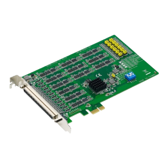
Introduction The PCIE-1753 is a 96-ch DI/O card with PCI Express bus. It provides 96 channels of parallel digital input/output compatible with 5V/TTL. It emulates mode 0 of the 8255 PPI chip, but the buffered circuits offer a higher driving capability than the 8255. -
Page 11: Applications
Parallel data transfer Sensing TTL, DTL, CMOS signal logic Driving indicator LEDs Installation Guide Before installing the PCIE-1753 card, please make sure you have the following nec- essary components: PCIE-1753 card PCIE-1753 Startup Manual Accessories (optional) ... - Page 12 CON0 is the female connector of the PCIE-1753 corresponding to the 100-pin SCSI male connector of the PCL-10268. CON1 and CON2 are also female connectors cor- responding to the two 68-pin SCSI male connectors of the PCL-10268. PCIE-1753 User Manual...
- Page 13 Chapter Installation...
-
Page 14: Chapter 2 Installation
This chapter gives users a package item checklist, proper instructions about unpack- ing, and step-by-step procedures for both the driver and card installation. Packing List After receiving your PCIE-1753 package, please first inspect its contents. The pack- age should contain the following items: PCIE-1753 card ... -
Page 15: Driver Installation
Driver Installation The driver package can be found on the Advantech Support Portal (https:// www.advantech.com/support). Search for PCIE-1753 on the support portal to locate the corresponding driver/SDK package for download. You’ll be able to install the Nav- igator after the download session finishes. -
Page 16: Software Utility
PCIE-1753 system. All these soft- ware packages are available on the Advantech website: http://www.advantech.com/. The Advantech Navigator is a utility that allows you to set up, configure, and test your device, and later stores your settings in a proprietary database. -
Page 17: Hardware Installation
Touch the metal part on the surface of your computer to neutralize the static electricity that might be on your body. Insert the PCIE-1753 card into a PCI Express slot. Hold the card only by its edges and carefully align it with the slot. Insert the card firmly into place. Use of excessive force must be avoided, otherwise the card might be damaged. - Page 18 After the PCIE-1753 card is installed, you can verify whether it is properly installed on your system through the Device Manager: Access the Device Manager through Control Panel/System/Device Manager. The device name of the PCIE-1753 should be listed on the Device Manager tab as follows.
-
Page 19: Chapter 3 Signal Connections
Chapter Signal Connections... -
Page 20: Overview
PC and other hardware devices. This chapter provides useful information about how to connect input and output signals to the PCIE-1753 via the I/O connector. Switch and Jumper Settings Figure 3.1 Jumper and switch settings Figure 3.2 Selected jumper and switch settings... -
Page 21: Keep Last Status (Jp1)
Jumper JP1 gives the PCIE-1753 a new and valuable function. With JP1 enabled, PCIE-1753 “memorizes” all I/O port settings and output values, and, in the event of a “hot” reset, the settings and output values present at the port just prior to reset are restored to each port following the reset. - Page 22 Set bits 4, 5, 6, 7 of port n as software-configurable input or output (default). Set bits 0, 1, 2, 3 of port n as output. Set bits 4, 5, 6, 7 of port n as output. PCIE-1753 User Manual...
-
Page 23: Board Id (Sw1)
Switch Position Board ID DOWN DOWN DOWN DOWN DOWN DOWN DOWN DOWN DOWN DOWN DOWN DOWN DOWN DOWN DOWN DOWN DOWN DOWN DOWN DOWN DOWN DOWN DOWN DOWN DOWN DOWN DOWN DOWN DOWN DOWN DOWN DOWN *Default setting. PCIE-1753 User Manual... -
Page 24: Pin Assignment Connections
Pin Assignment Connections PCIE-1753 User Manual... - Page 25 PCIE-1753 User Manual...
-
Page 26: Digital Input (Ttl Di, Pull-Up/-Down)
To prevent undetermined or fluctuating results when input is floating, the digi- tal input channel can be configured as internally pulled-up or pulled-down by software. This is shown in Figure 3.3. Figure 3.3 Digital input signal connection PCIE-1753 User Manual... - Page 27 DI terminal is sensed as shown in Figure 3.5. Be sure the voltage of the external source is within the allowable range of the ON state as specified in the device specifications. Figure 3.4 Digital input signal connection using a switch as internally pulled-up PCIE-1753 User Manual...
- Page 28 Figure 3.5 Digital input signal connection using a switch as internally pulled- down PCIE-1753 User Manual...
-
Page 29: Digital Output (Ttl Do)
Each digital output channel can source or sink only a finite amount of current. If this limit is exceeded, the output voltage will not stay in the specified voltage logic level. Refer to the device specifications for the maximum source and sink current values. PCIE-1753 User Manual... - Page 30 PCIE-1753 User Manual...
-
Page 31: Appendix A Specifications
Appendix Specifications... -
Page 32: Digital Input
330 mA typ. 400 mA max. Power Supply +5 V (±5%) 200 mA max. Output Form Factor PCI Express Dimensions 175 x 100 x 18 mm (6.9 x 3.9 x 0.7 in Weight 113 g I/O Connector 100-pin SCSI (ribbon type) PCIE-1753 User Manual... -
Page 33: Appendix B Block Diagram
Appendix Block Diagram... - Page 34 PCIE-1753 User Manual...
- Page 35 PCIE-1753 User Manual...
- Page 36 No part of this publication may be reproduced in any form or by any means, such as electronically, by photocopying, recording, or otherwise, without prior written permission from the publisher. All brand and product names are trademarks or registered trademarks of their respective companies. © Advantech Co., Ltd. 2023...
Need help?
Do you have a question about the PCIE-1753 and is the answer not in the manual?
Questions and answers