Table of Contents
Advertisement
Quick Links
Advertisement
Table of Contents

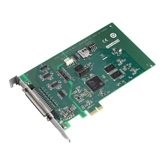
Summary of Contents for Advantech PCIE-1245
- Page 1 User Manual PCIE-1245/1245E 4-Axis Motion Control PCI Express Card...
- Page 2 No part of this manual may be reproduced, copied, translated, or transmitted in any form or by any means without the prior written permission of Advantech Co., Ltd. The information provided in this manual is intended to be accurate and reliable.
- Page 3 Product Warranty (2 years) Advantech warrants the original purchaser that each of its products will be free from defects in materials and workmanship for two years from the date of purchase. This warranty does not apply to any products that have been repaired or altered by persons other than repair personnel authorized by Advantech, or products that have been subject to misuse, abuse, accident, or improper installation.
- Page 4 Replace the battery only with the same or equivalent type as recommended by the manufacturer. Discard used batteries according to the manufacturer's instructions.” Note! Notes provide additional optional information. PCIE-1245/1245E User Manual...
-
Page 5: Table Of Contents
Driver Installation ..................8 Hardware Installation ................9 Chapter Signal Connections ......11 Overview ....................12 PCIE-1245 Switch and Jumper Settings ..........12 3.2.1 Board ID (SW1)................12 Table 3.1: BoardID Setting ............12 MTB-400 Terminal Board Pin Assignment..........13 3.3.1 Ground Screw for Case .............. - Page 6 PCIE-1245/1245E User Manual...
-
Page 7: Chapter 1 Introduction
Chapter Introduction This chapter introduces PCIE- 1245/1245E and lists their special features and detailed specifica- tions. -
Page 8: Features
Circular and helical interpolation (PCIE-1245 only) Hardware emergency input Position latch up to 10KHz and memory buffer 1K points (PCIE-1245 only) Position compare triggering up to 100 KHz, and memory buffer is up to 100 K ... -
Page 9: Specifications
Pulse Input Item Description Max frequency 5MHz x1, x2, x4 (A/B phase only) Type CW/CCW, PUL/DIR, AB x1, x2, x4 Output Electrical Characteristics EIA Standard RS-422 Protection All Isolation 1400V Min. width for Hi / Lo pulse 200ns PCIE-1245/1245E User Manual... -
Page 10: Digital Input
Protection IO Isolation 500V 1.3.8 High Speed Digital Output Item Description Channels CMP x2 Type NPN (sink type) 10Vdc Operation Voltage 28Vdc Max. sink current 250mA per channel (23°C) Max. output delay time Protection IO Isolation 500V PCIE-1245/1245E User Manual... -
Page 11: Software Function Comparison Table
Auto Blending Gantry Gantry Home Dynamic Compensation Look Ahead Path Velocity Following Tangential Application E-Gear Master/Slave Simultaneously Start/Stop Multi-Axis Latch Rising/Falling/Both Trigger Data/Auto/Table PCIE-1245/1245E User Manual... -
Page 12: Installation Guide
J4/J5, Yaskawa Sigma V/7, Panasonic A5/A6 and Delta A2) Industrial-grade PC with PCI Express bus slot Accessories Advantech offers a complete set of accessory products. These accessories include: Wiring Cables to Wiring Board PCL-30168M - PCL-30168M is a 68-pin shielded cable. To achieve a better sig- ... -
Page 13: Chapter 2 Installation
Chapter Installation This chapter instructs users how to proceed step-by-step process for driver and hardware installa- tion. -
Page 14: Unpacking
Driver Installation We recommend you to install the driver before you install the PCIE-1245/1245E card into your system. The DLL driver setup program for the card can be acquired from Advantech official website. -
Page 15: Hardware Installation
Save the screws to secure the retaining bracket of the interface card. Carefully grasp the upper edge of the PCIE-1245/1245E. Align the hole in the retaining bracket with the hole on the expansion slot and align the gold striped edge connector with the expansion slot socket. - Page 16 PCIE-1245/1245E User Manual...
-
Page 17: Chapter 3 Signal Connections
Chapter Signal Connections This chapter provides informa- tion about how to connect input and output signals. -
Page 18: Overview
Please refer to Table 3.1 for jumper and switch locations on PCIE-1245/1245E. 3.2.1 Board ID (SW1) PCIE-1245/1245E has a built-in DIP switch (SW1), which is used to define each card's unique identifier for Motion Utility. You can determine the BoardID identifier on the register as shown in Table 3.1. -
Page 19: Mtb-400 Terminal Board Pin Assignment
MTB-400 Terminal Board Pin Assignment 3.3.1 Ground Screw for Case 3.3.2 Power Input Name Description EGND Earth Ground -VEX +24V GND PCIE-1245/1245E User Manual... -
Page 20: Servo Drive Control
Servo In Position Servo Alarm Servo Alarm Reset Servo Error Counter Clear ECZ- Encoder Phase Z- ECB- Encoder Phase B- ECA- Encoder Phase A- SGND Signal Ground CCW-/DIR- Output Pulse CCW-/Direction- CW-/PULS- Output Pulse CW-/Pulse- No Connection PCIE-1245/1245E User Manual... -
Page 21: Digital Output
3.3.4 Digital Output Name Name OUT5 OUT0 OUT6 OUT1 OUT7 OUT2 OUT3 CMP0 OUT4 CMP1 PCIE-1245/1245E User Manual... - Page 22 Please note: Don’t connect FBV to +VEX of CN1. FBV does not support CM0 and CMP1. 3.3.4.2 OUT0-7 PCIE-1245/1245E provide extra 8-channel digital outputs. The recommended exter- nal wiring connection of DO for PCIE-1245/1245E are provided below: PCIE-1245/1245E User Manual...
-
Page 23: Home/Limit
CMP 0 & CMP 1 are specially designed for the users who can use the position trigger output to synchronize with other 3rd party vision devices. This function is supported by PCIE-1245 only. Please refer to 3.3.3.2 for wiring method. 3.3.5... -
Page 24: Digital Input
LTC1 3.3.6.1 IN0-7 PCIE-1245/1245E provide extra 8-channel digital inputs. The recommended external wiring connection of DI for PCIE-1245/1245E are pro- vided below: 3.3.6.2 LTC0/LTC1 (Latch) LTC 0 & LTC 1 are specially designed for the users who can use the position Latch output to acquire the current position value from command or feedback (Encoder) as the 2-wiring/3-wiring sensors active. - Page 25 PCIE-1245/1245E User Manual...
- Page 26 No part of this publication may be reproduced in any form or by any means, such as electronically, by photocopying, recording, or otherwise, without prior written permission from the publisher. All brand and product names are trademarks or registered trademarks of their respective companies. © Advantech Co., Ltd. 2022...


Need help?
Do you have a question about the PCIE-1245 and is the answer not in the manual?
Questions and answers