Sign In
Upload
Download
Table of Contents
Contents
Add to my manuals
Delete from my manuals
Share
URL of this page:
HTML Link:
Bookmark this page
Add
Manual will be automatically added to "My Manuals"
Print this page
×
Bookmark added
×
Added to my manuals
Manuals
Brands
UNI-T Manuals
Portable Generator
UTG1000X Series
User manual
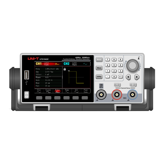
UNI-T UTG1000X Series User Manual
Function/arbitrary waveform generator
Hide thumbs
Also See for UTG1000X Series
:
Service manual
(21 pages)
,
Programming manual
(51 pages)
1
2
3
4
5
6
7
8
9
10
11
12
13
14
15
16
17
18
19
20
21
22
23
24
25
26
27
28
29
30
31
32
33
34
35
36
37
38
39
40
41
42
43
44
45
46
47
48
49
50
51
52
53
54
55
56
57
58
59
60
61
62
63
64
65
66
67
68
69
70
71
72
73
74
page
of
74
Go
/
74
Contents
Table of Contents
Troubleshooting
Bookmarks
Table of Contents
Copyright Information
Warranty
Chapter 1 User's Guide
Safety Requirements
Safety Precautions
Safety Statements
Safety Sign
Environmental Requirements
Connecting Power Supply
Electrostatic Protection
Preparation Work
Remote Control
Help Information
Main Features
Output Features
Function Interface
Chapter 2 Quick Start
Auxiliary Function
Channel Setting
Frequency Meter
Chinese Simplified
Chapter 4 Advanced Applications
Phase Modulation(Pm
Trigger Source
Chapter 5 Troubleshooting
Chapter 6 Service and Support
Appendix A Factory Setting
Appendix B Built-In Arbitrary Wave List
Advertisement
Quick Links
Download this manual
User's Manual
UTG1000X Series Function/Arbitrary Waveform Generator
Table of
Contents
Previous
Page
Next
Page
1
2
3
4
5
Advertisement
Table of Contents
Need help?
Do you have a question about the UTG1000X Series and is the answer not in the manual?
Ask a question
Questions and answers
Related Manuals for UNI-T UTG1000X Series
Test Equipment UNI-T UTG1000X Series Programming Manual
Function/arbitrary waveform generator (51 pages)
Portable Generator UNI-T UTG1000X Series Service Manual
Function/arbitrary waveform generator (21 pages)
Portable Generator UNI-T UTG1000 Series User Manual
Function/arbitrary waveform generator (91 pages)
Portable Generator UNI-T UTG1022X User Manual
Function/arbitrary waveform generator (74 pages)
Portable Generator UNI-T UTG1022X-PA User Manual
Function/arbitrary waveform generator (74 pages)
Portable Generator UNI-T UTG1010A User Manual
Function/arbitrary waveform generator (91 pages)
Portable Generator UNI-T UTG1005A User Manual
Function/arbitrary waveform generator (91 pages)
Portable Generator UNI-T UTG2122B User Manual
Function/arbitrary waveform generator (130 pages)
Portable Generator UNI-T UTG9000C-II Series User Manual
Function/arbitrary waveform generator (29 pages)
Portable Generator UNI-T UTG2025A Operating Manual
Function/arbitrary waveform generator (124 pages)
Portable Generator UNI-T UTG9504T User Manual
Function/ arbitrary waveform generator (157 pages)
Portable Generator UNI-T UTG9000T Series Quick Manual
Function/arbitary waveform generator (21 pages)
Portable Generator UNI-T UTG900E Series User Manual
Function generator (44 pages)
Portable Generator UNI-T UTG900E Series Programming Manual
Function/arbitrary waveform generator (41 pages)
Portable Generator UNI-T UTG900E Series User Manual
Function generator (44 pages)
Portable Generator UNI-T UTG4000A Series Programming Manual
Function/arbitrary waveform generator (53 pages)
This manual is also suitable for:
Utg1042x
Utg1022x
Utg1022x-pa
Table of Contents
Print
Rename the bookmark
Delete bookmark?
Delete from my manuals?
Login
Sign In
OR
Sign in with Facebook
Sign in with Google
Upload manual
Upload from disk
Upload from URL


Need help?
Do you have a question about the UTG1000X Series and is the answer not in the manual?
Questions and answers