
Related Manuals for UNI-T UTG1000X Series


Summary of Contents for UNI-T UTG1000X Series
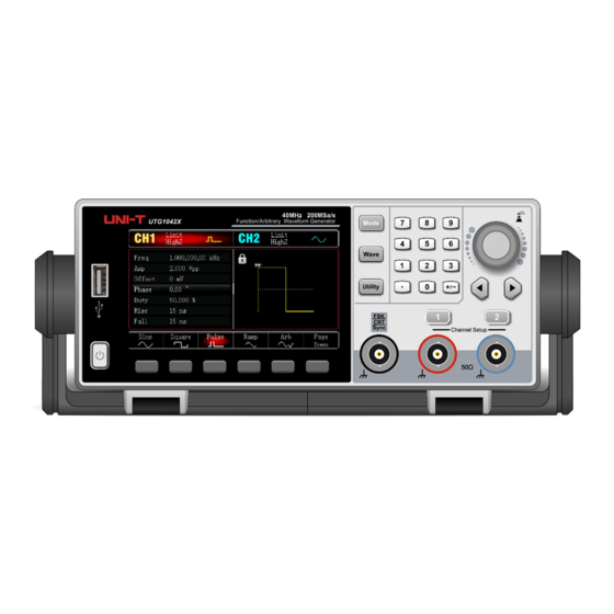
- Page 1 Service Manual UTG1000X Series Service Manual UTG1000X Series Function/Arbitrary Waveform Generator Instruments.uni-trend.com 1 / 20...
-
Page 2: Copyright Information
UNI-T, and prepay the freight and provide a copy of the original purchaser’s proof of purchase. If the product is to be shipped to a location within the country where the UNI-T repair center is located, UNI- T shall pay for the return of the product to the customer. -
Page 3: Safety Information
Service Manual UTG1000X Series 1. Overview Safety Information This section contains information and warnings that must be observed to keep the instrument operating under appropriate safety conditions. In addition to the safety precautions indicated in this section, you must follow generally accepted safety procedures. -
Page 4: Safety Signs
Service Manual UTG1000X Series Safety Signs Danger Indicates a warning of a possible electric shock hazard that could result in personal injury or death. Warning Indicates a point requiring caution, which may result in personal injury or damage to the instrument. -
Page 5: Safety Requirements
Service Manual UTG1000X Series Three-phase public power supply equipment and outdoor power supply line equipment. Equipment designed for "primary connection", CAT IV such as the power distribution system of the power station; power meters, front-end over-set protection, and any outdoor transmission lines. - Page 6 Service Manual UTG1000X Series Static electricity will cause damage to the instrument, and the test should be performed in an anti-static area as much as possible. Before connecting the cable to Anti-static the instrument, briefly ground its inner and outer conductors to discharge static protection-on electricity.
-
Page 7: Environmental Requirements
Service Manual UTG1000X Series Maintain Poor ventilation can cause the temperature of the instrument to rise, which can cause proper damage to the the instrument. ventilation Keep well-ventilated when in use, and check the vents and fans regularly. Please keep it... -
Page 8: Static Protection
● Check serial numbers and system information UNI-T is constantly improving its product performance, usability, and reliability. UNI-T service personnel can access the according to the instrument serial number and system information. The serial number is located on the rear cover serial label, or the analyzer is powered on, press Utility→... -
Page 9: Structure Introduction
Service Manual UTG1000X Series 3.Structure introduction Front panel components As shown below: Parts List Serial number Parts name Serial number Parts name Switch power switch Keypad Plug-in Components lens Motherboard plug-in components Front frame Floor mat 4.3 inches true color LCD screen... - Page 10 Service Manual UTG1000X Series Parts List: Serial number Parts name Serial number Parts name Power amplifier module plug-in Back frame components Back cover 1.0mm galvanized Floor mat sheet AC two-in-one card power Power Board Plug-In Components socket three plugs with safety...
-
Page 11: Maintenance
Service Manual UTG1000X Series 4.Maintenance This section contains information needed to perform periodic and corrective maintenance on the instrument. Pre-discharge electrostatic discharge Before servicing this product read the General Safety Summary and Service Safety Summary at the front of the manual, as well as the following ESD information. -
Page 12: Display Cleaning
Service Manual UTG1000X Series Check - Appearance. Inspect the exterior of the instrument for damage, wear, and missing parts. Immediately repair defects that could result in personal injury or further use of the instrument. External Checklist Item Examination Repair operation... - Page 13 Service Manual UTG1000X Series 5.Disassemble Removal tool Use the following tools to remove or replace modules in the function/arbitrary waveform generator. Item Tools Description Torque screwdriver Model see disassembly steps Upholstered Prevents damage to the screen and knobs when removing the...
-
Page 14: Removing The Front Panel Assembly
Service Manual UTG1000X Series 2. Gently remove the front panel, as shown in the figure below. Note: When the front panel is placed downward, it is necessary to avoid the knob cap to avoid damage to the knob. Removing the Front Panel Assembly The following procedure describes the removal of the front panel. - Page 15 Service Manual UTG1000X Series 4、 Remove the fan, and use a T10 Torque screwdriver to remove the four screws and the power supply cable of the fan. As shown below: 5、 Remove the motherboard; use a T10 Torque screwdriver to remove the 5 screws on the front panel and the display cable.
-
Page 16: Removing The Rear Panel Assembly
Service Manual UTG1000X Series 7、 Remove the keyboard; use a T10 Torque screwdriver to remove the two switch key screws, and then remove the 8 fixing screws of the keyboard to remove the keyboard and the screen. Note: Before removing the keyboard, the knob on the front panel needs to be removed. - Page 17 Service Manual UTG1000X Series Remove the power module; use a T10 Torque screwdriver to remove the 5 screws and the blue wire, as shown in the figure below: 4、 Remove the rear panel; use a T10 Torque screwdriver to remove the 6 screws and the grounding wire, as shown in the figure below: 5、...
-
Page 18: Service Level
Service Manual UTG1000X Series Service level This section contains information and procedures to help you determine if a power failure is an instrument problem. If the power fails, the instrument needs to be sent back to the Uni-Tech service center for repair, because other internal electronic components or modules cannot be replaced by the user. -
Page 19: After Maintenance
Uni-Tech Service Center for adjustment. 6.Appendix Warranty Summary UNI-T (Union Technology (China) Co., Ltd.) guarantees that the products it produces and sells will be free from any defects in materials and workmanship within one year from the date of shipment from authorized Instruments.uni-trend.com... - Page 20 If the product proves to be defective during the warranty period, UNI-T will repair and replace it according to the detailed provisions of the warranty. To arrange repairs or to obtain a full copy of the warranty, please contact your nearest UNI-T sales and repair office.
Need help?
Do you have a question about the UTG1000X Series and is the answer not in the manual?
Questions and answers