Table of Contents
Advertisement
Quick Links
Advertisement
Table of Contents

Related Manuals for HTP Revolution 2500


Summary of Contents for HTP Revolution 2500
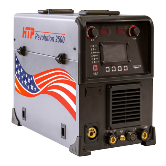
- Page 1 Revolution™ 2500...
-
Page 2: Warranty
Thirty (30) Days after discovery. HTP America, Inc. has reserved the right to make changes in design or add any improvements to its products, at any time, without incurring any obligation to install the same on equipment. -
Page 3: Safety Suggestions
This warranty is void unless the warranty card is sent to HTP America, Inc. within Fifteen (15) Business Days from the date of purchase. EXCLUSIONS TO WARRANTY: 1) MIG guns and TIG welding torches are warranted for a period of Ninety (90) Days against defects in material and workmanship. -
Page 4: Electric Shock Can Kill
- If you develop eye, nose, or throat irritation during welding, stop welding immediately. This is an indication that ventilation is not adequate. Do not continue to weld until ventilation is improved. ELECTRIC SHOCK CAN KILL. Exposed, electrically hot conductors, other bare metal in the welding circuit, or ungrounded, electrically hot equipment can fatally shock a person whose body becomes a conductor. -
Page 6: Specifications
4) SPECIFICATIONS Revolution 2500 Specifications Single Phase : 115 – 240 V Input Voltage ( volts ) Electronic Overload Protection STICK ( and Pulse Stick ) Welding Modes TIG ( and Pulse Tig ) MIG MANUAL MIG 2T ( and Pulse Mig ) -
Page 7: Data Plate
DATA PLATE... -
Page 8: Front Panel Connections
FRONT PANEL CONNECTIONS Fig. 1 Z – central connector for MIG gun U – connector for tig torch or electrode holder N – gas for tig torch (outlet) Y – remote control receptacle W – WORK (ground) clamp, automatic polarity reversal depending on welding process USB PORT . -
Page 9: Back Panel Connections
BACK PANEL CONNECTIONS Fig. 3 P – power switch Q – connector for tig torch or electrode holder R – port for TIG and Spool Gun shielding gas S – port for MIG shielding gas T – data plate... -
Page 10: Electrical Connections
When operating this machine on 110/120volt please use a dedicated circuit (no other lights or grinders or any other appliances shall share the circuit with the welding machine). The REVOLUTION 2500 can be operated on a 15amp 110/120volt circuit but with even more limitations in regard on maximum output and duty cycle, for best results welding on 110/120 volt a dedicated 20amp circuit is recommended. -
Page 11: Front Panel Controls
FRONT PANEL CONTROLS Fig. 4 STICK WELDING LED ; TIG WELDING LED ; MIG MANUAL WELDING LED; MIG SYNERGIC 2T LED ; MIG SYNERGIC 4T LED ; MIG SYNERGIC 4TS LED - SELECT MODE button - Allows you to access different welding modes by pressing repeatedly. - Page 12 AC Balance Balance refers to the time the arc spends above or, in the case of HTP machines, below the zero line. What does that mean? Imagine you weld AC and you set your frequency not to 100Hz but to 1Hz (1Hz used for the purpose of easy demonstration;...
- Page 13 The strongest effects and the best results occur when you set the difference between the peak amperage and the background amperage rather high. With the Revolution 2500, you can adjust the pulse frequency from 0.4 to 1000 PPS, the background amps from 10 to 90%, and the peak time...
- Page 14 Pulse in Stick Advantages of Pulse Welding Pulse welding includes ALL of the following advantages, but not all at the same time. At a later point in the manual, we cover, in more detail, suggested settings regarding how, when, and where certain situations apply.
- Page 15 Lift start, not to be mistaken for scratch-start, can be used to ignite a DC or an AC welding arc with the Revolution 2500. If you use a foot pedal, turn HF off in the menu, and then touch the clean and cold tungsten electrode to the clean material you plan to weld on.
- Page 16 HOW TO WELD – STEP BY STEP MANUAL / EASY SET Electrode welding has two types of settings. MANUAL and EASY SET. STICK ( SMAW ) MANUAL. In Manual mode it works as with a normal electrode inverter welder by setting the welding current, Arc Force and Hot Start.
- Page 17 6) Select the Manual or Easy set function 12) Select the size of the electrode through the through the button ( Fig.4,ref.9 ) or the button ( Fig.4 ,ref. 11 ) or the encoder encoder ( Fig.4,ref. 12 ) ( Fig.4,ref.12 ) ; 7) To activate the selected function, press the 13) To confirm the choice, press the button button...
- Page 18 PULSE PARAMETERS ADJUSTMENT ( Only in MANUAL MODE ) 23) To change the Background amps value, move the encoder ( Fig.4,ref.12 ) 17) Press PUL SET button (Fig. 4, ref.10); 18) Pulse Frequency Adjustment (PPS) In EASY MODE the pulse parameters are not adjustable .
-
Page 19: Tig Welding
TIG WELDING TIG 2T Use the Select Mode button ( Fig.4,ref 7 ) to toggle through the menu until the LED next to 2T illuminates. You are now in the TIG 2T welding mode. SQUARE is the AC Wave Form. SQUARE WAVE : The standard wave form modern inverter... - Page 20 AC Frequency; 4) Then you will go to a new screen ( Only if Amps; you select DC mode ) AC Balance For regulate the parameters AC FREQUENCY and AC BALANCE press the button AC SET ( Fig.4, ref.10 ). With the encoder ( Fig.4, ref.
- Page 21 Here, you can select your pre-gas flow in Fig.4,ref.9 ) , to move to the final station of seconds. by turning encoder ( Fig.4,ref. 12 ) the sequencer—post-gas flow . until you reach your desired pre-gas flow duration. In order to adjust the next value of the sequencer, in this case t1 (slope up), press button ( Fig.4,ref.9 );...
- Page 22 Your starting current does not always have to The Revolution 2500 allows you to adjust be 4 amps! When working with thicker, TIG Hot start in both AC and DC. Most other...
-
Page 23: Remote Control
Press the button ( Fig.4,ref. 11 ) to go to DC PULSE MODE Background amps regulation .Background When you select The Pulse mode DC you can amp regulation is a percentage of the welding regulate three different parameters . current . For regulate the pulse parameters press the Press the button ( HOME ) ( Fig.4,ref. - Page 24 Select REMOTE with the button MIG MANUAL MODE ( Fig.4,ref.9 ) Use the SELECT MODE button ( Fig.4,ref. 7 ) to toggle through the menu until the LED next to MIG MANUAL illuminates. You are now in the MIG MANUAL welding mode. Press the button CHANGE ( Fig.4,ref.11 ) and then the button ( HOME ) ( Fig.4...
- Page 25 Select the GAS though the button SYNERGIC / PULSED / DOUBLE PULSED MIG ( Fig.4,ref.9) or the encoder ( Fig.4,ref. 12) To activate the selected function, press the Press the button ( Fig.4,ref. 8 ) button ( Fig.4,ref. 11 ) Select the Synergic Mig , Pulsed Mig or Double Pulsed Mig function through the button...
- Page 26 By pressing the button E ( Fig.4,ref. 9 ) once, encoder ( Fig.4,ref. 12 ). After you release the you enter the setup menu (Fig. 24). trigger, the machine still runs for the amount of time selected, but tapers down automatically during the slope down time.
- Page 27 The Post gas flow is adjustable from 0,1 to 15 the wire. Depending on the setting, there sec. might not be a ball on the end of the wire that needs to be clipped off before re-striking an Pressing the button ] ( Fig.4,ref.11 ) there arc.
- Page 28 It is possible adjust the t2 value from 0,1 to 10 seconds. Pressing again the button it is possible regulate the Slope Down Time t3. It works like in MIG 2T. Pressing again the button it is possible regulate the “Hot Start”. It is possible adjust the t2 value from 0,1 to 10 seconds.
- Page 29 Pressing again the button it is possible REMOTE CONTROL regulate the Post Gas Flow time. To select e activate the Remote Control press the button to go into the settings menu. With the button select Remote . Press the button CHANGE ( Fig.4,ref.11 ) and select AUTO It works like in MIG 2T/4T.
-
Page 30: Factory Reset
Pro Tip: when turing on the spool gun also With the button select MIG-Manual pol . turn on remote as the HTP spoolgun has Press the button CHANGE ( Fig.4,ref.11 ) remote control functions build in. and next to MIG-Manual pol . it is possible see STD ( standard ) or REV ( reverse ). - Page 32 WIRING DIAGRAM – Revolution 2500...
-
Page 33: Exploded View
EXPLODED VIEW... - Page 34 PART LIST – REVOLUTION 2500 Position Part # Description 6610620000 Knob 6616970010 Instrument Label 6614220000 Display Protection 6646200000 Central Connector Frame 6427400000 Welding Socket 63197000 + 6318500 Gas outlet TIG torch 614621000L Remote Control Receptacle 14 pin 64274000000 Welding Socket...
- Page 35 Position Part # Description 6610930L00 Rear Fan Cover 621003CG00 Cover 6472400000 Switch 614322000L Fan 120 x 120 x 38 614614000L Primary Inverter Pcb Group 6610340000 Handle 614589000L Power Transformer 6647000000 Spool Holder 6210050K00 Protection Pcb 614509000L USB Pcb 611902000L Encoder 6613850L10 Plastic Frame 614116000L...
- Page 36 EXPLODED VIEW WIRE FEEDER N° DESCRIPTION CODE 2- R Housing SF 15030, front composite 613704000L 2- R Housing SF 15030-37, back composite 613705000L Gear to motor 6613110000 Intermediary gear 6613120000 Gear with main axle 6362100000 Pressure arm ø 30mm composite, left 6363500000 Pressure adjustment unit, black 6363600000...
Need help?
Do you have a question about the Revolution 2500 and is the answer not in the manual?
Questions and answers