
Related Manuals for HTP Invertig 201 AC/DC


Summary of Contents for HTP Invertig 201 AC/DC
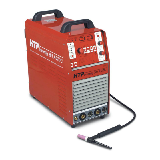
- Page 1 America Inc. Invertig 201 AC/DC Owner’s Manual HTP America, Inc. 3200 Nordic Road Arlington Heights, IL 60005-4729 • • 1-800-USA-WELD 847-357-0700 FAX: 847-357-0744 www.usaweld.com • • •...
- Page 2 HTP America, Inc. will repair and replace, at its factory, any part or parts thereof, products to be returned to HTP America, Inc. with transportation charges prepaid and which its examination shall disclose to its satisfaction to have been thus defective.
-
Page 3: Safety Suggestions
For more information, refer to the following standards and Safety Suggestions comply as applicable. Electric arc welding produces ultra-violet rays, which are harmful to skin and eyes. Ultra-violet radiation can penetrate 1. ANSI Standard Z49.1 SAFETY IN WELDING AND lightweight clothing, reflect from light colored surfaces, and CUTTING, obtainable from the American Welding Society, burn the skin and eyes. -
Page 4: Electrical Connection
Welding Current Indicator Lamp will be in the “APMS” display. Those displays will be covered in the illuminated. section covering those touch pad buttons. If your Invertig 201 AC/DC is in the stick-welding mode, the welding current indicator lamp will be illuminated all the time. - Page 5 The welding mode push button allows you to selects the welding current of 75 amps. Depress and release the trigger again mode of your Invertig 201 AC/DC. and you will go back to 150 amps. To stop welding, depress the trigger for 5 seconds or longer. When the trigger is A) Stick Welding –...
- Page 6 When the welding mode is in the TIG SPOT Mode this button To adjust the pulse duty cycle, depress and release the “PULSE adjusts the spot welding time from 0.1 sec to 10.0 sec in 0.1 sec ON” button until “dut” which is displayed in the “VOLTS” increments.
- Page 7 It is also possible to adjust the starting amperage. When you push the remote on button, “rem” is flashing and displayed in the “Volts” display (#4) and the starting amperage is flashing and displayed in the “Amps” display (#5). While both displays are flashing, adjust the amperage adjustment knob (#8) to adjust the starting amperage.
-
Page 8: Front Panel Connections
When TIG welding, this is where the ground cable connects to the front of the TIG Adapter. That’s right, we said the ground Use a flowmeter as HTP Part #12020-F which is compatible cable. This is called straight polarity, with the torch negative with Argon cylinders and has a barbed fitting for the delivery and the work positive. - Page 9 2% thoriated tungsten. It offers good arc starting characteristics and longer life than The HTP Tungsten Sharpener is an excellent tool for precisely 2% thoriated. Can be used for both AC and DC welding with sharpening tungsten electrodes without any fear of contanimation.
- Page 10 General Welding Parameters Quick Set Up Following are some “rule of thumb” welding parameters 1) Welding Mode in 2T for foot pedal. tungsten diameters and amperage settings for welding different 2) Steel welding AC off – Aluminum Welding AC on thicknesses of aluminum and steel.
- Page 11 6) Generally speaking, use a 1/16" diameter filler rod for applications where the material is 1/8" and less. Use a 3/32" diameter rod for 1/8" and thicker. The following Filler Rod is available from HTP in 1 lb. tubes which are tightly sealed to prevent oxidation.
- Page 12 17 Series Air-Cooled Tig Torch Parts Breakdown Tungsten Diameter Illus # Description 0.040" 1/16" 3/32" 1/8" Standard Configuration Alumina Nozzle 10N49 10N48 10N47 10N46 Collet Body 10N30 10N31 10N32 10N28 Collet 10N22 10N23 10N24 10N25 Gas Lens Configuration (optional) Alumina Nozzle 54N17 54N16 54N15...
- Page 13 20 Series Water Cooled Tig Torch Parts Breakdown Tungsten Diameter Illus # Description 0.040" 1/16" 3/32" 1/8" Gas Lens Configuration (optional) Alumina Nozzle 53N59 53N60 53N61 53N61S Gas Lens Collet Body 45V42 45V43 45V44 45V45 Collet 13N21 13N22 13N23 13N24 Standard Configuration Alumina Nozzle 13N08...
- Page 14 Duty Cycle Curve HTP Invertig 201 Duty Cycle Curve - HTP Invertig 201 Current (A) Voltage/Amp Curve HTP Invertig 201 Volt/Amp Curve - HTP Invertig 201 Series Amps...
- Page 15 Note the threads are left hand. Tighten down to 10 Deg F. It is also recommended to use HTP’s using 2 wrenches. Since the seal is made by the fitting and Eliminator which will prevent algae from growing in your cooling system.
- Page 16 HTP Invertig 201 Parts Breakdown...
- Page 17 HTP Invertig 201 Spare Parts List Illus # Part # Description 66109 HANDLE 62500 62483 INTERMEDIATE PANEL 62349 SIDE PANEL 610092 FRONT PANEL ASSEMBLY 613330 DRIVER PCB 610716 LOGIC PCB 62482 FRONT PANEL 660136 FRONT PLATE 66208 KNOB d.29 66121 KNOB d.22...
- Page 18 Pyrex Cup Kits Nothing makes welding easier than being able to see what you are doing. HTP’s Pyrex Cup kits do just that! The clear Pyrex cup gives you unparalleled visibility of the arc and work. The Pyrex Cup kit also comes standard with our special gas saver gas lens kit.
- Page 19 Pyrex Cup Parts Tungsten Diameter Illus # Description 0.040" 1/16" 3/32" 1/8" For 9 and 20 Tig Torches Pyrex Cup PYR8S PYR8S PYR8S PYR8S Tungsten Adapter PYR040TA PYR116TA PYR332TA PYR18TA Collet Body PYR20CB PYR20CB PYR20CB PYR20CB Wedge Collet PYR20C040 PYR20C116 PYR20C332 PYR20C18 Heat Shield...
- Page 20 Need to change the angle of your Tig torch to get into that tight area? Trouble is, with a standard Tig torch you can’t. Well, HTP has the answer: our Flex Neck Tig Torch. This unique torch lets you bend the end of your Tig torch into virtually any position, allowing you quick, easy access to practically any tight, cramped or out-of-the-way spot.
- Page 21 HTP Invertig 201 - Wiring Diagram...
- Page 22 HTP Invertig 201 AC/DC Troubleshooting Guide Have a visual check inside the machine: Replace PCB with do you find burst, burnt or blown up damaged parts? components Are wirings damaged? Which of following problems do Switch machine on you have?
- Page 23 Is the problem on plug or on board? Do you have a voltage Do you have a voltage Do you have a voltage of 230/240Vac at input of 230/240Vac on of 230/240Vac on input of switch S1 ? input of power cable? of PCB 4? Replace Replace switch...
- Page 24 Is fuse F1 Go to intact? point C Replace fuse F1 Replace transformer T AUX1 Do you have 3 secondary voltages on aux. Do you have voltage of transformer T AUX1 230/240Vac on input of (0-9V/0-18V/0-24V)? transformer T AUX1? Go to point I Replace front panel group...
Need help?
Do you have a question about the Invertig 201 AC/DC and is the answer not in the manual?
Questions and answers