
Related Manuals for HTP Invertig 251 AC/DC


Summary of Contents for HTP Invertig 251 AC/DC
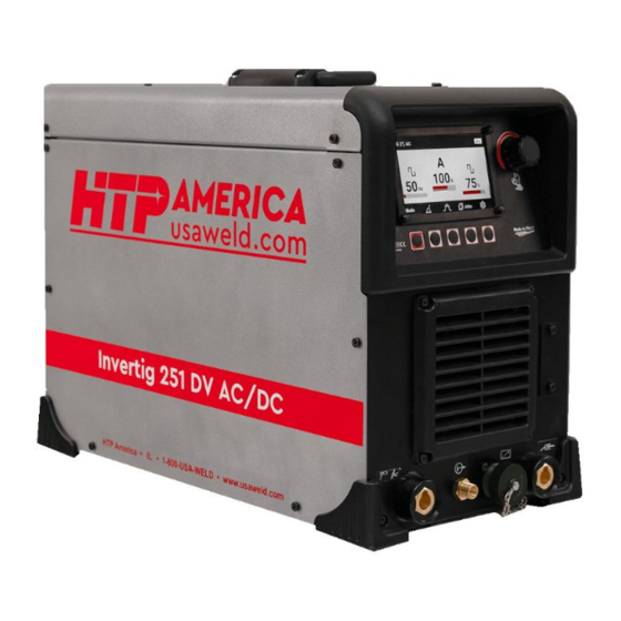
- Page 1 Invertig™ 251 AC/DC Invertig™ 251 DV AC/DC 180 Joey Drive Elk Grove Village, IL 60007-1304 Ph: (847) 357-0700 Fax: (847) 357-0744 Email: customerservice@htpweld.com Web: www.usaweld.com...
-
Page 3: Other Functions
INDEX 1) FOREWORD 2) WARRANTY 3) SAFETY SUGGESTIONS 4) SPECIFICATIONS 5) ELECTRICAL CONNECTION 6) FRONT PANEL CONNECTIONS 7) REAR PANEL CONNECTIONS 8) FRONT PANEL CONTROLS 9) EXPLANATIONS 12-15 a) Wave Forms b) AC Balance c) AC Frequency d) Asymmetric AC e) Pulse in DC TIG 13-14 f) Double Pulse in DC TIG g) Tig DC Dynamin Power h) Pulse in Stick i) Hot Start l) High Frequency & Lift Start m) Lift Pipe Smart 10) HOW TO WELD—STEP BY STEP a) STICK... -
Page 4: Warranty
Thirty (30) Days after discovery. HTP America, Inc. has reserved the right to make changes in design or add any improvements to its products, at any time, without incurring any obligation to install the same on current or previously sold equipment. -
Page 5: Safety Suggestions
Note: This warranty is to the original purchaser only. The warranty can be transferred to another owner, with HTP’s approval, for a warranty transfer fee. HTP America, Inc. must be notified within Fourteen (14) Days of the sale and must be provided with the contact information of the original owner, the contact information of the new owner, and the serial number of the machine. - Page 6 - Ensure that the panels covering the welding machine are firmly secured in place when the machine is connected to the power supply. - Insulate yourself from the workbench and from the floor (ground); use insulating footwear and gloves. - Keep gloves, footwear, clothes, the work area, and the welding equipment clean and dry. - Check the machine power cable frequently;...
-
Page 8: Specifications
4) SPECIFICATIONS Invertig 251 AC/DC – Invertig 251 AC/DC DV Specifications Input Voltage (volts) Single Phase: 120 – 240 V Electronic Overload Protection Welding Modes STICK (and Pulse Stick) TIG 2T ( pedal/slider ) (and Pulse TIG) TIG 2T TIG 4T... - Page 9 DATA PLATE INVERTIG 251 DV AC/DC *tested at ambient temperature of 104°F*...
- Page 10 DATA PLATE INVERTIG 251 AC/DC *tested at ambient temperature of 104°F*...
-
Page 11: Electrical Connections
10AWG and should not exceed a length of 100’ regardless if you operate the machine on 110/120 or 220/240 volts. To operate the machine on 110/120 volt please use adapter plug (HTP part number 515P650R18) to adapt to 110/120 volt. To operate the machine on 110/120 volts simply plug machine into the wall outlet, wait for the PF0 message to clear and the machine is ready to be used. -
Page 12: Front Panel Connections
6) FRONT PANEL CONNECTIONS Fig. 1 U – Connector for TIG torch or electrode holder N – Gas for TIG torch (outlet) Y – Remote control receptacle W – WORK (ground) clamp, automatic polarity reversal depending on welding process USB PORT. This USB port is used only for software updates. -
Page 13: Rear Panel Connections
7) REAR PANEL CONNECTIONS P – On/Off switch Fig. 3 Q – Power plug R – Gas hose connection S – Data plate/Serial Number T – AWC (water cooler) Connection... -
Page 14: Front Panel Controls
8) FRONT PANEL CONTROLS Fig. 4 MODE / HOME BUTTON PROCESS SELECTION BUTTON MAIN WELDING SETTINGS BUTTON JOBS BUTTON MACHINE SETUP BUTTON ENCODER (turn to select and push to confirm selection) MAIN DISPLAY – All welding parameters LIVE MACHINE LED... - Page 15 AC Balance Balance refers to the time the arc spends above or, in the case of HTP machines, below the zero line. What does that mean? Imagine you weld AC and you set your frequency not to 100Hz but to 1Hz (1Hz used for the purpose of easy demonstration;...
- Page 16 c) AC Frequency AC frequency does mainly two things. First, AC frequency focuses the arc. Higher frequencies feature a more focused arc and a narrower frost line, which works really well on thin material. On thick material, higher frequencies tend to make it hard to join two pieces of material, as the focused arc wants to cling to only one piece.
- Page 17 and you set the background amperage and the peak time (pulse-on time or duty) based on that maximum amperage. You set both the background amperage and the peak time as a percentage of the maximum amperage. Peak time refers to the peak pulse current number. The actual duration of the peak time, in seconds or in fractions of a second, depends on the third variable—the pulse frequency.
- Page 18 f) Double Pulse in DC TIG Double pulse TIG combines two types of pulsation. A slow and a fast pulse The advantages of Double pulse are: Higher welding speed Deeper penetration Increased arc focus Better control of heat input The most suitable applications for double pulse TIG are: Thin materials Corner joints Stainless steel...
- Page 19 i) Hot Start Hot-Start for Stick Hot-start when stick welding gives a short burst of current to ignite hard to start electrodes. Hot-Start for TIG The hot-start for TIG function is available in AC and in DC. Hot-start provides a short (in the range of milliseconds) burst of current to ignite the arc.
- Page 20 10) HOW TO WELD MANUAL / EASY SET Electrode welding has two types of settings. – STEP BY STEP MANUAL and EASY SET. a) STICK (SMAW) MANUAL- In Manual mode it works as with 1) Press the button MODE (Fig. 4, ref.1, Pg a normal electrode inverter welder by setting 11) to enter in the menu.
- Page 21 4a) With the encoder (Fig. 4, ref.6, Pg 11) it STICK SETTINGS is possible to select the functions and press 1) To enter in the Stick Settings adjustment the encoder to confirm the choice. menu, press the button (Fig.4,ref. 3,Pg 4b) If you select EASY SET you will see this: 4c) Press the encoder to confirm the choice.
-
Page 22: Tig Welding
2) Then press the button PULSE (Fig.4, ref. 8) It is possible regulate the value turning the 2, Pg 11) encoder 3) The first parameter adjustable is the b) TIG WELDING Frequency ( PPS ) 1) Press the button MODE (Fig. 4, ref.1, Pg 11) to enter in the menu. - Page 23 value means that even with a large movement the current will vary little, a higher value however causes a variation of perceivable current even with minimal movement of the torch. You could start far from the piece without too much heat being introduced, then gradually as you get closer the current and therefore the heat input increases...
- Page 24 When setting post-gas flow, when in doubt- more is better. How much post-gas flow you Here, you can select your pre-gas flow in need depends on the material you plan to seconds. by turning the encoder (Fig.4, ref.6, weld, the cup you plan to use, the amperage Pg 11) until you reach your desired pre-gas you plan to weld at, and the amount of flow duration.
- Page 25 TIG DC 2T Turn the encoder to regulate the value and press it to go to the next regulation. Initial This is the main screen when you are in TIG Time. DC 2T When you press the button Here you set a time in seconds. This is the ( Fig.4,ref.3,Pg.11 ), it is possible to adjust time you stay at the initial amps.
- Page 26 an attempt to avoid abrupt termination of the weld and subsequent crater formation, which leads to weld defects. Turn the encoder to regulate the value and press it to go to the next regulation. Final Amps . Here you set a time in seconds. The Post Gas Time.
- Page 27 Then there are the pulse parameters to regulate. Pressing the button PULSE ( Fig.4,ref.2 ), you access to the adjustment of the low speed parameters. The first parameter is Low Speed Frequency. It is adjustable from 10 to 90% turning the encoder.
- Page 28 Press the encoder to jump to the next All parameters ( Pre Gas, Initial Amp, Initial parameter. Time, Slope Up ) are set like is explained in The third parameter is Background Amps %. TIG DC 2T. Pressing the button you access to the Tig Settings where it is possible to adjust the Dynamic Power Size .
- Page 29 Here it is possible regulate the Pre-Gas Time Turn the encoder and select DC and then turning the encoder. press the encoder to confirm the choice. Press the encoder to go to the next regulation. Time On Between the two functions there is a Here it is possible regulate the time the arc difference.
- Page 30 Press the encoder to go to the next regulation. Post Gas. Here you can set up the size of your tungsten. For every size of tungsten there is a Hot Start value programmed. Normally is in AUTO but it is possible modify. AC MODE TIG SETTINGS DC From the main screen it is possible to access...
- Page 31 Here you can adjust how much time of DC you want to add. TIG MIX AC/DC If you use 100% argon gas typically, we do not encourage you to use more than 30 or This is the main screen when you activate the 40% of DC so you can maintain some good MIX AC/DC cleaning properties.
- Page 32 they never actually start an arc at that amperage since hot-start cannot be turned off. Why is this so important? On very thin material the ability to adjust hot start way down, or even turn it off, can be a huge advantage.
- Page 33 c) OTHER FUNCTIONS FUNCTION OF STORING AND LOADING WELDING PARAMETERS (JOB MODE) This function allows you to store and load at any time all the settings made on the power source. It is possible to save 8 welding parameters settings. STORING WELDING SETTINGS If the welding parameter will be changed the indication of the number of the Job change...
-
Page 34: Machine Setup
TRIGGER JOB FUNCTION 2) With the encoder select USER In the first four position of the JOB LIST it is INTERFACE possible to activate the TRIGGER JOB FUNCTION This function allows to recall one of the first four parameter of the JOB LIST with a quick pressure of torch button. - Page 35 While the torch valve is open, adjust the air pressure at the torch ( if it is possible ) to the normal pressures range between 80 psi (552 kPa – 5,5 bar) and 100 psi (690 kPa – 6,9bar); higher pressures may be used, but they do not remove metal more efficiently.
- Page 36 2) Use the encoder to select the Welding Mode (Fig.4, ref 6, Pg 11) and press it to confirm the choice.
-
Page 37: Wiring Diagrams
11) WIRING DIAGRAMS WIRING DIAGRAM – INVERTIG 251 AC/DC DV... - Page 38 WIRING DIAGRAM – INVERTIG 251 AC/DC...
-
Page 39: Exploded Views
12) EXPLODED VIEWS EXPLODED VIEW INVERTIG 251 AC/DC DV... - Page 40 PART LIST – INVERTIG 251 AC/DC DV Position Part # Description 66172500 Screen Protection 6610430L Front Fan Cover 6611570L Plastic Frame 64274000 Welding Socket 6205840K Cover USB 63197000 + 6318500 Gas Outlet Tig Torch 61462100 Remote Control Receptacle 14 pin...
- Page 41 Position Part # Description 61401300 HF Transformer 65113200 Converter IGBT VS-GT250SA60S 614445000 PFC Pcb 61143500 HF Pcb 61445700 Converter Dc/Ac PCB 66174600 Instrument Label 621106CQ Left Side Panel 66103400 Handle 61381900 NTS Sensor 651211000 Flat Converter Connetor ( 16 way ) 65100500 Flat PFC Connector ( 14 way ) 61190200...
- Page 42 EXPLODED VIEW INVERTIG 251 AC/DC...
- Page 43 PART LIST – INVERTIG 251 AC/DC Position Part # Description 66106200 Knob 66169700 Instrument Label 66142200 Display Protection 66462000 Central Connector Frame 64274000 Welding Socket 63197000 + 6318500 Gas outlet TIG torch 61462100 Remote Control Receptacle 14 pin 642740000 Welding Socket...
- Page 44 Position Part # Description 61401300 HF Transformer 65113200 Converter IGBT VS-GT250SA60S 61143500 HF Pcb 61445700 Converter Dc/Ac PCB 66174600 Instrument Label 621106CQ Left Side Panel 66103400 Handle 61381900 NTS Sensor 651211000 Flat Converter Connetor ( 16 way ) 65100500 Flat PFC Connector ( 14 way ) 61190200 Encoder 66106200...
Need help?
Do you have a question about the Invertig 251 AC/DC and is the answer not in the manual?
Questions and answers