
Related Manuals for Flowserve FlowAct IG 253


Summary of Contents for Flowserve FlowAct IG 253
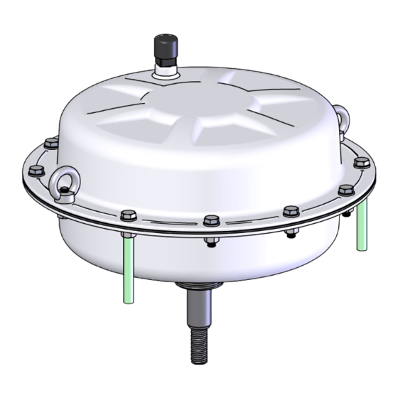
- Page 1 FlowAct IG - FCD VLENAI00IGA4 03/15 Assembly Instructions FlowAct IG IG 253, IG 503, IG 701 www.flowserve-villach.com...
- Page 2 FlowAct IG - FCD VLENAI00IGA4 03/15...
- Page 3 Technical Table A4 - Spring orientation Technical Table A5 - Spring packages Assembling Instruction - Valtek GS with FlowAct IG 253, 503, 701 - Spring to close - without Hand wheel 17 - 19 Assembling Instruction - Valtek GS with FlowAct IG 253, 503, 701 - Spring to open - without Hand wheel...
- Page 4 FlowAct IG - FCD VLENAI00IGA4 03/15 Pneumatic multi spring actuator - FlowAct order code Order code FlowAct Actuator design internal air supply Yoke design Multi-function yoke for GS only Actuator size 38.75 Stroke ( mm / inch ) 0.79 ( cm / inch 77.50 20, 40...
- Page 5 The diaphragm plate should be positioned to the diaphragm with the aid of the Positioning Template. • Turn clockwise the special nut (348) with the Special Tool using a suitable torque wrench. (See Page 13, Table A1) Marker Positioning Mark the position with a felt-tip pen. Window Template www.flowserve-villach.com...
- Page 6 FlowAct IG - FCD VLENAI00IGA4 03/15 Step Image Instruction • Lubricate the actuator stem with a suitable lubricant. (See Page 13, Table A3) • Lower the pre-assembled diaphragm-stem unit into the bottom diaphragm casing. Be careful not to score the stem. Positioning the diaphragm-stem unit such that the Drilling air connection and the mark match.
- Page 7 (351). • Install and finger tighten the hexagon bolts (335) and ring nuts (209). • Tighten the nuts (351) in four steps - 30 % 60 % 100 % and all around 100 % - using a crosswise pattern. (See Page 13, Table A2) • Install the vent plug (258). • Install the plastic pipe (339). • Mark and store the pre-assembled actuator body for further use. www.flowserve-villach.com...
- Page 8 FlowAct IG - FCD VLENAI00IGA4 03/15 Space for personal notes...
- Page 9 The diaphragm plate should be positioned to the diaphragm with the aid of the Positioning Template. • Turn clockwise the special nut (348) with the Special Tool using a suitable torque wrench. (See Page 13, Table A1) Positioning Marker Mark the position with a felt-tip pen. Window Template www.flowserve-villach.com...
- Page 10 FlowAct IG - FCD VLENAI00IGA4 03/15 Step Image Instruction • Install the spring adjusting plate (326). Positioning the spring adjusting plate such that the drilling, mark and air connection match. • Install the actuator springs (229). The springs have to be aligned. (See Page 13, Table 04) • Lubricate the actuator stem with a suitable lubricant. (See Page 13, Table A3) Drilling • Lower the pre-assembled diaphragm-stem unit into...
- Page 11 (351). • Install and finger tighten the hexagon bolts (335) and ring nuts (209). • Tighten the nuts (351) in four steps - 30 % 60 % 100 % and all around 100 % - using a crosswise pattern. (See Page 13, Table A2) • Install the vent plug (258). • Install the plastic pipe (339). • Mark and store the pre-assembled actuator body for further use. www.flowserve-villach.com...
- Page 12 FlowAct IG - FCD VLENAI00IGA4 03/15 Space for personal notes...
- Page 13 • The surface respectively the edges of Align this spring edge to the actuator center ! the spring ends should be aligned to the actuatos center. If these will ignored the spring may touch the actuators body and rub in rare cases. www.flowserve-villach.com...
- Page 14 FlowAct IG - FCD VLENAI00IGA4 03/15 FlowAct IG - Spring packages Table 05 Actuator size / Stroke Spring Spring range IG 253 IG 503 IG 701 Spring arrangement 0.787 0.787 1.574 0.787 1.574 2.362 psig 3 - 15 0,2 - 1,0 •...
- Page 15 FlowAct IG - FCD VLENAI00IGA4 03/15 www.flowserve-villach.com...
- Page 16 FlowAct IG - FCD VLENAI00IGA4 03/15...
- Page 17 (See Page 41, Table VA3) • Install the O-ring (278) onto the pre-assembled actuator body. • Install the O-ring (271) onto the yoke. • Lower the actuator body into the yoke. Be careful not to score the actuator stem • Install, finger tighten and fix the actuator lock nut (256). (See Page 41, Table VA1) www.flowserve-villach.com...
- Page 18 FlowAct IG - FCD VLENAI00IGA4 03/15 Step Image Instruction Move the actuator to the open position ! CRUSHING HAZARD ! Do not work between the yoke legs while the valve is in operation. • Connect the actuator with the air supply (less than 87 psig resp. 6 bar) and move it to the open position. • Mount the lock nut (344) and actuator coupling (249) onto the actuator stem.
- Page 19 • Remove one hexagon bolt (336, 351) and install the serial plate (252). • Tighten the nut (336, 351). (See Page 13, Table A2) • De-grease the adhesive surface and stick on the warning label (420) and the brand-name label (400) • The valve is ready for the mounting of the accessories. • Refer to the relevant manufacturer’s user instruction for information regarding other ancillary equipment. www.flowserve-villach.com...
- Page 20 FlowAct IG - FCD VLENAI00IGA4 03/15 Space for personal notes...
- Page 21 • Install the gasket (277) and screw plug (279) onto the yoke and tighten it clockwise. (See Page 41, Table VA2) • Install the O-ring (271) onto the yoke. • Lower the actuator body into the yoke. Be careful not to score the actuator stem • Install, finger tighten and fix the actuator lock nut (256). (See Page 41, Table VA1) www.flowserve-villach.com...
- Page 22 FlowAct IG - FCD VLENAI00IGA4 03/15 Step Image Instruction • Mount the lock nut (344) and actuator coupling (249) onto the actuator stem. • Justify the plug against the seat. • Adjust the distance between the valve coupling (345) and the actuator coupling (249) with the aid of an adapter in stroke height. Size Stroke 1/2” - 2” 15 - 50 0.787 +0.02 +0.5...
- Page 23 • Remove one hexagon bolt (335, 351) and install the serial plate (252). • Tighten the nut (335, 351). (See Page 13, Table A2) • De-grease the adhesive surface and stick on the warning label (420) and the brand-name label (400) • The valve is ready for the mounting of the accessories. • Refer to the relevant manufacturer’s user instruction for information regarding other ancillary equipment. www.flowserve-villach.com...
- Page 24 FlowAct IG - FCD VLENAI00IGA4 03/15 Space for personal notes...
- Page 25 Be careful not to score the actuator stem • Align the actuator in such a manner that the vent plug are left behind and the ribs of the actuator about paral- lel to the flow as shown. • Install, finger tighten and fix the actuator lock nut (256). (See Page 41, Table VA1) www.flowserve-villach.com...
- Page 26 FlowAct IG - FCD VLENAI00IGA4 03/15 Step Image Instruction Move the actuator to the open position ! CRUSHING HAZARD ! Do not work between the yoke legs while the valve is in operation. • Connect the actuator with the air supply (less than 87 psig resp. 6 bar) and move it to the open position. Danger of crushing ! Keep hands away from all moving parts.
- Page 27 Put yourself to the valves backside ! • Move the lever arms of the manual handwheel into the neutral position (393). • Positioning the manual handwheel on the yoke and connect them with the plain washers (140) and hex screws (150). Lock the lock nuts (140). • Perform one full stroke and check if its move smoothly. www.flowserve-villach.com...
- Page 28 FlowAct IG - FCD VLENAI00IGA4 03/15 Step Image Instruction • Remove one hexagon bolt (336, 351) and install the serial plate (252). • Tighten the nut (336, 351). (See Page 13, Table A2) 6.25 • De-grease the adhesive surface and stick on the warning label (420) and the brand-name label (400) • The valve is ready for the mounting of the accessories.
- Page 29 Be careful not to score the actuator stem • Align the actuator in such a manner that the vent plug are left behind and the ribs of the actuator about paral- lel to the flow as shown. • Install, finger tighten and fix the actuator lock nut (256). (See Page 41, Table VA1) www.flowserve-villach.com...
- Page 30 FlowAct IG - FCD VLENAI00IGA4 03/15 Step Image Instruction • Mount the lock nut (344) and actuator coupling (249) onto the actuator stem. • Justify the plug against the seat. • Adjust the distance between the valve coupling (345) and the actuator coupling (249) with the aid of an adapter in stroke height. Size Stroke 1/2” - 2” 15 - 50 0.787 +0.02 +0.5...
- Page 31 CRUSHING HAZARD ! Do not work between the yoke legs while the valve is in operation. • Disconnect the air supply so that it move to the open position. • Move the lever arms of the manual handwheel into the neutral position (393). • Positioning the manual handwheel on the yoke and connect them with the plain washers (140) and hex screws (150). • Perform one full stroke and check if its move smoothly. www.flowserve-villach.com...
- Page 32 FlowAct IG - FCD VLENAI00IGA4 03/15 Step Image Instruction • Remove one hexagon bolt (336, 351) and install the serial plate (252). • Tighten the nut (336, 351) (See Page 13, Table A2) • De-grease the adhesive surface and stick on the warning label (420) and the brand-name label (400) • The valve is ready for the mounting of the accessories.
- Page 33 Be careful not to score the actuator stem. • Align the actuator in such a manner that the vent plug are left behind and the ribs of the actuator about parallel to the flow as shown. • Install, finger tighten and fix the actuator lock nut (256). (See Page 41, Table VA1) www.flowserve-villach.com...
- Page 34 FlowAct IG - FCD VLENAI00IGA4 03/15 Step Image Instruction Move the actuator to the open position ! CRUSHING HAZARD ! Do not work between the yoke legs while the valve is in operation. • Connect the actuator with the air supply (less than 87 psig resp.
- Page 35 ! • Move the lever arms of the manual handwheel into the neutral position (393) • Positioning the manual handwheel on the yoke and connect them with the plain washers (140) and hex screws (150). Lock the lock nuts (140). • Perform one full stroke and check if its move smoothly. www.flowserve-villach.com...
- Page 36 FlowAct IG - FCD VLENAI00IGA4 03/15 Step Image Instruction • Remove one hexagon bolt (336, 351) and install the serial plate (252). • Tighten the nut (336, 351). (See Page 13, Table A2) • De-grease the adhesive surface and stick on the warning label (420) and the brand-name label (400) • The valve is ready for the mounting of the accessories.
- Page 37 Be careful not to score the actuator stem • Align the actuator in such a manner that the vent plug are left behind and the ribs of the actuator about parallel to the flow as shown. • Install, finger tighten and fix the actuator lock nut (256). (See Page 41, Table VA1) www.flowserve-villach.com...
- Page 38 FlowAct IG - FCD VLENAI00IGA4 03/15 Step Image Instruction • Mount the lock nut (344) and actuator coupling (249) onto the actuator stem. • Justify the plug against the seat. • Adjust the distance between the valve coupling (345) and the actuator coupling (249) with the aid of an adapter in stroke height. Size Stroke 1/2”...
- Page 39 • Disconnect the air supply so that it move to the open position. • Move the lever arms of the manual handwheel into the neutral position (393) • Positioning the manual handwheel on the yoke and connect them with the plain washers (140) and hex screws (150). • Perform one full stroke and check if its move smoothly. www.flowserve-villach.com...
- Page 40 FlowAct IG - FCD VLENAI00IGA4 03/15 Step Image Instruction • Remove one hexagon bolt (336, 351) and install the serial plate (252). • Tighten the nut (336, 351). (See Page 13, Table A2) • De-grease the adhesive surface and stick on the warning label (420) and the brand-name label (400) • The valve is ready for the mounting of the accessories.
- Page 41 (- 40 °C to + 70 °C) influenced medium and the medium for O-ring’s Klüber Unisilikon L250L temperature. for threads of the coupling parts Klüberalfa YV 93-1202 Klüberpaste 46 MR 401 for the thread of the stroke indicator bolting or equivalent www.flowserve-villach.com...
- Page 42 FlowAct IG - FCD VLENAI00IGA4 03/15 Special Tool Table ST1 Socket Spanner for SPECIAL NUT (348) Necessary tool for assembling and disassembling. For actuator type IG 253 Part # 327 589 For actuator type IG 503 + 701 Part # 327 590 Stem Clamping Tool for ACTUATOR STEM (211) Essential tool for assembling and disassembling.
-
Page 43: Parts List
6.50 O-Ring NBR 70 6.51 O-Ring NBR 70 Serial Plate Warning Label Brand-name Label see page 21 see page 22 see page 9 see page 23 Figure xx: Complete actuator parts (left - spring close, right - spring opens) www.flowserve-villach.com... - Page 44 Flowserve Corporation has established industry leadership in the design and manufacture of its products. When properly selected, this Flowserve Corporation product is designed to perform its intended function safely during its useful life. However, the purchaser or user of Flowserve Corporation products should be aware that Flowserve Corporation products might be used in numerous applications under a wide variety of industrial service conditions.
Need help?
Do you have a question about the FlowAct IG 253 and is the answer not in the manual?
Questions and answers