Table of Contents
Advertisement
Quick Links
Advertisement
Table of Contents

Subscribe to Our Youtube Channel
Related Manuals for Flowserve LTQ008 Series


Summary of Contents for Flowserve LTQ008 Series
- Page 1 LTQ008 – LTQ230 Series Installation Single-Phase and Low Voltage Products Operation Compact Quarter-Turn Electric Actuator Maintenance AIIOM000164-00 EN 20 Read these instructions prior to installing, operating, and maintaining this equipment.
- Page 2 LTQ008 – LTQ230 Series Single-Phase Products User Instructions – Copyright All rights reserved. No part of these instructions may be reproduced, stored in a retrieval system, or transmitted in any form or by any means without prior permission of Flowserve Corporation. Document Version...
-
Page 3: Table Of Contents
AIIOM000164 LTQ008 – LTQ230 Series Single-Phase Products User Instructions – TABLE OF CONTENTS General Information ......................4 1.1 Scope of Manual ..............................4 1.2 Disclaimer ................................4 1.3 Operational Concepts ............................4 Safety Information ......................6 2.1 Safety Symbols and Descriptions ........................6 2.2 Intended Use ...............................6 2.3 General Hazard Sources ...........................7 2.4 Qualified Personnel and Targeted Group .......................8 Product Description ...................... - Page 4 AIIOM000164 LTQ008 – LTQ230 Series Single-Phase Products User Instructions – 9.2 Calibration Procedure for Proportional Control (120 – 230 VAC Models) ..........30 9.3 Calibration Procedure for Proportional Control (12 – 24 VAC/VDC Models) ...........33 9.4 Calibration Procedure for LL Control Station Proportional Control ............35 9.5 Calibration Procedure for On/Off with Battery Backup ................36 10 Troubleshooting Guide ....................
-
Page 5: General Information
1.3 Operational Concepts The LTQ008 Series actuators are fully assembled, calibrated, and tested prior to leaving the factory. In most cases, after mounting the actuator to the desired device, it should be possible to operate the actuator from a fully CW (0°) to CCW (90°), and back again, finding that no adjustments are necessary. - Page 6 Despite all of Flowserve’s efforts to provide comprehensive information and instructions in this document on how to determine the various actuator levels, questions will arise. Contact Flowserve for further information before placing orders when unsure of the level of control required.
-
Page 7: Safety Information
- Installing, operating, or maintaining the product/system in any way that is not covered in this User Instruction could cause death, serious personal injury, or damage to the equipment. This includes any modification to the product/system or use of any parts not provided by Flowserve. Page 6 of 47... -
Page 8: General Hazard Sources
If the conditions of service on the purchase order change (e.g. pumping fluid, temperature, or duty conditions, etc.), it is imperative that the user seeks written agreement from Flowserve before start-up. Observe equipment labels, such as arrows designating the direction of rotation, warning signs, etc., and keep them in a legible condition. -
Page 9: Qualified Personnel And Targeted Group
AIIOM000164 LTQ008 – LTQ230 Series Single-Phase Products User Instructions – 2.3.2 Electrical Hazards - Risk of Electric Shock. Before working on any electrical equipment, turn off power supply to the equipment. All electrical wiring must be in conformance with applicable local codes, regulations, and the National Electric Code (NEC). -
Page 10: Product Description
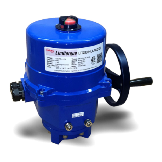
AIIOM000164 LTQ008 – LTQ230 Series Single-Phase Products User Instructions – 3 Product Description 3.1 General Product Description a) LTQ008 – LTQ203 The LTQ008 – LTQ017 Series are quarter-turn, electric industrial service actuators delivering up to 1770 lbf-in of torque with voltages ranging from 12V to 230V with on/off or proportional control modes. These NEMA 4X and IP67 compliant units are equipped with two volt-free Form A auxiliary switches rated at, up to, 10A 250VAC and a standard clutch-free, manual-override handwheel. -
Page 11: Shipping And Handling
AIIOM000164 LTQ008 – LTQ230 Series Single-Phase Products User Instructions – 3.2 Shipping and Handling This actuator arrives in the fully CW (0°) position. The red/green position indicator should show all red to denote this. The actuator has a red and green position indicator on the top of the unit. The red color in the indicator window means the actuator is fully CW (0°), while the green color means the actuator is fully CCW (90°). -
Page 12: Mounting
CW (0°) to the fully CCW (90°) position to check for unobstructed manual operation of the valve or damper. 5. The LTQ008 Series 3-phase actuators utilize a PCB to simply field wiring and testing. This PCB contains one of the terminal blocks. -
Page 13: Theory Of Operation
LTQ008 – LTQ230 Series Single-Phase Products User Instructions – 5 Theory of Operation Background: Flowserve offers several types of single-phase actuators that are designed to fit applications ranging from basic controls to fully-optioned solutions. These various strategies form the levels described below which allow a product to fit functionally and economically into most single-phase applications. -
Page 14: Ltq008 - Ltq203 Ncu (24V - 230V Proportional Control)
AIIOM000164 LTQ008 – LTQ230 Series Single-Phase Products User Instructions – 5.2 LTQ008 – LTQ203 NCU (24V – 230V Proportional Control) Inside the actuator/LCS package: 1. These models are designed to be used where there are no existing MCCs. Typically, these are used in new facilities, or where additions to existing switch gears have available space limitations or is otherwise just not feasible. -
Page 15: Ltq008 - Ltq203 Ll (24V - 230V On/Off Control)
AIIOM000164 LTQ008 – LTQ230 Series Single-Phase Products User Instructions – 5.3 LTQ008 – LTQ203 LL (24V – 230V On/Off Control) Inside the actuator/LCS package: 2. Integral Local Control Device. The design of this series allows for LOCAL mode (control knobs or buttons located on the face of the LCS, which is an integral part of the actuator) or REMOTE mode, which utilizes commands from a PLC, BAS, or other volt-free contact (dry contact) automation device. -
Page 16: Ltq008 - Ltq203 Ll (24V - 230V Proportional Control)
AIIOM000164 LTQ008 – LTQ230 Series Single-Phase Products User Instructions – 5.4 LTQ008 – LTQ203 LL (24V – 230V Proportional Control) These units accept analog control signals (4 – 20 mA or 2 – 10 VDC) and process these incoming signals to position the actuator as a function of the incoming signal. -
Page 17: Torque Switches
Torque Switch Operation The LTQ008 Series actuators have torque switches to protect the actuator, and any attached equipment, from possible damage that could occur in a high torque event. In such an event, the valve or damper bring driven encounters some blockage or impediment to travel. -
Page 18: Ltq Ll Series Lcs Operation
AIIOM000164 LTQ008 – LTQ230 Series Single-Phase Products User Instructions – 5.6 LTQ LL Series LCS Operation Operating the Local Control Station 1. The mode switch (right hand side) has three positions: i. STOP (center position) On/Off actuators: This position removes any ability to reposition the actuator electrically. -
Page 19: Battery Backup
LTQ008 – LTQ230 Series Single-Phase Products User Instructions – 6 Battery Backup 6.1 LTQ008-017 Battery The LTQ008 Series Battery Backup units are fitted with a battery storage enclosure mounted directly onto the actuator as shown. All wiring for the battery pack is complete and an internal disconnect for the battery system is provided. -
Page 20: Ltq034-088 Battery
AIIOM000164 LTQ008 – LTQ230 Series Single-Phase Products User Instructions – 6.2 LTQ034-088 Battery The LTQ034-088 Series Battery Backup units are fitted with a battery storage enclosure mounted to a bracket inside the actuator as shown. All wiring for the battery pack is complete and an internal disconnect for the battery system is provided. -
Page 21: 120/230V Transformer Mounting And Setup
AIIOM000164 LTQ008 – LTQ230 Series Single-Phase Products User Instructions – 6.3 120/230V Transformer Mounting and Setup Power Supply: The LTQ034 Series Battery Backup units require a 500VA 24vac / 20A 24vdc power supply directly into the actuator terminal block. To facilitate various site power availability, an optional enclosure is offered which houses an appropriately sized toroidal transformer to supply the 24V power to the actuator. -
Page 22: Adjustments
AIIOM000164 LTQ008 – LTQ230 Series Single-Phase Products User Instructions – 7 Adjustments This actuator arrives calibrated and tested by the factory to stop at 0° for the CW position and 90° for the CCW position. The auxiliary switch settings are based on the CW and CCW stops. Ideally, the auxiliary switches are set a few degrees in advance of the respective stop switches. -
Page 23: Adjusting Cw End-Of-Travel
AIIOM000164 LTQ008 – LTQ230 Series Single-Phase Products User Instructions – 7.1 Adjusting CW End-of-Travel 1. Reposition Mechanical Stop a. Disconnect power. b. Loosen the right-side mechanical stop. This is the CW mechanical stop limit adjustment. Using a 17 mm wrench and a 5 mm hex key, hold the jam nut and turn the stop screw 5 –... -
Page 24: Adjusting Ccw End-Of-Travel
AIIOM000164 LTQ008 – LTQ230 Series Single-Phase Products User Instructions – 7.2 Adjusting CCW End-of-Travel 1. Reposition Mechanical Stop a. Disconnect power. b. Loosen the left-side mechanical stop. This is the CCW mechanical stop limit adjustment. Using a 17 mm wrench and a 5 mm hex key, hold the jam nut and turn the stops screws 5 –... -
Page 25: Adjusting Auxiliary Switches
AIIOM000164 LTQ008 – LTQ230 Series Single-Phase Products User Instructions – 7.3 Adjusting Auxiliary Switches 1. Adjust CW auxiliary cams a. Cam 3 (red) and cam 5 (red) control the CW auxiliary switch adjustments. These are optional switches typically used to indicate when the actuator has reached its CW position. -
Page 26: Commissioning
AIIOM000164 LTQ008 – LTQ230 Series Single-Phase Products User Instructions – 8 Commissioning - The factory sets and tests the end-of-travel stops (cams) of this actuator to respond between 0° and 90° of rotation. If the end stops require no changes, this unit is ready for immediate operation using the following procedure. -
Page 27: Commissioning Procedure For Proportional Control
AIIOM000164 LTQ008 – LTQ230 Series Single-Phase Products User Instructions – 8.2 Commissioning Procedure for Proportional Control - Allowing the motor to drive the gear train into the mechanical stop will result in severe damage to the actuator! Remove power from this device before making any travel adjustments. After completing all mounting and wiring procedures, and main power is available, it is now possible to commission the actuator. -
Page 28: Commissioning Ll Control Station Proportional Control
AIIOM000164 LTQ008 – LTQ230 Series Single-Phase Products User Instructions – g. When the actuator reaches its fully CCW (90°) end-of-travel position, the OPEN LED indicator will stay illuminated on the face of the LCS. 5. Place the move switch in the CW (0°) position, and drive to approximately mid-travel, then stop. 6. - Page 29 AIIOM000164 LTQ008 – LTQ230 Series Single-Phase Products User Instructions – c. When the actuator reaches its fully CW (0°) end-of-travel position, the CLOSE LED indicator will stay illuminated on the face of the LCS. 6. Place the LCS move switch in the CCW (90°) position, and verify that the direction of the position indicator is CCW.
-
Page 30: Connecting And Starting The Battery System
AIIOM000164 LTQ008 – LTQ230 Series Single-Phase Products User Instructions – 8.5 Connecting and Starting the Battery System After the actuator has been fully installed in the field and wired to power and control systems, the unit is ready to initialize the battery system. The procedure is as follows: Remove the actuator top cover. -
Page 31: Calibration
AIIOM000164 LTQ008 – LTQ230 Series Single-Phase Products User Instructions – 9 Calibration 9.1 Calibration Procedure for On/Off Control - Allowing the motor to drive the gear train into the mechanical stop will result in severe damage to the actuator! Remove power from this device before making any travel adjustments. After completing all mounting and wiring procedures, and main power is available, it is now possible to commission the actuator. - Page 32 AIIOM000164 LTQ008 – LTQ230 Series Single-Phase Products User Instructions – a. The unit will run to its full CCW (90°) position, stop for a few seconds, then run back to its fully CW (0°) position. 11. After a few seconds, the unit will complete the calibration routine and return to active operation mode by responding to the...
- Page 33 AIIOM000164 LTQ008 – LTQ230 Series Single-Phase Products User Instructions – Figure 34: Proportional PCB details single-phase (120 – 230 VAC models) Page 32 of 47...
-
Page 34: Calibration Procedure For Proportional Control (12 - 24 Vac/Vdc Models)
AIIOM000164 LTQ008 – LTQ230 Series Single-Phase Products User Instructions – 9.3 Calibration Procedure for Proportional Control (12 – 24 VAC/VDC Models) - Allowing the motor to drive the gear train into the mechanical stop will result in severe damage to the actuator! Remove power from this device before making any travel adjustments. After completing all mounting and wiring procedures, and main power is available, it is now possible to commission the actuator. - Page 35 AIIOM000164 LTQ008 – LTQ230 Series Single-Phase Products User Instructions – Figure 37: Proportional PCB details single-phase (120 - 230 VAC models) Page 34 of 47...
-
Page 36: Calibration Procedure For Ll Control Station Proportional Control
AIIOM000164 LTQ008 – LTQ230 Series Single-Phase Products User Instructions – 9.4 Calibration Procedure for LL Control Station Proportional Control After completing all mounting and wiring procedures, and main power is available, it is now possible to commission the actuator. 1. Position the actuator to a mid-stroke position. 2. -
Page 37: Calibration Procedure For On/Off With Battery Backup
AIIOM000164 LTQ008 – LTQ230 Series Single-Phase Products User Instructions – 9.5 Calibration Procedure for On/Off with Battery Backup - Follow these directions carefully and in order. Actuator damage due to improper testing and commissioning will NOT be covered under warranty. After completing all mounting and wiring procedures and main power is available, it is now possible to commission the actuator. - Page 38 AIIOM000164 LTQ008 – LTQ230 Series Single-Phase Products User Instructions – Figure 42: Battery Backup Open/Close PCB details Page 37 of 47...
-
Page 39: Troubleshooting Guide
After completing all mounting and wiring procedures, and main power is available, if the actuator does not respond as expected, the following procedure(s) may help in identifying the problem. If problems still exist after consulting Table and Table , contact Flowserve for additional support. Table 2: Fault symptoms for on/off control models T h e a c t u a t o r d o e s n o t m o v e w h e n c o m m a n d e d t o d o s o . - Page 40 AIIOM000164 LTQ008 – LTQ230 Series Single-Phase Products User Instructions – Table 3: Fault symptoms for proportional control models T h e a c t u a t o r d o e s n o t m o v e w h e n c o m m a n d e d t o d o s o . ...
- Page 41 AIIOM000164 LTQ008 – LTQ230 Series Single-Phase Products User Instructions – Table 4: Fault symptoms for failsafe control models A c t u a t o r d o e s n o t m o v e t o e x p e c t e d F a i l - S a f e p o s i t i o n u p o n l o s s o f m a i n s p o w e r ...
-
Page 42: Technical Data
AIIOM000164 LTQ008 – LTQ230 Series Single-Phase Products User Instructions – 11 Technical Data 11.1 Nameplate Page 41 of 47... -
Page 43: Torque Requirements
AIIOM000164 LTQ008 – LTQ230 Series Single-Phase Products User Instructions – 11.2 Torque Requirements Table 2: LTQ008 – LTQ203 actuator specifications Actuator LTQ008 LTQ017 LTQ034 LTQ053 LTQ070 LTQ088 LTQ150 LTQ203 Supply Torque Output (in-lb / N m) 880 / 100 1770 / 200 3540 / 400 5310 / 600 7080 / 800... -
Page 44: Exploded View Of Ltq008 - Ltq203 Units
LTQ008 – LTQ230 Series Single-Phase Products User Instructions – AIIOM000164 11.3 Exploded View of LTQ008 – LTQ203 Units Figure 44: Exploded view of the LTQ008 – LTQ017 units... -
Page 45: Wire Sizing
11.4 Wire Sizing Wire sizing data is provided below to assist in the selection of the proper wire size for LTQ008 Series actuators using various wire sizes over distance. Always reference the correct voltage, and do not exceed the indicated length of the wire run for each model. - Page 46 LTQ008 – LTQ230 Series Single-Phase Products User Instructions – AIIOM000164 Table 9: Maximum distance between the actuator and power supply (ft) for 230 VAC units Actuator LTQ008 – LTQ017 LTQ034 – LTQ070 LTQ088 LTQ150 – LTQ203 Voltage 230 VAC 230 VAC 230 VAC 230 VAC Amps...
-
Page 47: Annex A: Glossary
LTQ008 – LTQ230 Series Single-Phase Products User Instructions – AIIOM000164 Annex A: Glossary Below are terms and definitions used throughout this manual: BAS is an industry acronym for a building automation system. BIC is an industry acronym for basic integral controls. CCW denotes the counter-clockwise direction for movement. - Page 48 Flowserve Corporation has established industry leadership in the design and manufacture of its products. When properly selected, this Flowserve product is designed to perform its intended function safely during its useful life. However, the purchaser or user of Flowserve products should be aware that Flowserve product might be used in numerous application under a wide variety of industrial service conditions.
Need help?
Do you have a question about the LTQ008 Series and is the answer not in the manual?
Questions and answers