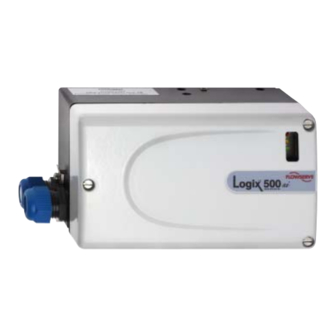
Summary of Contents for Flowserve Logix 510si
- Page 1 Logix 510si Digital Positioner This product meets the requirements of ADK041400E - 04.03...
-
Page 2: Table Of Contents
....................7 Wiring ....................8 Startup ....................8.1 Logix 510si Local Interface Operation ........8.2 Operation of Configuration Dipswitch Setup ......8.3 Setup of the Cal Dipswitches ............8.4 Quick-Cal Operation ..............8.5 Local Control of Valve Position ........... 8.6 Factory Reset ................ -
Page 3: General Information
USING FLOWSERVE VALVES, ACTUATORS AND ACCESSORIES CORRECTLY Protective clothing Using FLOWSERVE products are often used in problematic The following instructions are designed to assist in unpacking, installing and performing maintenance as applications (e.g. extremely high pressures, danger- ous, toxic or corrosive mediums). In particular valves required on FLOWSERVE products. -
Page 4: Unpacking
FLOWSERVE for repair or service FLOWSERVE must be provided with a certificate which confirms that the product has been decontaminated and is clean. STOP! FLOWSERVE will not accept deliveries if a certificate has not been provided (a form can be obtained from FLOWSERVE). Storage In most cases FLOWSERVE products are manufactured from stainless steel. -
Page 5: Logix 510Si Overview
LOGIX 510si OVERVIEW tor pressure rating a supply regulator is required to The Logix 510si is a two-wire, 4-20 mA input digital lower the pressure to the actuator’s maximum rating valve positioner. The Logix 510si positioner controls (not to be confused with operating range). A coa-... -
Page 6: Principle Of Operation
TUBING POSITIONER TO ACTUATOR PRINCIPLE OF OPERATION After mounting has been completed, tube the The Logix 510si positioner is a digital positioner with positioner to the actuator using the appropriate com- various options. The positioner consists of three main pression fitting connectors: modules: Air connections: 1/4”... -
Page 7: Wiring
The voltage 12,5 V is greater than the required 6.0 V; there- should be used to provide the unit with an adequate and reli- fore, this system will support the Logix 510si. The Logix 510si able earth ground reference. This ground should be tied to has an input resistance equivalent to 300 Ω... -
Page 8: Startup
3 LEDs on the local user interface. This docu- Auto Tune -This switch controls whether the posi- ment describes the setting and use of the Logix 510si tioner will auto tune itself every time the quick cal user interface. -
Page 9: Setup Of The Cal Dipswitches
If the rotary “Gain” selector switch is set to “E” tion. In the Jog mode the positioner waits for with the auto tune switch on, a Flowserve stan- the user to set the open and closed positions dard response tuning set will be calculated and ∆... -
Page 10: Quick-Cal Operation
WARNING: During the Quick-Cal operation the valve may stroke unexpectedly. Notify proper personnel that the valve will stroke, and make sure the valve is that the Logix 510si is only setting internal gain and properly isolated. direction of rotation parameters at this point the ac- tual span is set after the zero is set.) The valve will... - Page 11 indicating that it is waiting for the maximum signal to be input to the positioner. Normally this will be 20 mA, but if split range operation is required use the maximum current for the desired range. When the maximum signal value set at the desired value, press the ∆...
-
Page 12: Error Codes
9 STATUS CODES Logix 510si Status Condition Codes Colors Identifier Indication and resolution G - - - Any sequence starting with a Green light flashing first is a normal operating mode and indicates that there are no internal problems. GGGG No errors, alerts, or warnings. - Page 13 Logix 510si Status Condition Codes Colors Identifier Indication and resolution Y - - - Any sequence starting with a yellow light indicates that the unit is in a special calibration or test mode, or that there was a calibration problem.
-
Page 14: Version Number Checking
Logix 510si Status Condition Codes Colors Identifier Indication and resolution R - - - Any sequence starting with a red light indicates that there is an operational problem with the unit. RRYY Bad electronic assembly - replace. RGRR Position Deviation – Indicates that he position has exceeded a fixed 20% error between command and position for a period of time 5 times longer than the recorded stroke time. - Page 15 12 SPARE PART KITS Item No. Description Part-No. Cover Assembly Yellow White Black PC Board Assembly H10114000 PC Board Assembly with analog feedback H10114001 Repair kit for Logix 500-Relay Module Assembly H10011500 Repair kit for Potentiometer Assembly H10011600 Position Feedback Assembly H194500003 Follower Arm Assembly Max.
- Page 16 South Africa Saudi Arabia Telephone: +27 11 609 2094 Telephone: 9663 857 3442 Facsimile: +27 11 609 3735 Facsimile: 9663 859 5284 All data subject to change without notice ©04.2002 Flowserve Corporation. Flowserve and Kämmer are trademarks of Flowserve Corporation...


Need help?
Do you have a question about the Logix 510si and is the answer not in the manual?
Questions and answers