
Related Manuals for Flowserve Limitorque QX


Summary of Contents for Flowserve Limitorque QX
- Page 1 Limitorque QX Maintenance Electronic Actuator and Spare Parts FCD LMENIM3314-01 - 06/18 Experience In Motion...
-
Page 2: Table Of Contents
Limitorque QX Electronic Actuator FCD LMENIM3314-01 – 06/18 Contents Introduction 1.1 Premise 1.2 Procedure Emphasis 1.3 Important Notes and Warning Statement 1.4 Reference Documents 1.5 This Document Applies to both QX – 90˚ Actuators and All QXM-Multi-Turn Actuators QX Actuator Subassembly 2.1 QX Actuator Subassembly Components... - Page 3 Limitorque QX Electronic Actuator FCD LMENIM3314-01 – 06/18 4.7.1 Worm Shaft Assembly Removal 4.7.2 Worm Shaft Assembly Replacement 4.8 Drive Sleeve, Stops and Encoder Shaft Assemblies 4.8.1 Drive Sleeve, Mechanical Stops, Encoder Shaft Removal 4.8.2 Drive Sleeve, Mechanical Stops and Encoder Shaft Assembly Remounting 4.9 Optional Baseplate Assembly, F/FA-05 &...
- Page 4 Limitorque QX Electronic Actuator FCD LMENIM3314-01 – 06/18 Spares and Replacement Parts 8.1 Guidelines for Recommended Spare Parts 8.1.1 Wear Components 8.1.2 Bearings, O-rings, and Seals 8.1.3 Critical Components 8.2 Recommended Spare Parts for QX Actuators 8.2.1 Commissioning and Startup 8.2.2 Short-Term Duty...
-
Page 5: Motor Subassembly. Qx-1 Thru
Limitorque QX Electronic Actuator FCD LMENIM3314-01 – 06/18 Figure 4.28 Optional Thrust Base Subassembly Figure 5.1 90º Encoder Assembly Figure 5.2 Encoder To Subassembly, Item 14-1 Figure 5.3 Encoder To Unit Assembly View Figure 5.4 Multi-turn Encoder Assembly Figure 5.5 6.5-Turn Spur Gear Subassembly (Item 17-2) Figure 5.6 20-Turn Spur Gear Subassembly (Item 17-2) - Page 6 Limitorque QX Electronic Actuator FCD LMENIM3314-01 – 06/18 Table 4.10 Gearing and Clutching, QX-3 thru 5 Table 4.11 Clutch Shaft Subassembly, Item 6. QX-1 & 2 Table 4.12 Clutch Shaft Subassembly Item 6. QX-3 Thru 5 Table 4.13 Clutch Shaft Subassembly Item 7 Table 4.14 Pipe Plug...
-
Page 7: Introduction
Limitorque QX Electronic Actuator FCD LMENIM3314-01 – 06/18 Introduction 1.1 Premise The Flowserve Limitorque QX actuator components are separated into subassembly groupings. This manual covers the removal and remounting procedures for each subassembly group. Use these instructions when disassembly is required for service, maintenance or parts replacement. -
Page 8: Important Notes And Warning Statement
• QX Quick Mount and Start (Bulletin LMENIM3313) 1.5 This document applies to both QX – 90 degree actuators and all QXM-multi-turn actuators. The latest revisions to these documents are available on-line from Flowserve Limitorque’s website, www.flowserve. com or at www.limitorque.com... -
Page 9: Qx Actuator Subassembly
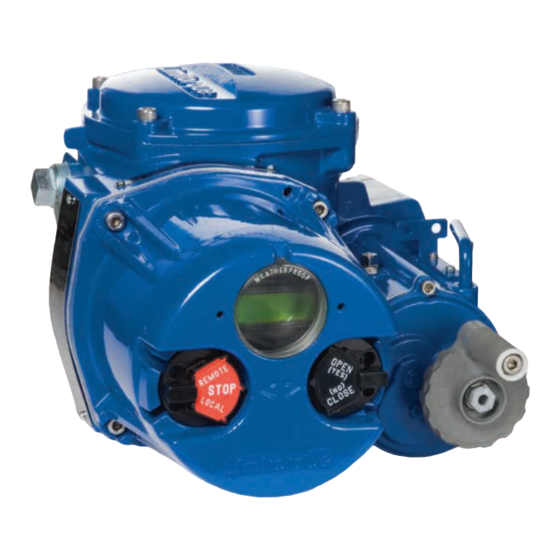
Limitorque QX Electronic Actuator FCD LMENIM3314-01 – 06/18 QX Actuator Subassembly Figure 2.1 - Typical QX Actuator 14-1 14-1 14-1 10-4 10-4 10-4 14-4 14-4 14-4 14-8 14-8 14-8 15-3 15-3 15-3 NOTE: QX-1 and 2 90° unit shown. flowserve.com... -
Page 10: Qx Actuator Subassembly Components
Limitorque QX Electronic Actuator FCD LMENIM3314-01 – 06/18 2.1 QX Actuator Subassembly Components Table 2.1 - Typical QX Actuator Subassembly Item Number Description Baseplate Motor cartridge Clutch shaft Clutch fork Handwheel cover 10-4 Handwheel Motor 14-1 Encoder 14-4 Terminal block... -
Page 11: Unit Weights
Limitorque QX Electronic Actuator FCD LMENIM3314-01 – 06/18 2.1.3 Unit Weights Table 2.2 - QX Unit Weights Unit QX-1 QX-2 QX-3 QX-4 QX-5 NOTE: Weights include B4 stem nut and lubricant. 2.2 Product Identification 2.2.1 Initial Inspection and Recording Suggestions Upon receipt of the actuator, several steps should be initially followed to ensure condition of equipment and to establish proper record keeping. -
Page 12: Maintenance
Limitorque QX Electronic Actuator FCD LMENIM3314-01 – 06/18 2.3 Maintenance 2.3.1 Recommended Maintenance Under normal operating conditions, the QX is a maintenance-free actuator. Therefore, for normal applications, the actuator will require no formal maintenance program. However, if the actuator is used under severe service conditions or operated in a Hazardous Location, the following maintenance procedures are required: 1. -
Page 13: O-Ring Lubrication
Limitorque QX Electronic Actuator FCD LMENIM3314-01 – 06/18 Figure 2.4 - QX Oil fill /Plug Locations (QX-1 thru 5) Oil plug OIL PLUG OIL PLUG top of unit TOP OF UNIT TOP OF UNIT Oil plug OIL PLUG OIL PLUG... -
Page 14: Returning Procedure
When parts are identified for warranty or other component replacement, a Return Material Authorization (RMA) must be obtained from Flowserve. Contact factory for a RMA number (see contact information in section 2.5.1). All returned parts must be accompanied by documentation with the following information to obtain credit for returned goods: •... -
Page 15: Remove Actuator From Mounting Adapter
Limitorque QX Electronic Actuator FCD LMENIM3314-01 – 06/18 Remove Actuator from Mounting Adapter 3.1 Actuator Removal with Type B4/B4E Base (Torque) 3.1.1 Removal (Type B4/B4E Base) Step 1 WARNING: Hazardous Voltage! Turn off all power sources to actuator before removing actuator from mounting plate. -
Page 16: Figure 3.2 - Torque Nut, F/Fa-05 And -07, Qx-1& 2 And F/Fa-10, Qx-1 Thru 5
Limitorque QX Electronic Actuator FCD LMENIM3314-01 – 06/18 Table 3.1 Torque Nut, F/FA-05 and -07, QX-1 & 2 and F/FA-10, QX-1 thru 5 ITEM NUMBER DESCRIPTION QTY. 13-7 SCOKET HEAD CAP SCREW 16-7 TORQUE NUT Figure 3.2 - Torque Nut, F/FA-05 and -07, QX-1& 2 and F/FA-10, QX-1 thru 5... -
Page 17: Actuator Removal With Type A1/A1E Base (Thrust)-Qxm Only
Limitorque QX Electronic Actuator FCD LMENIM3314-01 – 06/18 Step 6 Reconnect incoming power leads L1, L2, L3, and control wiring to the terminal block. Restore power source when ready for operation. 3.2 Actuator Removal with Type A1/A1E Base (Thrust) – QXM only 3.2.1 Optional Thrust Base Assembly QX-1 &... -
Page 18: Thrust Base Remounting
Limitorque QX Electronic Actuator FCD LMENIM3314-01 – 06/18 Table 3.3 - Optional Thrust Base Subassembly ITEM NUMBER DESCRIPTION QTY. 10-1 HOUSING, THRUST BASE 10-2 PILOT, THRUST BASE 10-3 THRUST NUT 10-6 SOCKET HEAD CAP SCREWS 10-7 FLAT WASHER 10-8 RELIEF FITTING... -
Page 19: Removal (Type A1/A1E Base) Actuator Removal Separate From Thrust Base
Limitorque QX Electronic Actuator FCD LMENIM3314-01 – 06/18 NOTE: Two procedure options are available for removing the actuator and the thrust base: Remove actuator from the thrust base, leaving the base mounted to the mounting flange or removing the thrust base separately Remove actuator and thrust base as a unit from the mounting flange. -
Page 20: Removal (Type A1/A1E Base) Actuator And Thrust Base As A Unit
Limitorque QX Electronic Actuator FCD LMENIM3314-01 – 06/18 STEP 9 WARNING: Hazardous Voltage! Turn off all power sources before rewiring incoming power leads L1, L2, L3, and control wiring in the terminal block. Reconnect incoming power leads L1, L2, L3, and control wiring to the terminal block. Restore power source when ready for operation. -
Page 21: Mechanical Assemblies
Limitorque QX Electronic Actuator FCD LMENIM3314-01 – 06/18 Mechanical Assemblies 4.1 Motor subassembly. QX-1 thru 5. NOTE: Proper motor testing is required when replacing motor. Consult your Limitorque representative or the Limitorque factory to replace with correct motor. Table 4.1 - Motor Parts List... -
Page 22: Figure 4.2 Motor Subassembly, Item11
Limitorque QX Electronic Actuator FCD LMENIM3314-01 – 06/18 4.1.1 Motor subassembly Removal. QX-1 thru 5. Step 1 WARNING: Hazardous Voltage! Turn off all power sources to actuator before removing motor assembly. Power sources may include main power or control power. -
Page 23: Figure 4.3 Motor Bracket Orientation View
Limitorque QX Electronic Actuator FCD LMENIM3314-01 – 06/18 4.1.2 Motor subassembly Remounting. QX-1 thru 5. Step 1 WARNING: Hazardous Voltage! Turn off all power sources to actuator before removing motor assembly. Power sources may include main power or control power. -
Page 24: Figure 4.4 Handwheel Cover Assembly
Limitorque QX Electronic Actuator FCD LMENIM3314-01 – 06/18 4.2 Handwheel cover subassembly, QX-1 thru 5. NOTE: Sections 4.2 – 4.8 require the actuator to be removed from the mounting plate and the oil drained. Table 4.3 - Handwheel Cover Assembly... -
Page 25: Figure 4.5 - Handwheel Cover Subassembly, Item 10. Qx-1 & 2
Limitorque QX Electronic Actuator FCD LMENIM3314-01 – 06/18 Table 4.4 - Handwheel Cover Subassembly Item 10. QX -1 & 2 ITEM NUMBER DESCRIPTION QTY. 10-1 COVER, HANDWHEEL 10-2 'O'-RING 10-3 SHAFT, HANDWHEEL 10-4 HANDWHEEL SUBASSEMBLY 10-5 RETAINING RING Figure 4.5 - Handwheel Cover Subassembly, Item 10. QX-1 & 2... -
Page 26: Figure 4.6 - Handwheel Cover Subassembly, Item 10. Qx-3 Thru 5
Limitorque QX Electronic Actuator FCD LMENIM3314-01 – 06/18 Figure 4.6 - Handwheel Cover Subassembly, Item 10. QX-3 thru 5 10-3 10-3 10-5 10-5 10-2 10-2 10-1 10-1 10-4 10-4 10-5 10-5 10-6 10-6 Table 4.6 - Handwheel Subassembly, Item 10-4 ITEM NUMBER QTY. -
Page 27: Handwheel Cover Assembly Remounting
Limitorque QX Electronic Actuator FCD LMENIM3314-01 – 06/18 4.2.2 Handwheel Cover Assembly Remounting Step 1 Lightly lubricate ‘O’-ring (#15-2) and install around handwheel cover subassembly pilot (#10). Slide ball bearing (#9-13) back on end of clutch assembly if bearing was removed. Slide handwheel cover assembly pilot (#10) into the unit housing assuring the ball bearing aligns in handwheel shaft bore and dowel pin (13-1) aligns with the pin hole in cover. -
Page 28: Motor Cartridge Assembly Remounting
Limitorque QX Electronic Actuator FCD LMENIM3314-01 – 06/18 Table 4.8 - Motor Cartridge Subassembly, Item 5 ITEM NUMBER DESCRIPTION QTY. BUSHING BALL BEARING OIL SEAL SHAFT SPIRAL PIN PINION, MOTOR SPIRAL PIN 'O'-RING Figure 4.9 - Motor Cartridge Subassembly, Item 5 4.3.2 Motor Cartridge Assembly Remounting. -
Page 29: Gearing And Clutching
Limitorque QX Electronic Actuator FCD LMENIM3314-01 – 06/18 4.4 Gearing and Clutching. NOTE: Sections 4.2 – 4.8 require the actuator to be removed from the mounting plate and the oil drained. Table 4.9 - Gearing and clutching, QX-1 & 2... -
Page 30: Figure 4.11 - Gearing And Clutching, Qx-3 Thru 5
Limitorque QX Electronic Actuator FCD LMENIM3314-01 – 06/18 Table 4.10 - Gearing and clutching, QX-3 thru 5 ITEM NUMBER DESCRIPTION QTY. CLUTCH SHAFT SUBASSEMBLY CLUTCH FORK SUBASSEMBLY SPUR IDLER SUBASSEMBLY PLATE, GEAR SOCKET HEAD FLAT SCREW BRACKET, DECLUTCH SOCKET HEAD FLAT SCREW... -
Page 31: Gearing And Clutching Removal
Limitorque QX Electronic Actuator FCD LMENIM3314-01 – 06/18 4.4.1 Gearing and Clutching Removal. WARNING: Potential to operate while dangerous mechanical parts are exposed during subassembly removal. To prevent injury, turn off all power sources to actuator before removing top-mounted handwheel assembly. -
Page 32: Figure 4.12 - Clutch Shaft Subassembly, Item 6. Qx-1 & 2
Limitorque QX Electronic Actuator FCD LMENIM3314-01 – 06/18 Figure 4.12 - Clutch Shaft Subassembly, Item 6. QX-1 & 2 Table 4.12 - Clutch Shaft Subassembly Item 6. QX-3 Thru 5 ITEM NUMBER DESCRIPTION QTY. CLUTCH SHAFT MOTOR CLUTCH GEAR CLUTCH... -
Page 33: Gearing And Clutching Remounting
Limitorque QX Electronic Actuator FCD LMENIM3314-01 – 06/18 Table 4.13 - Clutch Shaft Subassembly Item 7 ITEM NUMBER DESCRIPTION QTY. CLUTCH FORK BUSHING LATCH SOCKET HEAD CAP SCREW TORSION SPRING WASHER SOCKET HEAD CAP SCREW Figure 4.14 - Clutch Shaft Subassembly, Item 7 4.4.2 Gearing and Clutching Remounting. -
Page 34: Figure 4.15 Clutch Fork Shaft Remounting
Limitorque QX Electronic Actuator FCD LMENIM3314-01 – 06/18 Figure 4.15 - Clutch Fork Shaft Remounting Latch To Gear Face LATCH TO GEAR FACE 9-13 9-13 Step 5, Declutch lever and spring return assembly. Lightly lubricate ‘O’-ring (#9-8) and slide over declutch lever (#9-9). Slide declutch lever and ‘O’-ring thru housing bore and down thru clutch fork bore and into the housing bore on other side ensuring that lever handle is installed properly with declutch bracket (#9-6), lever should not swing outwards. -
Page 35: Pipe Plug
Limitorque QX Electronic Actuator FCD LMENIM3314-01 – 06/18 4.5 Pipe Plug NOTE: Sections 4.2 – 4.8 require the actuator to be removed from the mounting plate and the oil drained. Table 4.14 - Pipe Plug ITEM NUMBER DESCRIPTION QTY. 12-1 PIPE PLUG Figure 4.17 Pipe Plug... -
Page 36: Figure 4.18 - Baseplate, F/Fa-10 Qx-1 & 2, F/Fa-12 & 14, Qx-3 Thru 5
Limitorque QX Electronic Actuator FCD LMENIM3314-01 – 06/18 Table 4.15 Baseplate F/FA-10 QX-1 & 2, F/FA-12 & 14 QX-3 thru 5 ITEM NUMBER DESCRIPTION QTY. BASEPLATE ASSEMBLY 'O'-RING SOCKET HEAD CAP SCREWS Figure 4.18 - Baseplate, F/FA-10 QX-1 & 2, F/FA-12 & 14, QX-3 thru 5 Step 1 Using a M8 hex key, remove the M10 screws (#4-2) and remove baseplate (#3). -
Page 37: Baseplate Remounting
Limitorque QX Electronic Actuator FCD LMENIM3314-01 – 06/18 4.6.2 Baseplate Remounting. Step 1 Lightly lubricate ‘Q’-ring (#3-2) and install in baseplate subassembly groove. Lightly lubricate ‘O’-ring (#4-1) and install around baseplate subassembly pilot (#3). Slide baseplate subassembly into housing and over drive sleeve (#1-1). Fit the screws (#4-2) (Qty of 4 for QX-1 &... -
Page 38: Worm Shaft Assembly Removal
If replacing worm shaft, thrust bearing and needle bearing this step is not needed. 4.7.2 Worm Shaft Assembly Replacement. CAUTION: Flowserve Limitorque recommends that the factory be contacted at 434-528-4400 to arrange replacement of a QX worm shaft at an authorized service center. Special tools are required for replacement. - Page 39 Place washer (#2-4) over end of worm shaft making sure that the chamfer on washer is facing out (Away from thrust bearing). Using special tools from Flowserve slip on round retaining ring (#2-5). Retaining ring must engage in worm shaft round groove and fit inside the chamfer on washer (#2-4).
-
Page 40: Figure 4.21 Drive Sleeve, Stops, And Encoder Shaft Assembly
Limitorque QX Electronic Actuator FCD LMENIM3314-01 – 06/18 4.8 Drive Sleeve, Stops and Encoder Shaft Assemblies NOTE: Sections 4.2 – 4.8 require the actuator to be removed from the mounting plate and the oil drained Table 4.18 - Drive Sleeve, Stops, and Encoder Shaft Assembly... -
Page 41: Drive Sleeve, Stops And Encoder Shaft Assemblies
Limitorque QX Electronic Actuator FCD LMENIM3314-01 – 06/18 4.8.1 Drive Sleeve, Mechanical Stops, Encoder Shaft Removal. NOTE: Baseplate (#3) must be removed to remove drive sleeve, see step 4-6-1. Washer ((#1-8) and needle bearing (#1-9) removed in section 4-7-1 step 2 when removing worm shaft. -
Page 42: Drive Sleeve, Mechanical Stops And Encoder Shaft Assembly Remounting
Note that this washer is needed if worm shaft is to be removed at any time in the future. Lubricate needle bearing (#1-9) and using special tools from Flowserve lightly press or hammer needle bearing into housing until seated. -
Page 43: Optional Baseplate Assembly, F/Fa-05 & -07 Qx-1 & 2, F/Fa-10 Qx-3 Thru
Limitorque QX Electronic Actuator FCD LMENIM3314-01 – 06/18 4.9 Optional Baseplate Assembly, F/FA-05 & -07 QX-1 & 2, F/FA-10 QX-3 thru 5. 4.9.1– Optional Baseplate Removal. Table 4.20 - Optional Baseplate Removal ITEM NUMBER DESCRIPTION QTY. 16-2 BASEPLATE 16-3 SOCKET HEAD CAP SCREWS Figure 4.24 - F/FA-05 / 07, QX-1 &... -
Page 44: Torque Nut
Limitorque QX Electronic Actuator FCD LMENIM3314-01 – 06/18 4.10 Torque Nut. Table 4.21 - Torque nut, F/FA-10, QX-1 & 2 and F/FA-12 and -14, QX-1 thru 5 ITEM NUMBER DESCRIPTION QTY. 13-6 TORQUE NUT 13-7 SCO HEAD CAP SCREW Figure 4.25 - Torque nut, F/FA-10, QX-1 & 2 and F/FA-12 and -14, QX-1 thru 5... -
Page 45: Optional Small Baseplate Removal
Limitorque QX Electronic Actuator FCD LMENIM3314-01 – 06/18 4.10.1 Optional Small Baseplate Removal. Step 1 QX-1 & 2, F/FA-10 and QX-3 thru 5 F/FA-12 and -14. Using a M3 hex key forQX-1 & 2 or M5 hex key for QX-3, 4 & 5, remove the M4 or M6 screws (#13-7) and remove torque nut (#13-6). -
Page 46: Optional Thrust Base Assembly Removal
Limitorque QX Electronic Actuator FCD LMENIM3314-01 – 06/18 4.11.1 Optional Thrust Base Assembly Removal. Step 1 Remove the four (4) screws (# ) and remove the thrust base subassembly (#16-17) by sliding the base down. If base is ISO remove the spacer (pilot) (#16-16). -
Page 47: Thrust Base Remounting
Limitorque QX Electronic Actuator FCD LMENIM3314-01 – 06/18 4.11.2 Thrust Base Remounting. Step 1 Place QX torque nut (#16-10) into unit drive sleeve (#1-11) aligning nut lugs to drive sleeve slots. Step 2 Lightly lubricate ‘O’-rings (#16-12) and (#16-13) and insert into bushing (#16-11) that is pressed into adapter plate (#16-14). -
Page 48: Encoder Assemblies
Limitorque QX Electronic Actuator FCD LMENIM3314-01 – 06/18 Encoder Assemblies 5.1 Encoder 90 Degree Unit Removal. QX-1 thru 5 Table 5.1 - 90º Encoder Assembly ITEM NUMBER DESCRIPTION QTY. 14-1 ENCODER ASSEMBLY 14-2 SOCKET HEAD CAP SCREWS Figure 5.1 90º Encoder Assembly... -
Page 49: Degree Encoder Remounting
Limitorque QX Electronic Actuator FCD LMENIM3314-01 – 06/18 Table 5.2 - Encoder Subassembly, Item 14-1 ITEM NUMBER DESCRIPTION QTY. ENCODER BOARD ROTOR STANDOFF SELF TAP OVAL HEAD SCREWS Figure 5.2 - Encoder To Subassembly, Item 14-1 5.1.2 90 Degree Encoder Remounting... -
Page 50: Multi Turn Encoder. Qxm-1 Thru 5, All Rpms
Limitorque QX Electronic Actuator FCD LMENIM3314-01 – 06/18 5.2 Multi Turn Encoder. QXM-1 thru 5, all RPMs Table - 5.3 Multi-Turn Encoder Assembly DESCRIPTION DESCRIPTION QTY. QTY. ITEM NUMBER (6.5 TURN) (20 TURN) (QX-1 &2) (QX-3 THRU 5) 17-1 DOWEL PIN... -
Page 51: Figure 5.5 6.5-Turn Spur Gear Subassembly (Item 17-2)
Limitorque QX Electronic Actuator FCD LMENIM3314-01 – 06/18 NOTE: For the 20 turn encoder assembly the slots in the big gear must be aligned with the top and bottom plate to access screws (#17-5). To do this the encoder shaft and/or drive sleeve must be rotated to the correct position aligning slots. -
Page 52: Multi Turn Encoder Remounting
Limitorque QX Electronic Actuator FCD LMENIM3314-01 – 06/18 Figure 5.6 - 20-Turn Spur Gear Subassembly (Item 17-2) See note 3 SEE NOTE 3 5.2.2 Multi Turn Encoder Remounting Step 1 Slide the encoder spur assembly (#17-2) into housing thru housing controls area bore and down over the multi turn encoder shaft pinion. - Page 53 Limitorque QX Electronic Actuator FCD LMENIM3314-01 – 06/18 Note: The encoder rotor can only be mated to the encoder shaft in one position. The encoder shaft has 3 flats that must align correctly to the encoder rotor ID and ribs. See Figure 5.3 for reference.
-
Page 54: Electronic Assemblies
Limitorque QX Electronic Actuator FCD LMENIM3314-01 – 06/18 Electronic Assemblies 6.1 Terminal Cover Table 6.1 - Terminal Cover Assembly ITEM NUMBER DESCRIPTION QTY. 15-5 TERMINAL COVER SUBASSEMBLY 15-6 SOCKET HEAD CAP SCREWS Figure 6.1 - Terminal Cover Assembly 15-5 15-5... -
Page 55: Terminal Cover Remounting
Limitorque QX Electronic Actuator FCD LMENIM3314-01 – 06/18 Table 6.2 - Terminal Cover Subassembly ITEM NUMBER DESCRIPTION QTY. 8-12 TERMINAL COVER 8-13 O'-RING 8-27 LABEL, TERMINAL BLOCK 8-28 HOOK 8-29 LOOP Figure 6.2 - Terminal Cover Subassembly 8-28 8-28 8-29... -
Page 56: Controls Cover Removal
Limitorque QX Electronic Actuator FCD LMENIM3314-01 – 06/18 Figure 6.3 - Controls Cover Assembly 15-3 15-3 15-6 15-6 6.2.1 Controls Cover Removal Step 1 Using a M6 hex key, remove the four M8 screws (#15-6) that mount the Controls cover subassembly and remove cover (#15-3). -
Page 57: Controls Cover Subassembly Remounting
Limitorque QX Electronic Actuator FCD LMENIM3314-01 – 06/18 Figure 6.4 - Controls Cover Subassembly 7-44 7-44 7-14 7-14 7-20 7-20 7-19 7-19 7-12 7-12 8-24 8-24 7-18 7-18 1-49 1-49 7-17 1-46 1-46 7-17 7-17 7-17 7-21 7-21 6.2.2 Controls Cover Subassembly Remounting Step 1 Lightly lubricate ‘O’-ring (#7-21) and install around controls cover spigot/pilot (#7-17). -
Page 58: Control Module Subassemblies
Limitorque QX Electronic Actuator FCD LMENIM3314-01 – 06/18 Figure 6.5 - Control Module Assembly 14-9 14-9 14-8 14-8 14-12 14-11 14-11 14-12 6.3.1 Control Module Removal Step 1 Using a M3 hex key remove screw (# 14-12) and retainer (#14-11 ). Disconnect all wiring harnesses. -
Page 59: Figure 6.6 Low Voltage (Less Than 250 Vac) Control Module Subassembly
Limitorque QX Electronic Actuator FCD LMENIM3314-01 – 06/18 Figure 6.6 - Low Voltage (Less than 250 VAC) Control Module Subassembly 1-18 1-18 1-10 1-10 Table 6.7 - High Voltage (Greater than 250 VAC) Control Module Subassembly ITEM NUMBER DESCRIPTION QTY. -
Page 60: Figure 6.8 Dcv Control Module Subassembly
Limitorque QX Electronic Actuator FCD LMENIM3314-01 – 06/18 Table 6.8 - DCV Control Module Subassembly ITEM NUMBER DESCRIPTION QTY. FLAT WASHER HEX STANDOFF, SHORT HEX STANDOFF, LONG PVC TUBE DC BOARD SOCKET HD CAP SCREWS BRACKET, CONNECTOR RETAINER (OPTIONAL) WIRING HARNESS Figure 6.8 - DCV Control Module Subassembly... -
Page 61: Control Module Remounting
Limitorque QX Electronic Actuator FCD LMENIM3314-01 – 06/18 6.3.3 Control Module Remounting Step 1 Position the controls module subassembly over the three mounting screw heads (#14-9). Rotate the subassembly in a clockwise (CW) direction until all three screws are seated in the keyhole slots. -
Page 62: Terminal Block Shield
Limitorque QX Electronic Actuator FCD LMENIM3314-01 – 06/18 Figure 6.10 - Terminal Blockm Assembly 14-3 14-3 14-5 14-5 14-4 14-4 6.4.1 Terminal Block Shield Figure 6.11 - Terminal Block Shield M3 x 5 self lock screw Shield-terminal block M3 X 5 SELF LOCK SCREW SHIELD-TERMINAL BLOCK Use qty. - Page 63 Limitorque QX Electronic Actuator FCD LMENIM3314-01 – 06/18 A shield must be installed on the last board fitting between the last option board and the power board. See Figure 6.14 for illustration. A maximum of four option boards can be used per unit, barring other restrictions. A four option board stack requires four (4) M4x70 pan head screws.
-
Page 64: Figure 6.12 Quik Power Without Option Boards
Limitorque QX Electronic Actuator FCD LMENIM3314-01 – 06/18 Connect to the control cover using four (4) M4x40pan head screws. Ensure that primary board jumper (board “A”) is in the “A” position and redundant board jumper (board “B”) is in the “B” position. Connect the J7 6-pin cable from the terminal block to socket J8 on the “A”... -
Page 65: Figure 6.13 Quik Power With Option Boards
Limitorque QX Electronic Actuator FCD LMENIM3314-01 – 06/18 Installation with option boards: 1. Move JP1 jumper to the ‘NORM’ position 2. Insert PCB standoffs on populated side of board in holes marked ‘A’ as shown in Figure 6.13. 3. Mount board at end of board stack, plugging ribbon cable into the J2 receptacle on main board as shown Figure 6.13 - Quik Power With Option Boards... -
Page 66: Figure 6.14 Option Board Assembly
Limitorque QX Electronic Actuator FCD LMENIM3314-01 – 06/18 STEP 12 – ALIGNMENT OF OPTION BOARDS INTO LCS/MAIN BOARD Line up screw sockets and stack the boards so that J7 (option board pins and sockets) fits in with the main board or any boards that are installed previously. -
Page 67: Removal
Limitorque QX Electronic Actuator FCD LMENIM3314-01 – 06/18 Table 6.11 - Screw Part Numbers BOARD DESCRIPTION SCREW PART NUMBER DESCRIPTION QTY. MAIN WITH 64-818-0001-35 M4X8 NO OPTION BOARDS MAIN WITH 64-818-0001-32 M4X25 1 OPTION BOARD MAIN WITH 64-818-0001-36 M4X40 2 OPTION BOARDS... -
Page 68: Optional Transformer Removal
Limitorque QX Electronic Actuator FCD LMENIM3314-01 – 06/18 6.6.1 Optional Transformer Removal WARNING: Hazardous Voltage! Turn off all power sources to actuator before removing control module assembly. Power sources may include main power or control power. CAUTION: Potential to cause electrostatic damage to electronic components. Before handling electronic components, ensure that you are discharged of static electricity by briefly touching a grounded metal object. -
Page 69: Optional Transformer Remounting
Limitorque QX Electronic Actuator FCD LMENIM3314-01 – 06/18 6.6.2 Optional Transformer Remounting Step 1 Position optional transformer assembly (#1) to the 4 M3 taps on the back of the control module chassis plate, see Figure 6.16 for orientation. Fit the four M3 screws (#2) thru bracket holes aligning with the taps in on the control module and using a M2.5 hex key tighten the four M3 screws. -
Page 70: Electronic Wiring (Cabling)
Limitorque QX Electronic Actuator FCD LMENIM3314-01 – 06/18 Electronic Wiring (Cabling) 7.1 AC Low Voltage Wiring (Cabling) Quick Reference Guide for Control Module and Main Board. (Less than 250 VAC) 7.1.1 AC Low Voltage Module (Version 1). Figure 7.1 is a diagram that shows wiring locations for a low voltage QX unit with version 1 motor controller board. -
Page 71: Ac Low Voltage Module (Version 2)
Limitorque QX Electronic Actuator FCD LMENIM3314-01 – 06/18 7.1.2 AC Low Voltage Module (Version 2). Figure 7.2 is a diagram that shows wiring locations for a low voltage QX unit with version 2 motor controller board. Motor controller board part number 68-825-0012. -
Page 72: Optional Transformer Wiring (Cabling) Quick Reference Guide
Limitorque QX Electronic Actuator FCD LMENIM3314-01 – 06/18 Figure 7.4 - High Voltage QX Unit Wiring Terminal block 3 pin connector (J9) TERMINAL BLOCK 3 PIN CONNECTOR (J9) To toroid transformer black-black TO TOROID TRANSFORMER BLACK-BLACK WIRES, 3 PIN CONNECTOR... -
Page 73: Optional Transformer Harness Wiring Used With High Voltage Control Module
Limitorque QX Electronic Actuator FCD LMENIM3314-01 – 06/18 7.3.1 Optional Transformer Harness Wiring Used With Low Voltage Control Module Figure 7.6 - Optional Low Voltage Transformer Harness Wiring To optional transformer TO OPTIONAL TRANSFORMER To high voltage TO HIGH VOLTAGE... -
Page 74: Terminal Block Wiring Harness Numbers
Limitorque QX Electronic Actuator FCD LMENIM3314-01 – 06/18 Figure 7.9 - Optional Transformer Harness Connector to Wire Position per Supply Voltage Pin number PIN NUMBER 1 See table for wire and socket pin SEE TABLE FOR WIRE AND SOCKET PIN... -
Page 75: Spares And Replacement Parts
8.1.3 Critical Components The following parts are not subject to wear but are still recommended for stock due to their critical nature. Flowserve recommends stock levels of between 5% and 10% of the total population of each part with a minimum of one of each in order to support the product for life. -
Page 76: Recommended Spare Parts For Qx Actuators
Limitorque QX Electronic Actuator FCD LMENIM3314-01 – 06/18 8.2 Recommended Spare Parts for QX Actuators 8.2.1 Commissioning and Startup No additional spare parts are required. All necessary spares are included in the end-user bag. 8.2.2 Short-Term Duty This is defined as up to 5000 seats or up to 1 million drive sleeve operations, whichever occurs first. There are no spare parts required for the actuator during short-term duty. -
Page 77: Other Concerns
5. Regular testing 8. Stall/overload condition Flowserve strongly recommends using OEM parts to support and maintain your QX actuator. Installing parts other than genuine Flowserve Limitorque parts could cause premature failure of your actuator and voids any remaining warranty. The above guidelines are provided to assist you in determining your unique spare parts needs. Please contact your local Limitorque Sales Office or local Authorized Stocking Distributor for additional help in evaluating your needs. -
Page 78: Regulatory Information
Limitorque QX Electronic Actuator FCD LMENIM3314-01 – 06/18 Regulatory Information 9.1 Declaration of Conformity Application of Council Directive(s) 2004/108/EC; EMC Directive 2006/42/EC; Machinery Directive 2003/10/EC; Airborne Noise Directive 94/9/EC; ATEX Directive Standard(s) to which Conformity is Declared Machinery; EN 60204-1 EMC - Emissions;... - Page 79 Limitorque QX Electronic Actuator FCD LMENIM3314-01 – 06/18 EMC - Electromagnetic Compatibility (EMC) and Electromagnetic Interference (EMI) standards to which this actuator complies: APPLICABLE EMISSIONS EN50011:1998 CLASS A SERVICE STANDARDS 30-130MHz EN55011:1998 & 40dBmV / m Radiated emissions FCC Part 15, subpart J...
-
Page 80: Specific Conditions For Use - Atex/Cenelec/Iecex Applications
3. Consult the manufacturer if dimensional information on the flameproof joints is necessary. 9.3 Statement of Compliance with Applicable European Directives We, Flowserve Limitorque, 5114 Woodall Road, Lynchburg, VA, USA 24502, as the manufacturer of the equipment listed below: QX-1, 2, 3, 4, 5 electronic valve actuator. The QX is a non-intrusive electronic actuator. It is specifically designed for the purpose of being mounted to a quarter turn valve (or other apparatus) in order to move the valve from fully closed to fully open. - Page 81 Limitorque QX Electronic Actuator FCD LMENIM3314-01 – 06/18 Confirm, in accordance with the requirements of clause 1.2.7 of the Essential Health and Safety Requirements of Community Directive 94/9/EC on equipment and protective systems intended for use in potentially explosive atmospheres that the above equipment has been designed and manufactured to: a) Avoid physical injury or other harm which may be caused by direct or indirect contact;...
- Page 82 Flowserve Corporation has established industry leadership in the design and manufacture of its products. When properly selected, this Flowserve product is designed to perform its intended function safely during its useful life. However, the purchaser or user of Flowserve products should be aware that Flowserve products might be used in numerous applications under a wide variety of industrial service conditions.
Need help?
Do you have a question about the Limitorque QX and is the answer not in the manual?
Questions and answers