
Related Manuals for Flowserve Limitorque MX-40


Summary of Contents for Flowserve Limitorque MX-40
- Page 1 Swanson Flo | 800-288-7926 | www.swansonflo.com USER INSTRUCTIONS Limitorque MX Maintenance and Spare Parts Electronic Actuator FCD LMENIM2314-00 – 07/08 Experience In Motion...
- Page 2 Swanson Flo | 800-288-7926 | www.swansonflo.com...
-
Page 3: Table Of Contents
4.4 Side-Mounted Handwheel Without Spur Gear Attachment (MX-10, -20, -85, -140, and -150) 4.4.1 Side-Mounted Handwheel Without Spur Gear Attachment (MX-85, -140, and -150) 4.4.2 Removal of Side-Mounted Handwheel (MX-10, -20, -85, -140, and -150) 4.4.3 Removal 4.4.4 Remounting flowserve.com... - Page 4 Swanson Flo | 800-288-7926 | www.swansonflo.com Limitorque MX Maintenance and Spare Parts FCD LMENIM2314-00 – 07/08 4.5 Side-Mounted Handwheel With Spur Gear Attachment (MX-40, -85, -140, and -150) 4.5.1 MX-85, -140, and -150 Handwheel with SGA 4.5.2 Removal of Handwheel 4.5.3 Removal 4.5.4 Remounting 4.6 Converting Top-Mounted Handwheel to Side-Mounted Handwheel (MX-10, -20, and -40)
- Page 5 5.18 Solid State Motor Reverser Upgrade Instructions (Most units prior to September 2007) 5.18.1 Disassembly Procedure 5.18.2 Assembly Procedure 5.19 Mounting of SSMR (Solid State Motor Reverser) in units shipped after February 2008 5.20 Complete Conversion to SMT Controls flowserve.com...
- Page 6 Swanson Flo | 800-288-7926 | www.swansonflo.com Limitorque MX Maintenance and Spare Parts FCD LMENIM2314-00 – 07/08 Spare and Replacement Parts 6.1 Guidelines for Recommended Spare Parts 6.1.1 Wear Components 6.1.2 Bearings, O-rings, and Seals 6.1.3 Critical Components 6.2 Recommended Spare Parts for MX Actuators 6.2.1 Commissioning and Startup 6.2.2 Short-Term Duty 6.2.3 Long-Term Duty...
- Page 7 Table 4.9 – Side-Mounted Handwheel without Spur Gear Attachment Parts List (MX-85, -140, and -150) Table 4.10 – Side-Mounted Handwheel Parts List (MX-40) Table 4.11 – Side-Mounted Handwheel Parts List (MX-85, -140, and -150) Table 4.12 – Type A1 Thrust Base Parts List (MX-05, 10, -20, and -40) flowserve.com...
- Page 8 Swanson Flo | 800-288-7926 | www.swansonflo.com Limitorque MX Maintenance and Spare Parts FCD LMENIM2314-00 – 07/08 Table 4.13 – Type A1 Thrust Base Parts List (MX-85) Table 4.14 – Type A1 Thrust Base Parts List (MX-85, -140, and -150) - F25 Flange Table 4.15 –...
-
Page 9: Introduction
Introduction 1.1 Premise The Flowserve Limitorque MX actuator components are separated into subassembly groupings. This manual covers the removal and remounting procedures for each subassembly group. Use these instruc- tions when disassembly is required for service, maintenance, or parts replacement. -
Page 10: Reference Documents
• Protection, Control and Monitoring features of MX Electric Actuators (Bulletin LMENTB2300) • MX Control, Performance and Value in Multi-turn Electric Valve Actuators (Bulletin LMENBR2302) • MX Installation Manual (Bulletin LMENIM2306) The latest revisions to these documents are available on-line from Flowserve Limitorque’s website, www.flowserve.com or at www.limitorque.com... -
Page 11: Mx Actuator Subassembly
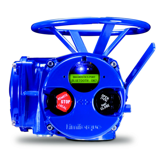
Swanson Flo | 800-288-7926 | www.swansonflo.com Limitorque MX Maintenance and Spare Parts FCD LMENIM2314-00 – 07/08 MX Actuator Subassembly Figure 2.1 – Typical MX Actuator NOTE: MX-05 with B4 base shown flowserve.com... -
Page 12: Mx Actuator Subassembly Components
Swanson Flo | 800-288-7926 | www.swansonflo.com Limitorque MX Maintenance and Spare Parts FCD LMENIM2314-00 – 07/08 2.1 MX Actuator Subassembly Components Table 2.1 – MX Actuator Subassembly Components Description Top-mounted handwheel Drive sleeve Worm shaft Motor Declutch lever Encoder Control panel (CP) Control module Optional bases Thrust base type... -
Page 13: Unit Weights
2. A nameplate with important information is attached to each actuator. Record the following informa- tion for use when you need to contact Limitorque with any questions about your actuator: • Unit type/size • Flowserve Limitorque order number • Serial number Figure 2.2 – MX Nameplate... -
Page 14: Maintenance
Swanson Flo | 800-288-7926 | www.swansonflo.com Limitorque MX Maintenance and Spare Parts FCD LMENIM2314-00 – 07/08 2.3 Maintenance 2.3.1 Recommended Maintenance Under normal operating conditions, the MX is a maintenance-free actuator. Therefore, for normal applications, no formal actuator maintenance is required although visual inspection for oil leakage and excessive noise is recommended every 1 million drive sleeve turns or every 3000 cycles. -
Page 15: Figure 2.3 - Oil Fill/Plug Locations (Mx-05 Through -40)
- consult factory for further information. Table 2.3 – MX-05 and -10 Oil Capacities when using Oil Fill/Plug Ports Nominal Oil Capacities liters MX-05 MX-10 MX-20 Top-mounted handwheel with handwheel up Top-mounted handwheel with terminal compartment up Side-mounted handwheel with terminal compartment up flowserve.com... -
Page 16: O-Ring And Lubrication
Replacement parts are sold in modular subassemblies; therefore, when part replacement is required, order parts at the subassembly levels as shown in this manual. Parts may be ordered from your local Limitorque representative (see www.flowserve.com) or direct from the factory: Telephone: 1-434-528-4400... -
Page 17: Replacement Parts
When parts are identified for warranty or other component replacement, a Return Material Authorization (RMA) must be obtained from Flowserve. Contact factory for a RMA number (see contact information in section 2.5.1). All returned parts must be accompanied by documentation with the following information to obtain credit for returned goods: •... - Page 18 Swanson Flo | 800-288-7926 | www.swansonflo.com Limitorque MX Maintenance and Spare Parts FCD LMENIM2314-00 – 07/08 This page is intentionally blank.
-
Page 19: Remove Actuator From Mounting Adapter
B4 or B4E baseplate, you may leave the B1 base attached to the mounting adapter and remove the actuator only. Or if required, you may remove the bolts that mount type B1 base to mounting adapter. This will allow actuator removal along with optional B1 base. flowserve.com... -
Page 20: Remounting (Type B1/B4/B4E Base)
Swanson Flo | 800-288-7926 | www.swansonflo.com Limitorque MX Maintenance and Spare Parts FCD LMENIM2314-00 – 07/08 STEP 2 WARNING: Potential high-pressure vessel! Before disassembling your actuator, ensure that the valve or other actuated device is isolated and is not under pressure. Lift actuator from mounting adapter. - Page 21 L1, L2, L3, and control wiring in the terminal block. Secure the actuator to the mounting adapter with mounting bolts. STEP 6 Reconnect incoming power leads L1, L2, L3, and control wiring to the terminal block. Restore power source when ready for operation. flowserve.com...
-
Page 22: Actuator Removal With Type A1/A1E Base (Thrust)
Swanson Flo | 800-288-7926 | www.swansonflo.com Limitorque MX Maintenance and Spare Parts FCD LMENIM2314-00 – 07/08 3.2 Actuator Removal with Type A1/A1E Base (Thrust) NOTE: Two procedure options are available for removing the actuator and thrust base: 1. Remove actuator from thrust base, leaving thrust base mounted to mounting flange or removing thrust base separately. -
Page 23: Remounting (Type A1/A1E Base) Actuator Remounting Separate From Thrust Base
STEP 5 Thrust base remounting (if required) Ensure the thrust base stem nut has the two lugs positioned upward to engage with the drive sleeve slots when actuator is reinstalled onto thrust base. Thread thrust base back onto mounting adapter. flowserve.com... - Page 24 Swanson Flo | 800-288-7926 | www.swansonflo.com Limitorque MX Maintenance and Spare Parts FCD LMENIM2314-00 – 07/08 STEP 6 Secure thrust base to mounting adapter with mounting bolts. STEP 7 Actuator remounting Lower the actuator onto the thrust base, making sure thrust nut lugs align and properly engage with drive sleeve slots.
-
Page 25: Removal (Type A1/A1E Base) Actuator And Thrust Base As A Unit
WARNING: Potential high-pressure vessel! Before disassembling your actuator, ensure that the valve or other actuated device is isolated and is not under pressure. Declutch the actuator to manual mode. STEP 3 Rotate the handwheel until the actuator lifts off the threaded stem. flowserve.com... -
Page 26: Remounting (Type A1/A1E Base) Actuator And Thrust Base As A Unit
Swanson Flo | 800-288-7926 | www.swansonflo.com Limitorque MX Maintenance and Spare Parts FCD LMENIM2314-00 – 07/08 3.2.4 Remounting (Type A1/A1E Base) Actuator and Thrust Base as a Unit STEP 4 Actuator and thrust base remounting Declutch the actuator to manual mode. Lift actuator up to the threaded stem and carefully align threads with thrust base threaded stem nut. -
Page 27: Mechanical Assemblies
Figure 4.1 – Motor (MX-05, -10, -20, and -40) 4- 1 4- 2 A ssembly must have rotation of rotor as shown. Phase connections are: 4- 3 T1-Phase 'A ' T2-Phase 'B ' T3-Phase 'C ' 4- 8 Motor leads 4- 4 View A-A 4- 9 flowserve.com... -
Page 28: Removal
Swanson Flo | 800-288-7926 | www.swansonflo.com Limitorque MX Maintenance and Spare Parts FCD LMENIM2314-00 – 07/08 4.1.1 Removal STEP 1 WARNING: Hazardous Voltage! Turn off all power sources to actuator before removing motor assembly. Power sources may include main power or control power. Using an M6 hex key, remove the four M8 screws (#1-14) that mount the motor assembly to the MX-05 through MX-40 actuator. -
Page 29: Remounting
MX-05 through -40 motor wiring will wrap around about 360°. MX-85/140/150 motor wiring will wrap around about 180°. flowserve.com... -
Page 30: Removal And Mounting Of Mx-140 Motor (40 Rpm And Greater)
Swanson Flo | 800-288-7926 | www.swansonflo.com Limitorque MX Maintenance and Spare Parts FCD LMENIM2314-00 – 07/08 STEP 7 Push the rotor shaft onto the protruding worm shaft, aligning the rotor shaft slots with the worm shaft pin. Slide the motor housing spigot/pilot into the actuator housing. -
Page 31: Remounting
4-11 Sheilded ball bearing 4-13 Plate, wiring sheild 4-14 Socket head cap screws 4-15 Socket head cap screws 4-16 Pipe plug 4-17 Plate, motor support 4-18 Shims AS REQ’D 4-19 Socket head cap screws 4-20 Socket head cap screws flowserve.com... -
Page 32: Figure 4.3 - Motor, Support Plate And Adapter (Mx-150)
Swanson Flo | 800-288-7926 | www.swansonflo.com Limitorque MX Maintenance and Spare Parts FCD LMENIM2314-00 – 07/08 Figure 4.3 – Motor, Support Plate and Adapter (MX-150) UNIT HOUSING MOUNT ADAPTER (PC-4-8) TO UNIT HOUSING 1-15 BEFORE MOUNTING MOTOR (PC-4-7) 4-13 4-15 UNIT BASEPLATE 4-18 4-11... -
Page 33: Declutch
Declutch spring Cam spring Declutch latch Latch spring Cam plate Retaining ring 5-10 Socket head cap screw 5-11 O-ring 5-12 Socket head cap screw 5-13 Dowel pin 5-14 Roll pin 5-15 O-ring Figure 4.4 – Declutch (MX-05 and -10) flowserve.com... -
Page 34: Figure 4.5 - Declutch (Mx-20 And -40)
Swanson Flo | 800-288-7926 | www.swansonflo.com Limitorque MX Maintenance and Spare Parts FCD LMENIM2314-00 – 07/08 Table 4.5 – Declutch Parts List (MX-20 and -40) Part Number Description Qty. Declutch cover Declutch shaft Declutch cam Declutch spring Cam spring Declutch latch Latch spring Cam plate Retaining ring... -
Page 35: Removal
NOTE: The MX-20 and -40 declutch assembly may be removed without other subassembly removal, but remounting requires removing the following subassemblies: 1. Handwheel (Subassembly #13) 2. Handwheel adapter (Subassembly #12) 3. Clutch and clutch ring (Subassembly #16) flowserve.com... - Page 36 Swanson Flo | 800-288-7926 | www.swansonflo.com Limitorque MX Maintenance and Spare Parts FCD LMENIM2314-00 – 07/08 STEP 1 WARNING: Potential to operate while dangerous mechanical parts are exposed during subassembly removal. To prevent injury, turn off all power sources to actuator before removing side-mounted and top-mounted handwheel assembly.
-
Page 37: Remounting
1. Handwheel (subassembly #13). (See 5-15 Section 4.3.1.) 2. Handwheel adapter (subassembly #12). (See Section 4.13.1.) 3. Clutch and clutch ring (subassembly #16). (See Section 4.15.1.) Lightly lubricate the O-ring (#5-15) and fit it to the inner race of the declutch cover (#5-1). flowserve.com... - Page 38 Swanson Flo | 800-288-7926 | www.swansonflo.com Limitorque MX Maintenance and Spare Parts FCD LMENIM2314-00 – 07/08 STEP 5 CAUTION: (MX-20 and -40 only) To create proper mating between the cam latch (#5-6) and the shoulder on the worm gear, ensure cam latch is positioned below the worm gear shoulder (see Picture 5a).
- Page 39 Remount the following subassemblies after remounting the declutch assembly. (See corresponding referenced sections for remounting information.) 1. Handwheel (subassembly #13). (See Section 4.3.2.) 2. Handwheel adapter (subassembly #12). (See Section 4.4.2, 4.4.3, and 4.5.3.) 3. Clutch and clutch ring (subassembly #16). (See Section 4.15.2.) flowserve.com...
-
Page 40: Top-Mounted Handwheel (Mx-05, -10, -20, And -40)
Swanson Flo | 800-288-7926 | www.swansonflo.com Limitorque MX Maintenance and Spare Parts FCD LMENIM2314-00 – 07/08 4.3 Top-Mounted Handwheel (MX-05, -10, -20, and -40) Table 4.7 – Top-Mounted Handwheel Parts List (MX-05, -10, -20, and -40) Part Number Description Qty. Handwheel Handwheel Spacer (MX-05 only) 1-10... -
Page 41: Removal
8 mm (MX-20 and -40) hex key, remove the four screws (#1-11) that secure the handwheel (#1-8) to the handwheel adapter assembly (#1-1). 11-1 STEP 2 Lift the handwheel (#1-8) off the handwheel adapter (#1-1). 4.3.2 Remounting STEP 3 Install handwheel (#1-8) onto handwheel adapter assembly (#1-1). flowserve.com... - Page 42 Swanson Flo | 800-288-7926 | www.swansonflo.com Limitorque MX Maintenance and Spare Parts FCD LMENIM2314-00 – 07/08 STEP 4 Align the handwheel slots with the mounting holes. Fit the four screws (#1-11) in handwheel mounting holes and tighten.
-
Page 43: Side-Mounted Handwheel Without Spur Gear Attachment (Mx-10, -20, -85, -140, And -150)
Using force beyond the ratings of the actuator and/or additive forces such as cheater bars, wheel wrenches, pipe wrenches, or other devices on the actuator handwheel or declutch lever may cause serious personal injury and/or damage to the actuator and valve. flowserve.com... -
Page 44: Side-Mounted Handwheel Without Spur Gear Attachment (Mx-85, -140, And -150)
Swanson Flo | 800-288-7926 | www.swansonflo.com Limitorque MX Maintenance and Spare Parts FCD LMENIM2314-00 – 07/08 4.4.1 Side-Mounted Handwheel Without Spur Gear Attachment (MX-85, -140, and -150) Table 4.9 – Side-Mounted Handwheel without Spur Gear Attachment Parts List (MX-85, -140, and -150) Part Number Description Qty. -
Page 45: Removal Of Side-Mounted Handwheel (Mx-10, -20, -85, -140, And -150)
Drain oil from actuator using the lowest of three Oil Plug Drains plugs in your application mounting orientation. NOTE: Oil removal is not necessary if the actuator is mounted on valve or other device with the drive sleeve in a vertical position. flowserve.com... -
Page 46: Limitorque Mx Maintenance And Spare Parts Fcd Lmenim2314-00 - 07/08
Swanson Flo | 800-288-7926 | www.swansonflo.com Limitorque MX Maintenance and Spare Parts FCD LMENIM2314-00 – 07/08 STEP 2 (MX-10 AND -20) CAUTION: Be aware of inner bearing (#13-8) when removing the side-mounted hand- wheel. It may stay in the actuator housing or come out with the side-mounted handwheel assembly. -
Page 47: Remounting
(#13-8). STEP 6 Position the worm shaft cap (#13-2) back on the actuator housing. Using a 6 mm hex key, fit the (#13-9) screws onto the worm shaft cap to secure side-mounted assembly to the actuator housing. flowserve.com... -
Page 48: Side-Mounted Handwheel With Spur Gear Attachment (Mx-40, -85, -140, And -150)
Swanson Flo | 800-288-7926 | www.swansonflo.com Limitorque MX Maintenance and Spare Parts FCD LMENIM2314-00 – 07/08 4.5 Side-Mounted Handwheel With Spur Gear Attachment (MX-40, -85, -140, and -150) Table 4.10 – Side-Mounted Handwheel Parts List (MX-40) WARNING: Do not manu- Part Number Description Qty. -
Page 49: Mx-85, -140, And -150 Handwheel With Sga
Ball bearing 13-24 13-28 Retaining ring Figure 4.11 – Side-Mounted Handwheel With SGA (MX-85, -140, and -150) 13-15 13-23 13-7 13-14 13-10 13-17 13-11 13-2 13-28 13-18 13-13 13-3 13-24 13-22 13-24 13-12 13-17 13-8 13-19 13-9 13-6 13-5 13-1 flowserve.com... -
Page 50: Removal Of Handwheel
Swanson Flo | 800-288-7926 | www.swansonflo.com Limitorque MX Maintenance and Spare Parts FCD LMENIM2314-00 – 07/08 4.5.2 Removal of Handwheel NOTES: The MX-40 handwheel is mounted with a roll pin (#13-7). If removal of the handwheel from the worm shaft is necessary, remove the handwheel and worm shaft assembly from unit before removing roll pin. - Page 51 Remove the four screws (#13-20) from the handwheel spur gear cap (#13-13). 13-20 STEP 3 Remove handwheel spur gear cap assembly. 13-12 Note when assembly is removed, the spur gear (#13-12) is loose in spur gear cap. Remove spur gear. MX-40 13-12 MX-85/140/150 flowserve.com...
- Page 52 Swanson Flo | 800-288-7926 | www.swansonflo.com Limitorque MX Maintenance and Spare Parts FCD LMENIM2314-00 – 07/08 STEP 4 Remove the four M6 screws (#13-9) from the worm shaft plate (#13-2). 13-9 13-2 MX-40 MX-85/140/150 STEP 5 Removing worm shaft assembly. MX-40: Remove adapter plate and worm assembly together (5a).
-
Page 53: Remounting
MX-40 is slip fit in housing (7a). MX-85 is press fit in housing (7b). 13-8 STEP 8 If previously removed, install handwheel worm gear assembly (#12-1). (See Section 4.14.2 for remounting procedure.) Handwheel Worm Gear Adapter (12-1) flowserve.com... - Page 54 Swanson Flo | 800-288-7926 | www.swansonflo.com Limitorque MX Maintenance and Spare Parts FCD LMENIM2314-00 – 07/08 STEP 9 13-2 Ensure O-ring (MX-40) (#13-6) is in place on worm shaft plate. 13-6 MX-40, -85, -140, and -150: Insert worm shaft assembly into actuator housing. Rotate assembly in counterclockwise (CCW) direction to properly mate with handwheel worm gear assembly (#12-1)(9b).
- Page 55 Limitorque MX Maintenance and Spare Parts FCD LMENIM2314-00 – 07/08 STEP 10A AND B - MX-85, -140, AND -150 Ensure gasket (#13-6) is placed on adapter (#13-2) and install adapter to housing and secure with four M8 screws (#13-9). flowserve.com...
- Page 56 Swanson Flo | 800-288-7926 | www.swansonflo.com Limitorque MX Maintenance and Spare Parts FCD LMENIM2314-00 – 07/08 STEP 11 MX-40 (11a) Fit gear (#13-12) onto end of worm shaft 13-1 13-7 (#13-1). Ensure gear slot is fitted into pin (#13-7). MX-85, -140, and -150 (11b and 11c) 13-12 Fit gear (#13-12) onto end of worm shaft.
- Page 57 Check that seal (#13-15), and ball bearings (#13-11, 13-22, and 13-23) are correctly placed in adapter (#13-2) and cap (#13-13). Install handwheel spur cap assembly. Secure with screws (#13-20). Remount handwheel (#13-10) if removed with key (#13-7) and set screw (#13-18). flowserve.com...
-
Page 58: Converting Top-Mounted Handwheel To Side-Mounted Handwheel (Mx-10, -20, And -40)
Swanson Flo | 800-288-7926 | www.swansonflo.com Limitorque MX Maintenance and Spare Parts FCD LMENIM2314-00 – 07/08 4.6 Converting Top-Mounted Handwheel to Side-Mounted Handwheel (MX-10, -20, and -40) 4.6.1 Removing Top-Mounted Handwheel WARNING: Do not manually operate the actuator with devices other than the installed handwheel and declutch lever. -
Page 59: Installing Side-Mounted Handwheel
Install bearing (#13-8) from side-mounted handwheel adapter kit into the actuator housing. MX-10, -20 and -40: the bearing is a slip fit into the housing. 13-8 MX-85, -140, and -150: the bearing is a press fit into the housing. flowserve.com... - Page 60 Swanson Flo | 800-288-7926 | www.swansonflo.com Limitorque MX Maintenance and Spare Parts FCD LMENIM2314-00 – 07/08 STEP 5 Replace the handwheel adapter (#12-5) with the handwheel worm gear (#12-1) that is included in the side-mounted handwheel adapter kit. STEP 6 (MX-20 AND -40 ONLY) Place the O-ring (#12-4) around the handwheel adapter;...
-
Page 61: Thrust Base Type A1/A1E
10-10 not shown 10-11 10-13 10-3 10-13 10-12 10-15 10-2 10-12 10-7 10-16 10-6 CAUTION: The MX-05 through -40 A1/A1E thrust base contains lubrication. Ensure that a quality Lithium-based lubricant is used when reassembling the thrust base. flowserve.com... -
Page 62: Figure 4.13 - Type A1 Thrust Base (Mx-85) - F16 Flange
Swanson Flo | 800-288-7926 | www.swansonflo.com Limitorque MX Maintenance and Spare Parts FCD LMENIM2314-00 – 07/08 Table 4.13 – Type A1 Thrust Base Parts List (MX-85) Part Number Description Qty. 10-1 Thrust base housing 10-2 Thrust base mounting flange 10-3 Thrust nut (A1 or A1E) 10-10 Socket head cap screw... -
Page 63: Figure 4.14 - Type A1 Thrust Base (Mx-85, -140, And -150) - F25 Flange
Thrust Nut 10-10 Socket Head Cap Screws 10-11 Pipe Plug 10-12 Thrust Bearing 10-13 Thrust Washer 10-14 Quad Ring 10-15 O-ring 10-17 Socket Head Cap Screws Figure 4.14 – Type A1 Thrust Base (MX-85, -140, and -150) - F25 Flange flowserve.com... -
Page 64: Removal
Swanson Flo | 800-288-7926 | www.swansonflo.com Limitorque MX Maintenance and Spare Parts FCD LMENIM2314-00 – 07/08 4.7.1 Removal First Remove 1. Remove actuator from mounting adapter. STEP 1 WARNING: Potential to operate while dangerous mechanical parts are exposed during subassembly removal. To prevent injury, turn off all power sources to actuator before removing thrust base assembly. -
Page 65: Torque Base Type B1
O-ring 10-17 Gasket Figure 4.15 – Type B1 Torque Base (MX-05, -10, -20, and -40) 10-8 10-17 (MX-40 only) gasket not shown 10-10 10-14 10-3 10-1 10-11 10-15 10-7 10-6 10-14 (MX-05 & 10) 10-16 (MX-20 & 40) 10-2 flowserve.com... -
Page 66: Removal
Swanson Flo | 800-288-7926 | www.swansonflo.com Limitorque MX Maintenance and Spare Parts FCD LMENIM2314-00 – 07/08 4.8.1 Removal First Remove 1. Remove actuator from mounting adapter. STEP 1 WARNING: Potential to operate while dangerous mechanical parts are exposed during subassembly removal. To prevent injury, turn off all power sources to actuator before removing torque base assembly. -
Page 67: Baseplate Type B4
Table 4.16 – Type B4 Baseplate Parts List Quantity Part Number Description MX-05, -10, -20 MX-85/140/150 and -40 11-1 Baseplate 11-2 Pilot 11-3 Seal Quad ring (85/140/150) 11-4 O-ring 11-5 Socket head cap screw Figure 4.16 – Type B4 Baseplate (MX-05, -10, -20, and -40) flowserve.com... -
Page 68: Removal
Swanson Flo | 800-288-7926 | www.swansonflo.com Limitorque MX Maintenance and Spare Parts FCD LMENIM2314-00 – 07/08 Figure 4.17 – Type B4 Baseplate (MX-85, -140, and -150) 11-3 11-4 11-1 11-5 Stem Nuts (B4, B4E, and BL): Various stem nuts are used with the B4 baseplate: 1. - Page 69 Hold drive sleeve assembly in from opposite end. See Section 4.12.1 and 4.12.2 for optional removal and remounting. Pull the baseplate (#11-1) off the drive sleeve. 11-1 flowserve.com...
-
Page 70: Remounting
Swanson Flo | 800-288-7926 | www.swansonflo.com Limitorque MX Maintenance and Spare Parts FCD LMENIM2314-00 – 07/08 4.9.2 Remounting STEP 3 CAUTION: To ensure actuator is fully secured on mounting plate, ensure baseplate (#11-1) is tightened with the following torque values on mounting screws (#11-5): MX-05 and -10 = 12 ft-lb (16 N m) MX-20 and -40 = 24 ft-lb (32 N m) MX-85, -140, and -150 = 90 ft-lb (114 N m) -
Page 71: Worm Shaft
Part Description MX-05, -10, -20 MX-85, -140, and Number and -40 -150 Worm Worm shaft cap Ball bearing Ball bearing Ball bearing Oil seal O-ring Socket head cap screw Figure 4.18 – Worm Shaft (MX-05, -10, -20, and -40) flowserve.com... -
Page 72: Removal
Swanson Flo | 800-288-7926 | www.swansonflo.com Limitorque MX Maintenance and Spare Parts FCD LMENIM2314-00 – 07/08 4.10.1 Removal First Remove 1. Remove actuator from mounting adapter. 2. Drain oil. 3. Remove motor (subassembly #4). (See Section 4.1.1.) STEP 1 WARNING: Potential to operate while dangerous mechanical parts are exposed during subassembly removal. -
Page 73: Remounting
MX-85, -140, AND -150 ONLY Be sure the motor wiring harness is pushed in, then rotate worm shaft cap (#3-2) around so that tab is holding wiring harness in place. See Section 5.11 for motor wiring harness installation. Motor wiring harness flowserve.com... - Page 74 Swanson Flo | 800-288-7926 | www.swansonflo.com Limitorque MX Maintenance and Spare Parts FCD LMENIM2314-00 – 07/08 STEP 5 Using a hex key, fit the four M6, M8, or M10 screws (#3-9) into the worm shaft cap (#3-2) mounting holes and tighten.
-
Page 75: Drive Sleeve (Mx-05 And -10)
Table 4.18 – Drive Sleeve Parts List (MX-05 and -10) Part Number Description Qty. Drive sleeve Worm gear Encoder drive gear Ball bearing Retaining ring Drive sleeve key Clutch Clutch spring Retaining ring Figure 4.19 – Drive Sleeve (MX-05 and -10) flowserve.com... -
Page 76: Removal
Swanson Flo | 800-288-7926 | www.swansonflo.com Limitorque MX Maintenance and Spare Parts FCD LMENIM2314-00 – 07/08 4.11.1 Removal First Remove 1. Remove actuator from mounting adapter. 2. Drain oil. 3. Remove thrust base (subassembly #10) - if fitted. 4. Remove motor (subassembly #4). (See Section 4.1.1.) 5. -
Page 77: Remounting
Remount all removed subassemblies according to their remounting instructions in the following order: 1. Base plate (subassembly #11). (See Section 4.9.2.) 2. Worm shaft (subassembly #3). (See Section 4.10.2.) 3. Motor (subassembly #4). (See Section 4.1.2.) 4. Thrust base (subassembly #10) - if fitted. (See Section 4.7.2.) flowserve.com... -
Page 78: Drive Sleeve (Mx-20, -40, -85, -140, And -150)
Swanson Flo | 800-288-7926 | www.swansonflo.com Limitorque MX Maintenance and Spare Parts FCD LMENIM2314-00 – 07/08 4.12 Drive Sleeve (MX-20, -40, -85, -140, and -150) Table 4.19 – Drive Sleeve Parts List (MX-20, -40, -85, -140, and -150) Quantity MX-85, -140, and Part Description -150... -
Page 79: Removal
7. Remove handwheel adapter (subassembly #12). (See Section 4.14.1.) 8. Remove clutch and clutch ring (subassembly #16). (See Section 4.15.1.) 9. Remove handwheel declutch (subassembly #5). (See Section 4.2.1.) 10. Remove base plate (subassembly #11). (See Section 4.9.1 or Section 4.12.1 for MX-85, -140, and -150) flowserve.com... - Page 80 Swanson Flo | 800-288-7926 | www.swansonflo.com Limitorque MX Maintenance and Spare Parts FCD LMENIM2314-00 – 07/08 WARNING: (MX-85, -140, and -150) The drive sleeve assembly may slip and fall out of housing when removing baseplate assembly. Hold the drive sleeve assembly in from opposite end when removing baseplate assembly.
-
Page 81: Remounting
If the bearing is a tight fit, gently tap the bottom of the drive sleeve (#2-1) with a mallet to properly seat. MX-85, -140, and -150: See Section 4.12.4 for optional remounting of drive sleeve and baseplate. flowserve.com... -
Page 82: Mx-85, -140, And -150 Optional Drive Sleeve And Baseplate Removal
Swanson Flo | 800-288-7926 | www.swansonflo.com Limitorque MX Maintenance and Spare Parts FCD LMENIM2314-00 – 07/08 4.12.3 MX-85, -140, and -150 Optional Drive Sleeve and Baseplate Removal First Remove 1. Remove actuator from mounting adapter. 2. Drain oil. 3. Remove thrust base (subassembly #10) - if fitted. (See Section 4.8.1.) 4. - Page 83 (lugs of drive sleeve up) and set down on table. NOTE: The drive sleeve assembly is not held together and will fall apart if set down on a lug end of drive sleeve. Lugs flowserve.com...
-
Page 84: Mx-85, -140, And -150 Optional Drive Sleeve And Baseplate Remounting
Swanson Flo | 800-288-7926 | www.swansonflo.com Limitorque MX Maintenance and Spare Parts FCD LMENIM2314-00 – 07/08 4.12.4 MX-85, -140, and -150 Optional Drive Sleeve and Baseplate Remounting STEP 1 Assemble drive sleeve assembly with drive sleeve lying on opposite end of lugs. Place worm gear (#2-2), key (#2-6) and encoder drive gear (#2-3) onto the drive sleeve (#2-1). -
Page 85: Handwheel Adapter (Mx-05)
Limitorque MX Maintenance and Spare Parts FCD LMENIM2314-00 – 07/08 4.13 Handwheel Adapter (MX-05) Table 4.20 – Handwheel Adapter Parts List (MX-05) Part Number Description Qty. 12-1 Handwheel adapter 12-2 Needle bearing 12-3 Quad ring 12-4 O-ring Figure 4.22 – Handwheel Adapter (MX-05) Figure 4.23 – Handwheel (MX-05) flowserve.com... -
Page 86: Removal
Swanson Flo | 800-288-7926 | www.swansonflo.com Limitorque MX Maintenance and Spare Parts FCD LMENIM2314-00 – 07/08 4.13.1 Removal First Remove 1. Remove actuator from mounting adapter. 2. Drain oil. 3. Remove top-mounted handwheel (#1-8). (See Section 4.3.1.) 4. Remove motor (subassembly #4). (See Section 4.1.1.) 5. -
Page 87: Remounting
Handwheel Adapter Screw Taps STEP 5 Once handwheel adapter assembly is installed in actuator housing, wind wave spring (#1-10) into groove on the handwheel adapter. 1-10 flowserve.com... - Page 88 Swanson Flo | 800-288-7926 | www.swansonflo.com Limitorque MX Maintenance and Spare Parts FCD LMENIM2314-00 – 07/08 STEP 6 Slide handwheel spacer (#1-9) over handwheel adapter assembly, ensuring wave spring (#1-10) is seated in groove of the handwheel spacer. 1-10 STEP 7 Remount all removed subassemblies according to the remounting instructions in the following order: 1.
-
Page 89: Handwheel Adapter (Mx-10, -20 And -40)/Handwheel Worm Gear (Mx-10, -20, -40, -85, -140, And -150)
Handwheel Worm Gear (MX-10, -20, -40, -85, -140, and -150) Table 4.21 – Handwheel Adapter Assembly Parts List Part Number Description Qty. 12-1 Handwheel adapter 12-2 Ball bearing 12-3 Quad ring 12-4 O-ring Figure 4.24 – Handwheel Adapter Assembly flowserve.com... -
Page 90: Figure 4.25 - Handwheel Worm Gear Assembly
Swanson Flo | 800-288-7926 | www.swansonflo.com Limitorque MX Maintenance and Spare Parts FCD LMENIM2314-00 – 07/08 Table 4.22 – Handwheel Worm Gear Assembly Parts List Part Number Description Qty. 12-1 Handwheel worm gear 12-2 Ball bearing 12-3 Quad ring 12-4 O-ring 12-5 Handwheel adapter... -
Page 91: Removal
WARNING: Potential to operate while dangerous mechanical parts are exposed during subassembly removal. To prevent injury, turn off all power sources to actuator before removing handwheel adapter assembly. Power sources may include main power or control power. Remove the four screws (#1-33) from the 1-33 retainer plate (#1-32). 1-32 flowserve.com... -
Page 92: Remounting
Swanson Flo | 800-288-7926 | www.swansonflo.com Limitorque MX Maintenance and Spare Parts FCD LMENIM2314-00 – 07/08 STEP 2 Lift off the retainer plate (#1-32). STEP 3 Pull the handwheel adapter assembly (#12) out of the actuator housing. STEP 4 (MX-10 ONLY) Lift out wave spring (#1-10) from the actuator housing. - Page 93 STEP 7 (MX-20 AND -40 ONLY) Place the O-ring (#12-4) around handwheel adapter, pressing the O-ring into the slot between the handwheel adapter assembly (#12) and the actuator housing (approximately every 15° to 30°) until the O-ring seats into slot. 12-4 flowserve.com...
- Page 94 Swanson Flo | 800-288-7926 | www.swansonflo.com Limitorque MX Maintenance and Spare Parts FCD LMENIM2314-00 – 07/08 STEP 8 NOTE: Retainer plate (#1-32) may sit slightly above actuator housing until screws are retightened. WARNING: The MX-10 through -150 require precaution to prevent damage to the declutch latch.
-
Page 95: Clutch And Clutch Ring Components (Mx-20, -40, -85, -140, And -150)
Table 4.23 – Clutch and Clutch Ring Components Parts List Part Number Description Qty. 1-38 Clutch 1-37 Clutch ring 1-39 Clutch spring 1-40 Spring spacer Figure 4.26 – MX-20 and -40 Clutch Figure 4.27 – MX-85, -140, and -150 Clutch and Ring Components and Ring Components flowserve.com... -
Page 96: Removal
Swanson Flo | 800-288-7926 | www.swansonflo.com Limitorque MX Maintenance and Spare Parts FCD LMENIM2314-00 – 07/08 4.15.1 Removal First Remove 1. Drain oil. 2. Remove top-mounted handwheel (#1-8) or side-mounted handwheel (subassembly #13). (See Section 4.3.1, Section 4.4.2, or Section 4.5.2.) 3. -
Page 97: Remounting
Fit the clutch ring (#1-37) over the drive sleeve with the tangs (forked protrusion) facing down. Seat tangs over declutch cam (see pictures 5a Clutch and 5a1 at right). See warning note in Section Tangs on Clutch 4.14.2, Step 8. Ring (1-37) Tangs Declutch Cam flowserve.com... -
Page 98: Figure 4.28 - Mx-85, -140, And -150 Clutch Ring
Swanson Flo | 800-288-7926 | www.swansonflo.com Limitorque MX Maintenance and Spare Parts FCD LMENIM2314-00 – 07/08 Table 4.24 – Clutch Ring Assembly Parts List Part Number Description Qty. 15-1 Clutch ring 15-2 Roller 15-3 Roll pin 15-4 Spacer 15-5 Latch spring 15-6 Roll pin 15-7... - Page 99 Note in Section 4.14.2, Step 8. Housing Hole for Clutch Ring Screw for Anti- Rotation of Clutch Ring Assembly STEP 6 Slide clutch (#1-38) over drive sleeve assembly. 1-38 STEP 7 1-39 Slide spring (#1-39) over drive sleeve assembly. flowserve.com...
- Page 100 Swanson Flo | 800-288-7926 | www.swansonflo.com Limitorque MX Maintenance and Spare Parts FCD LMENIM2314-00 – 07/08 STEP 8 Slide spring spacer (#1-40) over drive sleeve assembly. 1-40 STEP 9 Remount removed subassemblies according to their remounting instructions in the following order: 1.
-
Page 101: Electronic Assemblies
Torsion spring 7-25 7-14 Red knob cap 7-19 7-19 O-ring retainer 7-21 O-ring 7-21 7-23 Controls cover 8-24 7-24 Window 7-25 Snap ring 7-27 Socket head cap screw 8-24 PC board 7-24 8-25 Pan head machine screw (M4x6) 7-23 flowserve.com... -
Page 102: Control Module
Swanson Flo | 800-288-7926 | www.swansonflo.com Limitorque MX Maintenance and Spare Parts FCD LMENIM2314-00 – 07/08 5.2 Control Module (Units Supplied Before September 2003) Table 5.2 – Control Module Parts List Part Number Description Qty. Controls chassis plate Power board Main processor board Phillips pan head mach Socket head cap screw (M4x10) -
Page 103: Removal
If the I/O option board is installed, disconnect wire harness plug P3 and P4. STEP 2 If DDC board is installed, disconnect wire harness plug P2. STEP 3 Disconnect wire harness plug P1 and P4 from the main processor board. flowserve.com... - Page 104 Swanson Flo | 800-288-7926 | www.swansonflo.com Limitorque MX Maintenance and Spare Parts FCD LMENIM2314-00 – 07/08 STEP 4 Disconnect wire harness plugs P1 and P2 from the main power board. STEP 5 Using a 3 mm hex key, loosen the three M4 mounting plate screws (#8-7) located at the back of the controls compartment.
- Page 105 (#8-25) that retain the CP board inside the CP cover. STEP 9 Lift the CP board out of the CP cover. (See Section 5.2.3 for fuse replacement.) (See Section 5.2.4 for control module return options.) (See Section 5.2.5 for EPROM care and replacement.) flowserve.com...
-
Page 106: Remounting
Swanson Flo | 800-288-7926 | www.swansonflo.com Limitorque MX Maintenance and Spare Parts FCD LMENIM2314-00 – 07/08 5.2.2 Remounting If the standard board set was separated from the DDC and/or I/O option boards, reassemble boards back together as a complete unit before remounting the control module back into the actuator. STEP 10 WARNING: Hazardous Voltage! Turn off all power sources to actuator before remounting ACP assembly. - Page 107 P2 on ® main power board. STEP 13 Connect the AMP power connector to the fuse ® section on the main power board. Plug STEP 14 Connect the 20-pin Molex harness to plug P1 ® on the main processor board. flowserve.com...
- Page 108 Swanson Flo | 800-288-7926 | www.swansonflo.com Limitorque MX Maintenance and Spare Parts FCD LMENIM2314-00 – 07/08 STEP 15 Connect the 4-pin Molex harness to plug P4 ® on the main processor board. STEP 16 If DDC board is installed, connect 10-pin Molex harness to plug P2 on DDC board ®...
-
Page 109: Fuse Replacement
(#8-8) may be necessary to access the secondary fuse. The view to the right shows the control module with the chassis assembly removed. Figure 5.3 – Location of Fuses and Voltage Jumper Primary Secondary Fuses Fuse Voltage Jumper flowserve.com... -
Page 110: Control Module Return Options
Swanson Flo | 800-288-7926 | www.swansonflo.com Limitorque MX Maintenance and Spare Parts FCD LMENIM2314-00 – 07/08 5.2.4 Control Module Return Options Please contact factory for return options. 5.2.5 EPROM Care and Replacement There are four EPROMs in the through hole fabricated MX Control Module. These are located on the LCS board, on the main processor board, on the Power Board, and on the DDC option board. -
Page 111: Figure 5.6 - Power Board
Figure 5.6 – Power Board NOTE: Power board EPROM is not included in replacement kit. This EPROM should not be replaced in the field. Figure 5.7 shows the location of the DDC EPROM on the DDC Option Board. Figure 5.7 – DDC Board flowserve.com... - Page 112 5.2.5.3 EPROM Installation It is recommended that an IC insertion/extraction tool be used to hold the EPROM for installation. Flowserve Limitorque provides a kit which contains an EPROM removal tool; P/N 102424. To insert a replacement EPROM, use the following procedure: The notch at one end of the EPROM must be lined up with the notch at one end of the socket.
-
Page 113: Installation And Removal Of Smt Controls
Before handling electronic components, ensure that you are discharged of static electricity by briefly touching a grounded metal object. Flowserve recommends the use of a wrist strap grounded to an appropriate ground. STEP 2 Attach the SMT terminal block conversion wiring harness (P/N 64-825-0010-4) to the existing through hole wiring harness. - Page 114 Swanson Flo | 800-288-7926 | www.swansonflo.com Limitorque MX Maintenance and Spare Parts FCD LMENIM2314-00 – 07/08 STEP 5 Position the power assembly over the three mounting screw heads (#1-45). Rotate the subassembly in the clockwise (CW) direction until all three screws are seated in the key slots.
- Page 115 STEP 13 CAUTION: Potential to pinch cables. When remounting CP cover, take special care not to pinch the ribbon cables. Dress the cables as shown, being careful to position wires so that they pass perpendicularly over the housing flange. flowserve.com...
-
Page 116: Removal
Swanson Flo | 800-288-7926 | www.swansonflo.com Limitorque MX Maintenance and Spare Parts FCD LMENIM2314-00 – 07/08 STEP 14 NOTE: The face of the CP may be installed in any one of four 90° incremental positions. When changing CP position, avoid over-twisting the ribbon cable. Rotate the CP until the display orientation of the front face is correct for normal viewing, and then slide the CP assembly into the actuator... -
Page 117: (Some Units Supplied From December 2006 With Majority After September 2007)
220Vac 60Hz (226) 230Vac 50/60Hz |226| 240Vac 60Hz |226| 380Vac 50/60Hz |366| 400Vac 50Hz |392| 415Vac 50Hz |392| 440Vac 50/60Hz |450| 460Vac 60Hz |450| 480Vac 60Hz |450| 525Vac 50/60Hz [505] 550Vac 60Hz [530] 575Vac 60Hz [572] 600Vac 60Hz [572] flowserve.com... -
Page 118: Removal
CAUTION: Potential to cause electrostatic damage to electronic components. Before handling electronic components, ensure that you are discharged of static electricity by briefly touching a grounded metal object. Flowserve recommends the use of a wrist strap grounded to an appropriate ground. -
Page 119: Mounting Of Standard And Optional Controls With 54-Point Terminal Block And Four Led Configuration
Ensure that the jumper on DigOut board 1 is in the 1-2 position and the jumper on DigOut board 2 is in the 3-4 position. Connect the 12-22 pin adapter to Cable J1 (12-pin), then connect it to socket J3 (22-pin) of board 1. Connect cable J5 to socket J3 of board 2. flowserve.com... -
Page 120: Table 5.4 - Control Board Connectors
Swanson Flo | 800-288-7926 | www.swansonflo.com Limitorque MX Maintenance and Spare Parts FCD LMENIM2314-00 – 07/08 STEP 5 – ANALOG OPTION BOARD CONNECTION Connect to the control cover using four (4) M4x25 pan head screws if one analog board is installed. Connect to the control cover using four (4) M4x40 pan head screws if two analog boards are installed. -
Page 121: Figure 5.10 - Option Board Assembly
NOTE: The face of the ACP may be installed in any one of four 90° incremental positions. When changing ACP position, avoid over-twisting the ribbon cable(s). Rotate the ACP until the display orientation of the front face is correct for normal viewing, and then slide the ACP assembly into the actuator housing. flowserve.com... -
Page 122: Removal
Swanson Flo | 800-288-7926 | www.swansonflo.com Limitorque MX Maintenance and Spare Parts FCD LMENIM2314-00 – 07/08 5.5.2 Removal For removal, follow installation instructions in reverse. 5.6 Adding Electronic Options to Your MX Actuator (Most Supplied After September 2007) Listed below are the options available for the MX. 1. -
Page 123: Restoring Power To Actuator With New Control Module
Qty. 1-20 O-ring 1-21 Retaining ring 1-43 Pan head (M3x4) plastic screw 8-15 Terminal block 8-16 Self-lock combo head screw (M3x5) 8-17 Self-lock combo head screw (M5x8) 8-18 Cover plate 8-19 Pan head self-tapping screw 8-20 Control wiring harness flowserve.com... -
Page 124: Removal
Swanson Flo | 800-288-7926 | www.swansonflo.com Limitorque MX Maintenance and Spare Parts FCD LMENIM2314-00 – 07/08 Figure 5.12 – Terminal Block 5.8.1 Removal CAUTION: Potential to cause electrostatic damage to electronic components. Before handling electronic components, ensure that you are discharged of static electricity by briefly touching a grounded metal object. - Page 125 STEP 4 Remove terminal block assembly. Terminal Block Assembly STEP 5 Disconnect leads L1, L2, and L3 from back of terminal block. flowserve.com...
-
Page 126: Remounting
Swanson Flo | 800-288-7926 | www.swansonflo.com Limitorque MX Maintenance and Spare Parts FCD LMENIM2314-00 – 07/08 STEP 6 Feed the terminal block harness plugs over the contactor assembly (in the control module compartment) while removing the terminal 1-20 block from the terminal block compartment. NOTE: An O-ring (#1-20) is included with the terminal block assembly. - Page 127 Connect the incoming power leads and the control wiring according to the application wiring diagram if the terminal block has been replaced. Install the terminal compartment cover and secure with four M8 screws using a 6 mm hex key. flowserve.com...
-
Page 128: Mx Terminal Block (Supplied With Most Actuators Since March 2007)
Swanson Flo | 800-288-7926 | www.swansonflo.com Limitorque MX Maintenance and Spare Parts FCD LMENIM2314-00 – 07/08 5.9 MX Terminal Block (Supplied With Most Actuators Since March 2007) Table 5.7 – Terminal Block Parts List Part Number Description Qty. 1-20 O-ring 1-21 Retaining ring 8-15... -
Page 129: Control Module-Contactor Assembly
Table 5.8 – Control Module-Contactor Assembly Parts List Part Number Description Qty. 8-27 Contactor bracket 8-28 Socket head cap screw (M4x8) 8-29 Contactor assembly Figure 5.15 – Control Module - Contactor Assembly and Wiring Diagrams flowserve.com... -
Page 130: Removal
Swanson Flo | 800-288-7926 | www.swansonflo.com Limitorque MX Maintenance and Spare Parts FCD LMENIM2314-00 – 07/08 Figure 5.15 – (continued) 5.10.1 Removal First Remove 1. Remove motor (subassembly #4). (See Section 4.1.1.) 2. Remove control panel (subassembly #7). (See Section 5.1.) 3. -
Page 131: Remounting
NOTE: Only the MX-05, -10, -20 and -40 have the long motor power socket lead. MX-85, -140, AND -150 Motor Power Plug Disconnect connectors 4 and 5 to motor lead harness. 5.10.2 Remounting STEP 4 Insert contactor assembly into control module cavity. flowserve.com... - Page 132 Swanson Flo | 800-288-7926 | www.swansonflo.com Limitorque MX Maintenance and Spare Parts FCD LMENIM2314-00 – 07/08 STEP 5 Route leads L1, L2, and L3 (input power) to the terminal block cavity. Motor Power Plug MX-05, -10, -20 AND -40 ONLY Motor Cavity Feed the motor power plug through the Terminal Block...
-
Page 133: Replacing 19 Amp Reverser On The Mx-140 And -150 (Not For Most Actuators Shipped After September 2007)
Follow the steps in 5.10.1. Remove control cover and disconnect the encoder and controls package. Remove controls package from MX housing. STEP 2 Remove terminal cover, retaining ring, terminal block and O-ring to access the back of the terminal block. flowserve.com... - Page 134 Swanson Flo | 800-288-7926 | www.swansonflo.com Limitorque MX Maintenance and Spare Parts FCD LMENIM2314-00 – 07/08 STEP 3 Disconnect black, blue and brown wires (L1, L2 and L3) from back of terminal block. STEP 4 Disconnect the lead seal from the reverser by unplugging the 2-pin and single-pin white connectors. STEP 5 Disconnect and remove the encoder mounting screws and the encoder.
- Page 135 Connect the black 6-pin connector from the reverser to the Power board. STEP 15 Connect the encoder ribbon to the PC board in the control cover. STEP 16 Reconnect the cables disconnected during step 1. NOTE: The black 2-pin connector is not used with this reverser. flowserve.com...
-
Page 136: Amp Power Assembly For Units Shipped After September 2007
Swanson Flo | 800-288-7926 | www.swansonflo.com Limitorque MX Maintenance and Spare Parts FCD LMENIM2314-00 – 07/08 STEP 17 Install the control cover and the mounting screws. STEP 18 Complete by following Step 9 in Section 5.10. 5.12 19 Amp Power Assembly for Units Shipped After September 2007 Table 5.9 –... -
Page 137: Encoder (Through Hole And Surface Mount Technology, Most Units Prior To September 2007)
September 2007) Table 5.10 – Encoder Parts List Part Number Description Qty. Encoder assembly 1-36 Socket head cap screw (M4x16) 6-11 Input gear, 78-tooth (ID 3 through 8) 6-24 Input gear, 69-tooth (ID 1 or 2) flowserve.com... -
Page 138: Removal
Swanson Flo | 800-288-7926 | www.swansonflo.com Limitorque MX Maintenance and Spare Parts FCD LMENIM2314-00 – 07/08 Figure 5.16 – Encoder Table 5.11 – Encoder Drive Sleeve Speed (RPM) Drive Sleeve Speed ID 50 Hz 84/110 127/143 60 Hz 100/131 155/170 1: MX-85, -140, and -150 only. - Page 139 Picture 1b to locate screws (#1-36); note important cautionary statement discussed with Step 1 and 1a). 1-36 1-36 14-8 1-36 STEP 2 Pull the complete encoder straight out of the mounting holes to disengage the gear drive from the encoder drive cartridge pinion. flowserve.com...
-
Page 140: Remounting
Swanson Flo | 800-288-7926 | www.swansonflo.com Limitorque MX Maintenance and Spare Parts FCD LMENIM2314-00 – 07/08 5.13.2 Remounting STEP 3 WARNING: Hazardous Voltage! Turn off all power sources to actuator before remounting encoder assembly. Power sources may include main power. If the actuator uses drive sleeve speed ID 1 or 2, ensure the optional encoder input gear (#6-24) is installed on the encoder. -
Page 141: Encoder Drive Cartridge (Most Units Prior To September 2007)
NOTE: Reference the Output RPM block located on the MX nameplate and cross-reference in table above to determine the unit Drive Speed ID. NOTE 1: MX-85, -140, and -150 only. NOTE 2: N/A MX-85, -140, and -150. Figure 5.17 – Encoder Drive Cartridge 14-8 14-2 14-1 14-7 14-4 14-5 14-9 14-4 14-3 flowserve.com... -
Page 142: Removal
Swanson Flo | 800-288-7926 | www.swansonflo.com Limitorque MX Maintenance and Spare Parts FCD LMENIM2314-00 – 07/08 5.14.1 Removal NOTE: Before removal you must: 1. Drain oil. 2. Remove the CP cover (subassembly #7). (See Section 5.1.) 3. Remove the control module (subassembly #8). (See Section 5.2.1.) 4. -
Page 143: Remounting
(#6-25) is installed on the encoder. Fit the encoder drive cartridge into the actuator housing. STEP 4 Using a 3 mm hex key, fit the M4 screw (#14-8) into the actuator housing to secure the encoder cartridge. flowserve.com... -
Page 144: Removal And Replacement Of Mx Encoder (Supplied With Most Actuators Since September 2007)
Swanson Flo | 800-288-7926 | www.swansonflo.com Limitorque MX Maintenance and Spare Parts FCD LMENIM2314-00 – 07/08 5.15 Removal and Replacement of MX Encoder (Supplied With Most Actuators Since September 2007) Table 5.14 – Encoder Parts List Part Number Description Qty. Encoder assembly 1-36 Socket head cap screw (M4x10) -
Page 145: Removal
If needed to align gearing, declutch the actuator and turn handwheel until the encoder gear engages with the drive cartridge pinion). Fit the three M4 screws (#1-36) and tighten using a 3 mm hex key. Do not overtighten. flowserve.com... -
Page 146: Encoder Drive Cartridge (Supplied With Most Actuators Since September 2007)
Swanson Flo | 800-288-7926 | www.swansonflo.com Limitorque MX Maintenance and Spare Parts FCD LMENIM2314-00 – 07/08 5.16 Encoder Drive Cartridge (Supplied With Most Actuators Since September 2007) Table 5.16 – Encoder Drive Cartridge Parts List Part Number Description Qty. 14-1 Encoder drive cartridge 14-2 Encoder drive shaft... -
Page 147: Removal
WARNING: Hazardous Voltage! Turn off all power sources to actuator before removing encoder drive cartridge. Power sources may include main power or control power. Remove the M4 screw (#14-8) using a 3 mm hex key. 14-8 STEP 2 Withdraw the complete encoder drive cartridge from the actuator housing. flowserve.com... -
Page 148: Remounting
Swanson Flo | 800-288-7926 | www.swansonflo.com Limitorque MX Maintenance and Spare Parts FCD LMENIM2314-00 – 07/08 5.16.2 Remounting STEP 3 If actuator uses drive sleeve speed ID 1 or 2, ensure the input gear (#6-25) is installed on the encoder. Fit the encoder drive cartridge into the actuator housing. -
Page 149: Motor Lead Harness (Mx-85, -140, And -150)
STEP 1 If the worm shaft assembly (subassembly #3) is still mounted in the unit, remove the four screws (#3-9) and rotate the cap (CCW) to rotate the cap tab away from the motor lead seal. Motor Lead Seal flowserve.com... -
Page 150: Remounting
Swanson Flo | 800-288-7926 | www.swansonflo.com Limitorque MX Maintenance and Spare Parts FCD LMENIM2314-00 – 07/08 STEP 2 Remove the motor lead harness by threading the harness back through the housing and out the motor end. Work the three connectors out through the hole/slot in the housing one at a time. -
Page 151: Solid State Motor Reverser Upgrade Instructions (Most Units Prior To September 2007)
Socket head cap screws (CP) 1-52 Solid state reverser assembly 1-53 SSMR protection fuse assembly 1-54 Motor fuse block assembly 1-55 Standoff 1-56 Washer Figure 5.21 – Cutaway View of SSMR Controls Area 1-53 1-56 1-52 1-18 8-28 7-27 1-19 1-55 flowserve.com... -
Page 152: Disassembly Procedure
Swanson Flo | 800-288-7926 | www.swansonflo.com Limitorque MX Maintenance and Spare Parts FCD LMENIM2314-00 – 07/08 Tools required: • M3 hex key • M6 hex key • Phillips head screwdriver • Flat head screwdriver 5.18.1 Disassembly Procedure Figure 5.22 – Disassembly Procedure 7-44 1-18 8-24... -
Page 153: Assembly Procedure
Motor fuse NOTE: The Ferraz-Shawut replacement part numbers for the fuses that are supplied for L3 are listed in the third column in Table 5.19. These fuses can be ordered from Flowserve Limitorque using the part number in the second column. -
Page 154: Figure 5.24 - Control Module Reinstallation
Swanson Flo | 800-288-7926 | www.swansonflo.com Limitorque MX Maintenance and Spare Parts FCD LMENIM2314-00 – 07/08 STEP 3 Route the terminal block plug bundle over the top of the reverser assembly and mount the terminal block per Section 5.8.2, Steps 7 through 10. STEP 4 Mount the solid state reverser assembly (1-52) in the unit housing using the existing M4 contactor mounting screws (8-28). -
Page 155: Mounting Of Ssmr (Solid State Motor Reverser) In Units Shipped After February 2008
5.19 Mounting of SSMR (Solid State Motor Reverser) in units shipped after February 2008 Table 5.19 - SSMR Parts List Part Number Description Qty. 1-18 Controls cover assembly 7-27 Socket head cap screws 1-52 Solid state reverser power assembly 1-55 Standoff flowserve.com... -
Page 156: Figure 5.25 - Ssmr (Solid State Motor Reverser)
CAUTION: Potential to cause electrostatic damage to electronic components. Before handling elec- tronic components, ensure that you are discharged of static electricity by briefly touching a grounded metal object. Flowserve recommends the use of a wrist strap grounded to an appropriate ground. STEP 1 Install the three (3) standoffs (#1-55) into the control board housing mounting holes. -
Page 157: Complete Conversion To Smt Controls
Follow the steps as listed in Section 5.8.1 for removal of the existing through hole terminal block. To replace with new SMT ready terminal block (P/N 26100-006) follow steps as listed in Section 5.8.2. Follow steps as listed in Section 5.10 for removal of the existing contactor assembly. flowserve.com... -
Page 158: Spare And Replacement Parts
Complete actuator seal kits are available for the MX-05/10, the MX-20/40 and the MX-85/140/150. Flowserve recommends stock levels for seal kits of 10% of the total population of each actuator model and size. Also, an adequate supply of Flowserve approved oil (Mobil... -
Page 159: Critical Components
The following parts are not subject to wear but are still recommended for stock due to their critical nature. Flowserve recommends stock levels of between 5% and 10% of the total population of each part with a minimum of one of each in order to support the product for life. -
Page 160: Severe Duty
6. Stall/overload condition Flowserve strongly recommends using OEM parts to support and maintain your MX actuator. Installing parts other than genuine Flowserve Limitorque parts could cause premature failure of your actuator and voids any remaining warranty. The above guidelines are provided to assist you in determining your unique spare parts needs. Please contact your local Limitorque Sales Office or local Authorized Stocking Distributor for additional help in evaluating your needs. - Page 161 Swanson Flo | 800-288-7926 | www.swansonflo.com Limitorque MX Maintenance and Spare Parts FCD LMENIM2314-00 – 07/08 This page is intentionally blank. flowserve.com...
-
Page 162: Regulatory Information
Non-Electrical Equipment for Potentially Explosive Atmospheres Manager, Product Management EN 13463-1:2001 (Title) Manufacturer’s Name Flowserve Limitorque Limitorque, a division of Flowserve Corporation 5114 Woodall Rd., Lynchburg VA 24502 (Place) Manufacturer’s Address 5114 Woodall Road December 9, 2005 Lynchburg, VA 24502 (Date) Importer’s Name... - Page 163 Swanson Flo | 800-288-7926 | www.swansonflo.com...
- Page 164 Flowserve Corporation has established industry leadership in the design and manufacture of its products. When properly selected, this Flowserve product is designed to perform its intended China function safely during its useful life. However, the purchaser or user of Flowserve products should be aware that Flowserve products might be used in numerous applications under a wide Limitorque Beijing, Pte., Ltd.
Need help?
Do you have a question about the Limitorque MX-40 and is the answer not in the manual?
Questions and answers