
Related Manuals for Flowserve NORBRO 40R Series


Summary of Contents for Flowserve NORBRO 40R Series
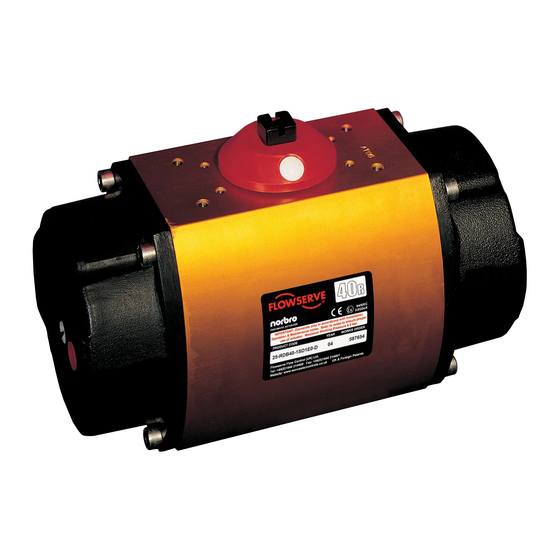
- Page 1 USER INSTRUCTIONS Installation NORBRO Series 40R Pneumatic Actuator Operation Maintenance FCD NBENIM0002-03-A4 07/15...
-
Page 2: Table Of Contents
Never use an actuator on a duty, which exceeds to avoid mistakes, which, in themselves, might its prescribed operating parameters. Refer to directly or indirectly cause severe personal injury Flowserve Flow Control Technical Sales for or property damage. further information. Never modify or alter actuators unless the manufacturer has been consulted and/or recommends such changes. -
Page 3: Description
Flowserve suggests a cover be used, tioner, connections etc. or mount the actuator such that the solenoid 2.16 Care must be taken when removing the actu- block is upside down. -
Page 4: Actuator Markings
Maximum Working Pressure see below. PRODUCT CODE YEAR WORKS ORDER Works Order Number Year of Manufacture Flowserve Flow Control (UK) Ltd. Tel: +44(0)1444 314400 Fax: +44(0)1444 314401 Flowserve Flow Control (UK) Ltd Website: www.flowserve.com UK & Foreign Patents Product Code... - Page 5 but with Clockwise to close Size 40R, if furnished with factory sole- FOR“FAIL-OPEN” NOTE: operation, the pistons in the actuator will noid, shall be “cross-line” mounted (i.e. at 90 need to be removed and reasembled from degrees to the pipe run) to ensure adequate the opposite ends of the actuator (keeping clearance for air connections.
-
Page 6: Fitting Indicators
FITTING INDICATORS Actuator sizes 10, 15, 20 White Plugs Red Plugs White Plugs Red Plugs White Plugs Red Plugs White Plugs Red Plugs Fig.: 1 Fig.: 2 As supplied Alternative Indicating Position AIR SUPPLY AND INSTALLATION NOTE: Indicator is set up to show pistons together on actuator, i.e. -
Page 7: Air Consumption
Recommended Tubing Sizes: 3° overtravel at each end of travel (limit stop version). Rotation is accomplished by feeding In order to provide sufficient flow of supply supply air into the center chamber, forcing air to the Series 40R actuator, the following the two opposing pistons apart, resulting in tubing sizes are recommended: a counter-clockwise rotation of the drive shaft... -
Page 8: Actuator With Solenoid
and the lock nut retightened. For size 10 to 10.3 Standard Stroke Times 35 turn screw clockwise to decrease rotation Standard stroke times of the Series 40R actu- and counterclockwise to increase rotation. For ator are shown in the following table. Times size 40 to 50 the reverse applies. -
Page 9: Maintenance
13.2.1 Turn on signal voltage. Check solenoid for actuators is a Rocol Sapphire Lo-Temp 2 clicking sound. grease. Consult Flowserve for lubricants used for high or low temperature applications. 13.2.2 If no sound is detected, remove air pressure and turn off signal voltage. -
Page 10: Rebuilding Instructions
13.4 If air supply and voltage are adequate, proceed block (if used) is shifting air properly, reas- as follows: semble the actuator and retest. If unit still fails to operate, consult Flowserve. 13.4.1 If leak is at solenoid exhaust port, replace the solenoid. REBUILDING INSTRUCTIONS 13.4.2 If leak occurs at exhaust ports in the block... -
Page 11: Actuator Reassembly
For sizes 10 to 35 it is not necessary to remove of shaft. Then remove the shaft through the the limit stop bolts from the end cap. larger opening in the bottom of the body. The top bearing (15G) and the O-ring (15D) can CAUTION: For sizes 40 to 50 the limit stop now be removed. - Page 12 Replace the split-ring style bearing (6) and extension. (The removed shaft clip is not to be guide rod O-ring(s) (15B) into I.D. groove(s) reused). in each piston (3). Install O-Rings (15C) onto Place the numbered side up on the shaft clip pistons.
-
Page 13: Spring-Return Actuator
15.3 When replacing the springs in a spring-re- turn actuator, place the springs in the end 15˚ - 20˚ 15˚ - 20˚ cap pocket after thoroughly lubricating each spring. Be generous with lubricant! 15.4 With the springs pointing up and the end cap on a solid surface, place the actuator body over the springs and the proper end cap. -
Page 14: Size 05 Exploded View/Parts/Materials
16 Size 05 Exploded view/parts/materials (Spring return) (Spring return) S. S. Washer (Double acting) (Double acting) Item Qty. Description Item Qty. Description Body Inner Springs (See Table Page 13) Shaft Outer Springs (See Table Page 13) Pistons End Cap O-Rings Guide Rods Piston O-Rings End Caps... - Page 15 17 Size 10-50 Exploded view/parts/materials The rebuilding kit includes items 15A through 15H, 6, 9, 10, and stainless steel washers. The color of some replacement parts, such as REVISION D bearings, may vary from the parts removed. Old style New style Item Qty.
- Page 16 For more information about Flowserve Corporation. visit www.flowserve.com © 2015 Flowserve Corporation. Flowserve a trademark of Flowserve Corporation Due to continuous development of our product range. we reserve the right to alter the dimensions and information contained in this leaflet as required.
Need help?
Do you have a question about the NORBRO 40R Series and is the answer not in the manual?
Questions and answers