Table of Contents
Advertisement
Quick Links
Advertisement
Table of Contents

Subscribe to Our Youtube Channel
Related Manuals for Flowserve Limitorque LTQ008


Summary of Contents for Flowserve Limitorque LTQ008
- Page 1 LTQ008 – LTQ230 Series Installation 3-Phase Products Including LCS Products Operation Compact Quarter-Turn Electric Actuator Maintenance AIIOM000165-00 EN 20 Read these instructions prior to installing, operating, and maintaining this equipment.
- Page 2 LTQ008 – LTQ230 Series 3-Phase Products User Instructions – AIIOM000165 EN Copyright All rights reserved. No part of these instructions may be reproduced, stored in a retrieval system, or transmitted in any form or by any means without prior permission of Flowserve Corporation. Document Version...
-
Page 3: Table Of Contents
LTQ008 – LTQ230 Series 3-Phase Products User Instructions – AIIOM000165 EN TABLE OF CONTENTS General Information ......................4 Scope of Manual ............................4 Disclaimer ..............................4 Operational Concepts ..........................4 Safety Information ......................6 Safety symbols and descriptions ........................6 Intended use ..............................6 General hazard sources ..........................7 Qualified Personnel and Targeted Group ....................8 Product Description ...................... - Page 4 LTQ008 – LTQ230 Series 3-Phase Products User Instructions – AIIOM000165 EN LTQ NCU and BIC Units ..........................36 LTQ BIC + LED Units .............................37 Wire Sizing ..............................38 Annex A: Glossary ......................... 39 Page 3 of 40...
-
Page 5: General Information
Flowserve considers the failure to properly select, install, or use authorized Flowserve parts as misuse. The Flowserve warranty does not cover any damage or failure caused by misuse. Moreover, any modification of Flowserve products, or removal of original components, may impair the safety of these products in use. 1.3 Operational Concepts The LTQ008-203 Series actuators are fully assembled, calibrated, and tested prior to leaving the factory. - Page 6 Despite all of Flowserve’s efforts to provide comprehensive information and instructions in this document on how to determine the various actuator levels, questions will arise. Contact Flowserve for further information before placing orders when unsure of the level of control required.
-
Page 7: Safety Information
2.2 Intended use The product/system must not be operated beyond the parameters specified for the application. If there is any doubt as to the suitability of the product/system for the application intended, contact Flowserve for advice, quoting the serial number. -
Page 8: General Hazard Sources
If the conditions of service on the purchase order change (e.g. pumping fluid, temperature, or duty conditions, etc.), it is imperative that the user seeks written agreement from Flowserve before start- Observe equipment labels, such as arrows designating the direction of rotation, warning signs, etc., and keep them in a legible condition. -
Page 9: Qualified Personnel And Targeted Group
LTQ008 – LTQ230 Series 3-Phase Products User Instructions – AIIOM000165 EN Figure 1: The manual override allows the user to position the valve or damper with or without power. - The LTQ008-230 Series actuators have mechanical stops which limit rotation. Do not attempt to operate the actuator with a rotation greater than 95°. -
Page 10: Product Description
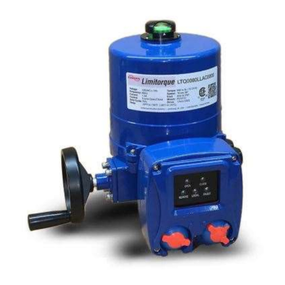
LTQ008 – LTQ230 Series 3-Phase Products User Instructions – AIIOM000165 EN 3 Product Description 3.1 General Product Description a) LTQ008 – LTQ230 The LTQ008 – LTQ230 Series are quarter-turn, electric industrial service actuators delivering up to 20,350 in-lb of torque with voltages ranging from 230V to 575V 3-phase with on/off or proportional control modes. These NEMA 4X and IP67 compliant units are equipped with two volt-free Form A auxiliary switches rated at, up to, 10A 250VAC, torque switches, and a standard clutch-free, manual-override handwheel. -
Page 11: Shipping And Handling
LTQ008 – LTQ230 Series 3-Phase Products User Instructions – AIIOM000165 EN 3.2 Shipping and Handling This actuator arrives in the fully CW (0°) position. The red/green position indicator should show all red to denote this. The actuator has a red and green position indicator on the top of the unit. The red color in the indicator window means the actuator is fully CW (0°), while the green color means the actuator is fully CCW (90°). -
Page 12: Installation
LTQ008 – LTQ230 Series 3-Phase Products User Instructions – AIIOM000165 EN 4.1 Installation - This User Instructions manual references the LTQ008-230 Series actuator rotation direction while viewed from above the actuator. All LTQ008-203 Series actuators rotate CW to drive the output shaft (bottom of the actuator) to the 0°... -
Page 13: Theory Of Operation
(i.e. switchgear “cabinet”), depending on site requirements and the actuator series chosen. Flowserve offers several types of three-phase actuators that are designed to fit applications ranging from basic controls to fully-optioned solutions. These various strategies form the levels described below which allow a product to fit functionally and economically into most three-phase applications. -
Page 14: Ltq008 - Ltq230 Bic (230/3 - 480/3 On/Off Control)
LTQ008 – LTQ230 Series 3-Phase Products User Instructions – AIIOM000165 EN 5.2 LTQ008 – LTQ230 BIC (230/3 – 480/3 On/Off Control) These models are designed to be used where there are no existing MCCs. Typically, these are used in new facilities, or where additions to existing switch gears have available space limitations or is otherwise just not feasible. -
Page 15: Ltq008 - Ltq230 Bic (230/3 - 480/3 Proportional Control)
LTQ008 – LTQ230 Series 3-Phase Products User Instructions – AIIOM000165 EN 5.3 LTQ008 – LTQ230 BIC (230/3 – 480/3 Proportional Control) These models are designed to be used where there are no existing MCCs. Typically, these are used in new facilities, or where additions to existing switch gears have available space limitations or is otherwise just not feasible. -
Page 16: Ltq008 - Ltq230 Bic + Ll (230/3 - 480/3 On/Off Control)
LTQ008 – LTQ230 Series 3-Phase Products User Instructions – AIIOM000165 EN 5.4 LTQ008 – LTQ230 BIC + LL (230/3 – 480/3 On/Off Control) These advanced, stand-alone actuators are designed to be installed in new construction sites, or existing sites, where there are no MCCs. These advanced, three-phase actuators have several versions that continue to add more features and options. -
Page 17: Ltq008 - Ltq230 Bic + Ll (230/3 - 480/3 Proportional Control)
LTQ008 – LTQ230 Series 3-Phase Products User Instructions – AIIOM000165 EN 5.5 LTQ008 – LTQ230 BIC + LL (230/3 – 480/3 Proportional Control) These advanced stand-alone actuators are designed to be installed in new constructions sites, or existing sites, where there are no existing MCCs. These advanced three-phase actuators have several versions that continue to add more features and options. -
Page 18: Torque Switches
LTQ008 – LTQ230 Series 3-Phase Products User Instructions – AIIOM000165 EN 5.6 Torque Switches - Torque switches are factory set and are not adjustable. Changing these settings will void the actuator warranty. Torque switch operation The LTQ 008-230 Series actuators have torque switches to protect the actuator, and any attached equipment, from possible damage that could occur in a high torque event. -
Page 19: Ltq Ll Series Lcs Operation
LTQ008 – LTQ230 Series 3-Phase Products User Instructions – AIIOM000165 EN 5.7 LTQ LL Series LCS Operation Operating the Local Control Station 1. The mode switch (right hand side) has three positions: i. STOP (center position) On/Off actuators: This position removes any ability to reposition the actuator electrically. -
Page 20: Adjustments
LTQ008 – LTQ230 Series 3-Phase Products User Instructions – AIIOM000165 EN 5.8 Adjustments This actuator arrives calibrated and tested by the factory to stop at 0° for the CW position and 90° for the CCW position. The auxiliary switch settings are based on the CW and CCW stops. Ideally, the auxiliary switches are set a few degrees in advance of the respective stop switches. - Page 21 LTQ008 – LTQ230 Series 3-Phase Products User Instructions – AIIOM000165 EN 5.8.1 Adjusting CW End-of-Travel 1. Reposition Mechanical Stop a. Disconnect power. b. Loosen the right-side mechanical stop. This is the CW mechanical stop limit adjustment. Using a 17 mm wrench and a 5 mm hex key, hold the jam nut and turn the stop screw 5 –...
- Page 22 LTQ008 – LTQ230 Series 3-Phase Products User Instructions – AIIOM000165 EN 5.8.2 Adjusting CCW End-of-Travel 1. Reposition Mechanical Stop a. Disconnect power. b. Loosen the left-side mechanical stop. This is the CCW mechanical stop limit adjustment. Using a 17 mm wrench and a 5 mm hex key, hold the jam nut and turn the stops screws 5 –...
- Page 23 LTQ008 – LTQ230 Series 3-Phase Products User Instructions – AIIOM000165 EN 5.8.3 Adjusting Auxiliary Switches 1. Adjust CW auxiliary cams a. Cam 3 (red) and cam 5 (red) control the CW auxiliary switch adjustments. These cams can alert the user to the actuator’s position prior to being fully opened or closed –...
-
Page 24: Commissioning
LTQ008 – LTQ230 Series 3-Phase Products User Instructions – AIIOM000165 EN 6 Commissioning - The factory sets and tests the end-of-travel stops (cams) of this actuator to respond between 0° and 90° of rotation. If the end stops require no changes, this unit is ready for immediate operation using the following procedure. -
Page 25: Bic Commissioning - On/Off Control
LTQ008 – LTQ230 Series 3-Phase Products User Instructions – AIIOM000165 EN the actuator and refer to the Table of Contents for the section to reference for the corrective action needed. 6. If the actuator stops at the correct positions, the actuator can be put into service and is fully operational. 6.2 BIC Commissioning - On/Off Control - Allowing the motor to drive the gear train into the mechanical stop will result in severe damage to the actuator! Remove power from this device before making any travel adjustments. -
Page 26: Lcs Commissioning For Bic + Ll On/Off Control
LTQ008 – LTQ230 Series 3-Phase Products User Instructions – AIIOM000165 EN a. If it does NOT, check the polarity of the incoming analog signal to make sure it is (+)12mA. b. Return to step 3. ii. If the actuator moves momentarily and then STOPS at the mid stroke position, proceed to step 4. iii. -
Page 27: Lcs Commissioning For Bic + Ll Proportional Control
LTQ008 – LTQ230 Series 3-Phase Products User Instructions – AIIOM000165 EN g. When the actuator reaches its fully CCW (90°) end-of-travel position, the OPEN LED indicator will stay illuminated on the face of the LCS. 5. Place the move switch in the CW (0°) position, and drive to approximately mid-travel, then stop. 6. - Page 28 LTQ008 – LTQ230 Series 3-Phase Products User Instructions – AIIOM000165 EN c. When the actuator reaches its fully CW (0°) end-of-travel position, the CLOSE LED indicator will stay illuminated on the face of the LCS. 6. Place the LCS move switch in the CCW (90°) position, and verify that the direction of the position indicator is CCW.
-
Page 29: Calibration
LTQ008 – LTQ230 Series 3-Phase Products User Instructions – AIIOM000165 EN 7 Calibration 7.1 Calibration Procedure for BIC On/Off Control - Allowing the motor to drive the gear train into the mechanical stop will result in severe damage to the actuator! Remove power from this device before making any travel adjustments. 1. -
Page 30: Calibration Procedure For Bic Proportional Control
LTQ008 – LTQ230 Series 3-Phase Products User Instructions – AIIOM000165 EN 7.2 Calibration Procedure for BIC Proportional Control - Allowing the motor to drive the gear train into the mechanical stop will result in severe damage to the actuator! Remove power from this device before making any travel adjustments. After completing all mounting and wiring procedures, and main power is available, it is now possible to commission the actuator. - Page 31 LTQ008 – LTQ230 Series 3-Phase Products User Instructions – AIIOM000165 EN Figure 31: Proportional PCB 3 -phase details (24 V controller) Page 30 of 40...
-
Page 32: Calibration Procedure For Bic + Ll Control Station Proportional Control
LTQ008 – LTQ230 Series 3-Phase Products User Instructions – AIIOM000165 EN 7.3 Calibration Procedure for BIC + LL Control Station Proportional Control After completing all mounting and wiring procedures, and main power is available, it is now possible to commission the actuator. 1. -
Page 33: Troubleshooting Guide
After completing all mounting and wiring procedures, and main power is available, if the actuator does not respond as expected, the following procedure(s) may help in identifying the problem. If problems still exist after consulting Table and Table , contact Flowserve for additional support. Table 2: Fault symptoms for on/off control models T h e a c t u a t o r d o e s n o t m o v e w h e n c o m m a n d e d t o d o s o . - Page 34 LTQ008 – LTQ230 Series 3-Phase Products User Instructions – AIIOM000165 EN Table 3: Fault symptoms for proportional control models T h e a c t u a t o r d o e s n o t m o v e w h e n c o m m a n d e d t o d o s o . ...
-
Page 35: Technical Data
LTQ008 – LTQ230 Series 3-Phase Products User Instructions – AIIOM000165 EN 9 Technical Data 9.1 Nameplate Page 34 of 40... -
Page 36: Torque Requirements
LTQ008 – LTQ230 Series 3-Phase Products User Instructions – AIIOM000165 EN 9.2 Torque Requirements Table 4: Actuator specifications for 3-phase models Actuator LTQ008 LTQ017 LTQ034 LTQ053 LTQ070 LTQ088 LTQ150 LTQ203 Supply Torque Output (in-lb / N m) 880 / 100 1770 / 200 3540 / 400 5310 / 600... -
Page 37: Ltq Ncu And Bic Units
LTQ008 – LTQ230 Series 3-Phase Products User Instructions – AIIOM000165 EN 9.3 LTQ NCU and BIC Units Figure 35: Exploded view of the NCU and BIC units Page 36 of 40... -
Page 38: Ltq Bic + Led Units
LTQ008 – LTQ230 Series 3-Phase Products User Instructions – AIIOM000165 EN 9.4 LTQ BIC + LED Units Figure 36: Exploded view of BIC + LED units Page 37 of 40... -
Page 39: Wire Sizing
LTQ008 – LTQ230 Series 3-Phase Products User Instructions – AIIOM000165 EN 9.5 Wire Sizing Wire sizing data is provided in Table below to assist in the selection of the proper wire size for LTQ008 Series actuators using various wire sizes over distance. Always reference the correct voltage, and do not exceed the indicated length of the wire run for each model. -
Page 40: Annex A: Glossary
LTQ008 – LTQ230 Series 3-Phase Products User Instructions – AIIOM000165 EN Annex A: Glossary Below are terms and definitions used throughout this manual: BAS is an industry acronym for a building automation system. BIC is an industry acronym for Basic Integral Controls. CCW denotes the Counterclockwise direction for movement. - Page 41 Flowserve Corporation has established industry leadership in the design and manufacture of its products. When properly selected, this Flowserve product is designed to perform its intended function safely during its useful life. However, the purchaser or user of Flowserve products should be aware that Flowserve product might be used in numerous application under a wide variety of industrial service conditions.
Need help?
Do you have a question about the Limitorque LTQ008 and is the answer not in the manual?
Questions and answers