
Related Manuals for Flowserve FlowAct Series


Summary of Contents for Flowserve FlowAct Series
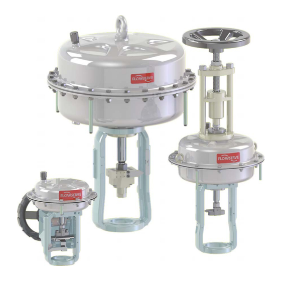
- Page 1 USER INSTRUCTIONS FlowAct Installation Diaphragm Linear Actuator Operation FCD VLENIMFACTA4 10/16 Maintenance Experience in Motion...
-
Page 2: Table Of Contents
FlowAct is manufactured to ISO 9001 standards. The following instructions are designed to assist in unpacking, installing and performing maintenance as required on Flowserve FlowAct diaphragm linear actuators. This instruction manual does not include specific product design data. Such data can be found on the actuator’s serial plate or specification documents;... -
Page 3: Scope Of Manual
- Industrial Process Control Valves (DIN EN 1349 and VDE linear actuator: 0409-1349). • Preferable for Flowserve - Villach valve product lines The FlowAct actuator is designed for use in MODERATE and • For the product range of WORLDWIDE environmental conditions, standard ambient tem- perature range -40°C to +80°C (-40°F to 176°F). -
Page 4: Storage
FlowAct Diaphragm Linear Actuator FCD VLENIMFACTA4 10/16 follow HPE standards. (Nonreturnable packaging may contain Unauthorized modification of the FlowAct dia- up to 90% recyclable materials.) phragm linear actuator voids the product test certification and product warranties, could dras- 7 Storage tically affect product performance and could be hazardous to personnel and equipment. -
Page 5: Installation
• Promptly touch up any damage to the paint that of- fers corrosion protection. • Contact your shipper immediately to report any damage. • Call your Flowserve representative if you experience any problems. Do not remove the protective covers from the air supply connection of the actuator or from the instrument ports of the actuator and accessories until the actuator is ready for installation at the site. - Page 6 FlowAct Diaphragm Linear Actuator FCD VLENIMFACTA4 10/16 Check Possible malfunction or safety related incident Confirm that the ambient temperature is not elevated A sustained exceeding of the permissible ambient temperature permanent above 160 °F (70 °C)(unless restricted by of 18 °F (10 °C) may halves the lifetime of non-metallic com- the accessories).
- Page 7 Packing Design -> adjustable -> Ø B = 65 mm, M = 105 mm, G = M12, Ø D = 95 mm and H = 20 mm only ! Packing Design -> spring loadet -> Ø B = 82 mm, M = 170 mm, G = M12 only ! Table 2: Basic safety massages for installing the actuator flowserve.com...
-
Page 8: Assembly On Valve
FlowAct diaphragm linear actuator. lowed to be assembled and reassembled only Only Flowserve trained and authorized personnel are allowed by qualified staff - personnel who are familiar to repair (disassemble and reassemble) the FlowAct in haz- with assembling, reassembling, installation and ardous areas. - Page 9 12. Adjust the stroke indicator scale so that the zero mark is in conjunction with the stroke indicator. 13. Perform three full strokes and check if the stroke indi- cator scale correspond with the end positions. Figure 7: Stroke adjusting flowserve.com...
-
Page 10: Actuator Quick-Check
FlowAct Diaphragm Linear Actuator FCD VLENIMFACTA4 10/16 Reassemble the valve into the pipe 2. Install the valve so that the actuator is in an upright po- sition whenever possible. Vertical installation permits 1. Remove the protective flange covers and coating from easier actuator maintenance. -
Page 11: Actuator Maintenance
Overhaul or replace actuator after of actuator actuator is supply alarm healthy Check health parameter Warn- No action - Start step test Overhaul or replace positioner after of positioner positioner is alarm healthy Table 6: Service activities check list flowserve.com... -
Page 12: Troubleshooting
FlowAct Diaphragm Linear Actuator FCD VLENIMFACTA4 10/16 Prior to valve maintenance it is required that you check the following conditions to reduce the risk of malfunction and safety related incidents. Check Possible malfunction or safety related incident Check for signs of leakage through the case bolting Tighten the case bolting nuts. -
Page 13: Operating The Handwheel
The FlowAct linear actuator is allowed to be disassembled and reassembled only by qualified staff - personnel who are familiar with disassembling, reassembling, installation and commissioning of this product, and possess the relevant qualifications in their field of activity. flowserve.com... - Page 14 FlowAct linear actuator. service only be disassembled and reassembled in clean rooms Only Flowserve trained and authorized personnel are allowed (ISO 14644- ISO 8, US FED STD 209 E - M 6.5, or equivalent). Pneumatic actuator are pressure vessels.
- Page 15 8. Disconnect the air supply from the actuator if appli- individual module and not the entire actuator. We ask for your cable. understanding. 9. Lift off the actuator safely. 10. Place the actuator on an assembly table and fix the yoke for disassembly. flowserve.com...
- Page 16 FlowAct Diaphragm Linear Actuator FCD VLENIMFACTA4 10/16 Reassemble the Actuator onto the valve: 1. Mount the actuator onto the bonnet and tighten the 9. Check handwheel-side for correct limit position, if yoke lock nut (76) clockwise. applicable. The legs of the yoke should be parallel NOTICE 10.
- Page 17 IAS-yoke only noid valve mounting mounting see page 34 see page 35 see page 36 see pages 37 - 38 flowserve.com...
- Page 18 FlowAct Diaphragm Linear Actuator FCD VLENIMFACTA4 10/16 Actuator without attachments Spring-to-close Disassembly instruction of the actuator subas- Reassembly instruction of the actuator subas- sembly sembly Limit disassembly only to necessary compo- Always replace parts showing wear with NOTICE NOTICE nents. new parts.
- Page 19 Scraper Ring 6.10 O-Ring 6.23 Spring Adjusting Plate 6.3.1 Hexagon Bolt - short 6.3.2 Hexagon Bolt - long Plain Washer 6.25 Protection Sleeve 6.20 Special Nut 6.19 Lock Washer Hexagon Nut Table 13: Actuator parts Figure 10: Actuator parts flowserve.com...
- Page 20 FlowAct Diaphragm Linear Actuator FCD VLENIMFACTA4 10/16 Actuator without attachments Spring-to-open Reassembly instruction of the actuator subas- Disassembly instruction of the actuator subas- sembly sembly Always replace parts showing wear with Limit disassembly only to necessary compo- NOTICE NOTICE new parts. nents.
- Page 21 Scraper Ring 6.10 O-Ring 6.23 Spring Adjusting Plate 6.3.1 Hexagon Bolt - short 6.3.2 Hexagon Bolt - long Plain Washer 6.25 Protection Sleeve 6.20 Special Nut 6.19 Lock Washer Hexagon Nut Table 14: Actuator parts Figure 11: Actuator parts flowserve.com...
- Page 22 FlowAct Diaphragm Linear Actuator FCD VLENIMFACTA4 10/16 Actuator with attachments Spring-to-close Disassembly instruction of the actuator subas- Reassembly instruction of the actuator subas- sembly sembly Limit disassembly only to necessary compo- Always replace parts showing wear with NOTICE NOTICE nents. new parts.
- Page 23 O-Ring (2x) O-Ring 6.23 Spring Adjusting Plate 6.3.1 Hexagon Bolt - short 6.3.2 Hexagon Bolt - long Plain Washer 6.25 Protection Sleeve 6.29 Stem 6.19 Lock Washer Hexagon Nut 6.24 Guide Bushing Table 15: Actuator parts Figure 12: Actuator parts flowserve.com...
- Page 24 FlowAct Diaphragm Linear Actuator FCD VLENIMFACTA4 10/16 Actuator with attachments Spring-to-open Reassembly instruction of the actuator subas- Disassembly instruction of the actuator subas- sembly sembly Always replace parts showing wear with Limit disassembly only to necessary compo- NOTICE NOTICE new parts. nents.
- Page 25 O-Ring (2x) O-Ring 6.23 Spring Adjusting Plate 6.3.1 Hexagon Bolt - short 6.3.2 Hexagon Bolt - long Plain Washer 6.25 Protection Sleeve 6.29 Stem 6.19 Lock Washer Hexagon Nut 6.24 Guide Bushing Table 16: Actuator parts Figure 13: Actuator parts flowserve.com...
- Page 26 FlowAct Diaphragm Linear Actuator FCD VLENIMFACTA4 10/16 Actuator with Handwheel - light Spring-to-close Disassembly instruction of the handwheel subas- lock nut (256) clockwise. sembly NOTICE Use a rounded chisel and a hammer. Limit disassembly only to necessary compo- NOTICE nents. 9.
- Page 27 9. Mount the handwheel onto the actuator and tighten the lock nut (256) clockwise. HandWheel NOTICE Use a rounded chisel and a hammer. Item # Part Actuator 5.11 Lock Nut 6.30 Hex Nut 6.31 Carrier Table 18: Handwheel parts Figure 15: Handwheel parts flowserve.com...
- Page 28 FlowAct Diaphragm Linear Actuator FCD VLENIMFACTA4 10/16 Actuator with Handwheel - heavy Spring-to-close or -open Disassembly instruction of the handwheel subas- 14. Lubricate the threads of the actuator and handwheel- parts with an appropriate lubricant. sembly Limit disassembly only to necessary compo- NOTICE 15.
- Page 29 Stem 6.66 Closure Screw 6.55 Pipe Section 6.57 Bearing Flange 6.40 Flange - top 6.38 Flange - bottom Actuator 6.58 Threaded Bushing 6.42 Handwheel 6.56 Stud Bolt (4x) 6.34 Threaded Ring Table 19: Handwheel parts Figure 16: Handwheel parts flowserve.com...
- Page 30 FlowAct Diaphragm Linear Actuator FCD VLENIMFACTA4 10/16 Actuator with Handwheel - heavy > Offshore - Design < Spring-to-close or -open Disassembly instruction of the handwheel subas- 14. Lubricate the threads of the actuator and handwheel- parts with an appropriate lubricant. sembly Limit disassembly only to necessary compo- NOTICE...
- Page 31 Closure Screw 6.69 Position Indicator 6.55 Pipe Section 6.57 Bearing Flange 6.40 Flange - top 6.38 Flange - bottom 6.58 Threaded Bushing Actuator 6.42 Handwheel 6.56 Stud Bolt (4x) 6.34 Threaded Ring Table 20: Handwheel parts Figure 17: Handwheel parts flowserve.com...
- Page 32 FlowAct Diaphragm Linear Actuator FCD VLENIMFACTA4 10/16 Actuator with Stroke Limitation Spring-to-close or -open Disassembly instruction of the stroke limitation NOTICE Use a rounded chisel and a hammer. subassembly Limit disassembly only to necessary compo- NOTICE 14. Mount the lock nuts (350, 2x) clockwise. nents.
- Page 33 6.112 Plain Washer 6.103 Yoke Rod (3x) 6.106 Yoke Plate 6.113 Hex Nut 6.101 Stem 6.111 Cover Actuator 6.104 Hexagon Nut 6.105 Stud Bolt 6.110 Pipe Section 6.102 Flange Table 21: Stroke limitation parts Figure 18: Stroke limitation parts flowserve.com...
- Page 34 FlowAct Diaphragm Linear Actuator FCD VLENIMFACTA4 10/16 Actuator with NAMUR-yoke Spring-to-close or -open Reassembly instruction of the yoke Disassembly instruction of the yoke Limit disassembly only to necessary compo- NOTICE 8. Lubricate the threads of the actuator and stroke cou- pling-parts with an appropriate lubricant.
- Page 35 Socket Head Screw (2x) Actuator Coupling 5.11 Actuator Locknut 6.50 O-Ring 6.51 O-Ring 5.12 Washer (4x) 5.19 Washer Lock Nut Valve Coupling Hex Bolt (4x) Depending on the valve series (see page 7). Table 23: Actuator parts Figure 20: Actuator parts flowserve.com...
- Page 36 FlowAct Diaphragm Linear Actuator FCD VLENIMFACTA4 10/16 Actuator with IAS-yoke Spring-to-close or -open Disassembly instruction of the yoke Reassembly instruction of the yoke Limit disassembly only to necessary compo- NOTICE 8. Lubricate the threads of the actuator and stroke cou- nents.
- Page 37 Hex Bolt (4x) Yoke Stroke Scale Stroke Indicator Socket Head Screw (2x) Actuator Coupling 5.11 Actuator Locknut 6.50 O-Ring 6.51 O-Ring Lock Nut Valve Coupling 6.90 Lateral Handwheel (Unit) Hex Bolt Table 25: Actuator parts Figure 22: Actuator parts flowserve.com...
- Page 38 FlowAct Diaphragm Linear Actuator FCD VLENIMFACTA4 10/16 Actuator with Handwheel - side > Type 503, 701 < Spring-to-close or -open Disassembly instruction of the yoke 7. Store all coupling and yoke-parts safely, lose no parts. 8. For disassemble the attachments see pages 26 - 33 Limit disassembly only to necessary compo- NOTICE and for actuator subassembly see pages 18 - 25.
- Page 39 42 - 43 see pages 44 - 45 see pages 46 - 47 Central-mounted handwheel without see pages 50 - 53 NAMUR-yoke, with double mounting pads Side-mounted handwheel - maximal positioning force 39 kN see page 54 see page 55 flowserve.com...
- Page 40 FlowAct Diaphragm Linear Actuator FCD VLENIMFACTA4 10/16 Actuator without attachments Reassembly instruction of the actuator subas- sembly Spring-to-close Always replace parts showing wear with NOTICE new parts. Disassembly instruction of the actuator subas- sembly 13. Lubricate the new O-ring (275), new scraper ring (273) Limit disassembly only to necessary compo- with an appropriate lubricant and install into the guide NOTICE...
- Page 41 Plain Washer 6.25 Protection Sleeve (4x) 6.20 Special Nut 6.19 Lock Washer Hexagon Nut 6.47 Distance Bushing Alternatively, hex head assembled screws with captive flat washers are used for this application. Table 27: Actuator parts Figure 24: Actuator parts flowserve.com...
- Page 42 FlowAct Diaphragm Linear Actuator FCD VLENIMFACTA4 10/16 Actuator without attachments Spring-to-open Reassembly instruction of the actuator subas- Disassembly instruction of the actuator subas- sembly sembly Always replace parts showing wear with NOTICE Limit disassembly only to necessary compo- NOTICE new parts. nents.
- Page 43 Plain Washer (24x) 6.25 Protection Sleeve 6.20 Special Nut 6.19 Lock Washer Hexagon Nut 6.47 Distance Bushing Alternatively, hex head assembled screws with captive flat washers are used for this application. Table 28: Actuator parts Figure 25: Actuator parts flowserve.com...
- Page 44 FlowAct Diaphragm Linear Actuator FCD VLENIMFACTA4 10/16 Actuator with attachments Spring-to-close Disassembly instruction of the actuator subas- Reassembly instruction of the actuator subas- sembly sembly Limit disassembly only to necessary compo- Always replace parts showing wear with NOTICE NOTICE nents. new parts.
- Page 45 6.25 Protection Sleeve 6.20 Stem 6.19 Lock Washer Hexagon Nut (24x) 6.47 Distance Bushing 6.83 Guide Bushing Alternatively, hex head assembled screws with captive flat washers are used for this application. Table 29: Actuator parts Figure 26: Actuator parts flowserve.com...
- Page 46 FlowAct Diaphragm Linear Actuator FCD VLENIMFACTA4 10/16 Actuator without attachments Spring-to-open Reassembly instruction of the actuator subas- Disassembly instruction of the actuator subas- sembly sembly Always replace parts showing wear with NOTICE Limit disassembly only to necessary compo- NOTICE new parts. nents.
- Page 47 Protection Sleeve (4x) 6.20 Stem 6.19 Lock Washer Hexagon Nut (24x) 6.47 Distance Bushing 6.83 Guide Bushing Alternatively, hex head assembled screws with captive flat washers are used for this application. Table 30: Actuator parts Figure 27: Actuator parts flowserve.com...
- Page 48 FlowAct Diaphragm Linear Actuator FCD VLENIMFACTA4 10/16 Actuator with Stroke Limitation Spring-to-close or -open Disassembly instruction of the stroke limitation 15. Lower the yoke plate (378) onto the stud bolt (385) on the yoke rods (377). subassembly 16. Install the plain washers (334) and socket head screws Limit disassembly only to necessary compo- NOTICE (333) and finger tighten it clockwise.
- Page 49 Plain Washer (3x) 6.109 Lock Nut (4x) 6.112 Plain Washer 6.103 Yoke Rod (3x) Actuator 6.106 Yoke Plate 6.113 Hex Nut 6.101 Stem 6.111 Cover 6.105 Stud Bolt 6.110 Pipe Section Table 31: Stroke limitation parts Figure 28: Stroke limitation parts flowserve.com...
- Page 50 FlowAct Diaphragm Linear Actuator FCD VLENIMFACTA4 10/16 Actuator with Handwheel - central Spring-to-close Reassembly instruction of the handwheel subas- Disassembly instruction of the handwheel subas- sembly sembly Always replace parts showing wear with Limit disassembly only to necessary compo- NOTICE NOTICE nents.
- Page 51 Stem Extension 5.11 Lock Nut 6.122 Stem End Stop 6.121 Cover Tube 6.124 Lock Nut 6.96 Hex Socket Set Screw 6.42 Central Handwheel (Unit) 6.123 Slotted Set Screw (4x) Table 32: Handwheel “central“ parts Figure 29: Handwheel “central“ parts flowserve.com...
- Page 52 FlowAct Diaphragm Linear Actuator FCD VLENIMFACTA4 10/16 Actuator with Handwheel - central Spring-to-open Reassembly instruction of the handwheel subas- Disassembly instruction of the handwheel subas- sembly sembly Always replace parts showing wear with Limit disassembly only to necessary compo- NOTICE NOTICE nents.
- Page 53 Stem Extension 5.11 Lock Nut 6.122 Stem End Stop 6.121 Cover Tube 6.124 Lock Nut 6.96 Hex Socket Set Screw 6.42 Central Handwheel (Unit) 6.123 Slotted Set Screw (4x) Table 33: Handwheel “central“ parts Figure 30: Handwheel “central“ parts flowserve.com...
- Page 54 FlowAct Diaphragm Linear Actuator FCD VLENIMFACTA4 10/16 Actuator with yoke Spring-to-close or -open Disassembly instruction of the yoke Reassembly instruction of the yoke Limit disassembly only to necessary compo- 8. Lubricate the threads of the actuator and stroke cou- NOTICE pling-parts with an appropriate lubricant.
- Page 55 Socket Head Screw (2x) Stroke Indicator Socket Head Screw (4x) Actuator Coupling 5.11 Actuator Locknut 5.12 Plain Washer 5.19 Plain Washer (2x) Lock Nut Valve Coupling 6.95 Lateral Handwheel (Unit) Hex Bolt Table 35: Coupling parts Figure 32: Coupling parts flowserve.com...
- Page 56 FlowAct Diaphragm Linear Actuator FCD VLENIMFACTA4 10/16 Space for personal notes...
- Page 57 Spring-to-open Spring-to-close Spring-to-open see pages 58 - 61 see pages 62 - 65 see pages 66 - 69 see pages 70 - 73 Central-mounted handwheel without see pages 50 - 53 NAMUR-yoke, with double mounting pads see page 54 flowserve.com...
- Page 58 FlowAct Diaphragm Linear Actuator FCD VLENIMFACTA4 10/16 Actuator without attachments Spring-to-close and O-ring (276). Danger of life in case of improper WARNING disassembly. The maximum sum 10. Disassemble the hexagon bolts (335), plain washers of the spring preload can be 60 000 N ! (337) and hexagon nuts (351).
- Page 59 Position the diaphragm-stem unit NOTICE such that the air connection and the Arrange the distance bushing like an NOTICE Mark align. correctly wearing hat. The internal stroke stop takes over the special nut. 31. Install and align the actuator springs (229). flowserve.com...
- Page 60 FlowAct Diaphragm Linear Actuator FCD VLENIMFACTA4 10/16 43. Lubricate the thread of the stem extension (348) with an appropriate lubricant and install and finger tighten the special nut (348). The diaphragm plate should be posi- NOTICE tioned to the diaphragm with the aid of the positioning template.
- Page 61 FlowAct Diaphragm Linear Actuator FCD VLENIMFACTA4 10/16 Figure 33: Actuator parts flowserve.com...
- Page 62 FlowAct Diaphragm Linear Actuator FCD VLENIMFACTA4 10/16 Actuator without attachments Spring-to-open remove the O-rings (279), diaphragm casing (202) Danger of life in case of improper WARNING and O-ring (276). disassembly. The maximum sum of the spring preload can be 60 000 N ! 10.
- Page 63 If these will ignored the spring to the actuators center. If these will ignored the spring may touch the actuators casing and rub in rare cases. may touch the actuators casing and rub in rare cases. flowserve.com...
- Page 64 FlowAct Diaphragm Linear Actuator FCD VLENIMFACTA4 10/16 44. Lubricate the new O-ring (272) with an appropriate lubricant. 56. Log the maintenance interval and the work performed. 45. Lower the distance bushing (374), spacer bushing 57. The actuator subassembly is ready to be mounted on (228), disk (220), diaphragm plate (227), the valve and the accessories attached.
- Page 65 FlowAct Diaphragm Linear Actuator FCD VLENIMFACTA4 10/16 Figure 34: Actuator parts flowserve.com...
- Page 66 FlowAct Diaphragm Linear Actuator FCD VLENIMFACTA4 10/16 Actuator with attachments Spring-to-close and O-ring (276). Danger of life in case of improper WARNING disassembly. The maximum sum 10. Disassemble the hexagon bolts (335), plain washers of the spring preload can be 60 000 N ! (337) and hexagon nuts (351).
- Page 67 Position the diaphragm-stem unit NOTICE such that the air connection and the Arrange the distance bushing like an NOTICE Mark align. correctly wearing hat. The internal stroke stop takes over the special nut. 31. Install and align the actuator springs (229). flowserve.com...
- Page 68 FlowAct Diaphragm Linear Actuator FCD VLENIMFACTA4 10/16 43. Lubricate the thread of the stem extension (380) with an appropriate lubricant and install and finger tighten the stem (348). The diaphragm plate should be posi- NOTICE tioned to the diaphragm with the aid of the positioning template.
- Page 69 FlowAct Diaphragm Linear Actuator FCD VLENIMFACTA4 10/16 Figure 35: Actuator parts flowserve.com...
- Page 70 FlowAct Diaphragm Linear Actuator FCD VLENIMFACTA4 10/16 Actuator with attachments Spring-to-open 9. Loosen the hexagon bolts (334) counterclockwise and Danger of life in case of improper WARNING remove the O-rings (279), diaphragm casing (202) disassembly. The maximum sum and O-ring (276). of the spring preload can be 60 000 N ! 10.
- Page 71 If these will ignored the spring to the actuators center. If these will ignored the spring may touch the actuators casing and rub in rare cases. may touch the actuators casing and rub in rare cases. flowserve.com...
- Page 72 FlowAct Diaphragm Linear Actuator FCD VLENIMFACTA4 10/16 44. Lubricate the new O-ring (272) with an appropriate lubricant. 56. Log the maintenance interval and the work performed. 45. Lower the distance bushing (374), spacer bushing 57. The actuator subassembly is ready to be mounted on (228), disk (220), diaphragm plate (227), the valve and the accessories attached.
- Page 73 FlowAct Diaphragm Linear Actuator FCD VLENIMFACTA4 10/16 Figure 36: Actuator parts flowserve.com...
-
Page 74: Torque Requirements
FlowAct Diaphragm Linear Actuator FCD VLENIMFACTA4 10/16 16 Torque Requirements Torque Requirements for VALVE / ACTUATOR LOCK NUT (76, 256) per actuator size Unit 1502 3002 Tighten the lock nut clockwise with a rounded chisel and a 1,5 kg (3.5 lbs) hammer before occurs the kickback effect. -
Page 75: Disposal
Permissible limit values must be maintained to en- sure suitable protective measures; service personnel must be properly instructed in performing the disassembly and reas- sembly procedure. flowserve.com... - Page 76 Flowserve Corporation has established industry leadership in the design and manufacture of its products. When properly selected, this Flowserve product is designed to perform its intended function safely during its useful life. However, the purchaser or user of Flowserve products should be aware that Flowserve products might be used in numerous applications under a wide variety of industrial service conditions.
Need help?
Do you have a question about the FlowAct Series and is the answer not in the manual?
Questions and answers