
Related Manuals for Flowserve Limitorque QX


Summary of Contents for Flowserve Limitorque QX
- Page 1 USER INSTRUCTIONS Limitorque QX Electronic Actuator Installation Operation FCD LMENIM3306-06 – 07/14 Maintenance Experience In Motion...
-
Page 2: Table Of Contents
Limitorque QX Electronic Actuator FCD LMENIM3306-06 – 07/14 Contents Important Notes Quick Start 2.1 Calibrate – Position Limits 2.1.1 Electrical Operation Feature 2.1.2 Handwheel Operation Feature 2.1.3 Entering the Setup Mode 2.2 DDC Option 2.3 Check the Settings Installation and Operation 3.1 Preparing the Stem Nut... - Page 3 Limitorque QX Electronic Actuator FCD LMENIM3306-06 – 07/14 4.9 Modutronic Option 4.9.1 Status 4.9.2 Proportional Band 4.9.3 Fail Position 4.9.4 Deadband 4.9.5 Polarity (20 mA) 4.9.6 Delay After Stop 4.9.7 4-20 mA Signal Range 4.9.8 Set High Reference 4.9.9 Set Low Reference 4.9.10 Modutronic LCD Display...
- Page 4 Limitorque QX Electronic Actuator FCD LMENIM3306-06 – 07/14 4.16 Change Analog Out 4.16.1 APT Polarity Option 4.16.2 ATT Polarity Option 4.17 Remote Mode 4.18 Local Control 4.18.1 LED Customization 4.19 ESD (Emergency Shutdown) Overrides 4.19.1 ESD Override 4.19.2 Inhibit 4.19.3 Local Command 4.19.4 Stop...
- Page 5 Limitorque QX Electronic Actuator FCD LMENIM3306-06 – 07/14 Figures Figure 1.1 – QX-05 Actuator Figure 2.1 – Electrical operation Figure 2.2 – Handwheel operation Figure 2.3 – QX travel stops Figure 3.1 – Top view - stem nut with standard keyway position Figure 3.2 –...
- Page 6 Limitorque QX Electronic Actuator FCD LMENIM3306-06 – 07/14 Figure 4.32 – Monitor relay Figure 4.33 – Diagnostic reset Figure 4.34 – TAG number Figure 4.35 – LCD contrast Figure 4.36 – Motor thermostat Figure 4.37 – Change valve data Figure 4.38 – Change port and Bluetooth settings Figure 5.1 –...
-
Page 7: Important Notes
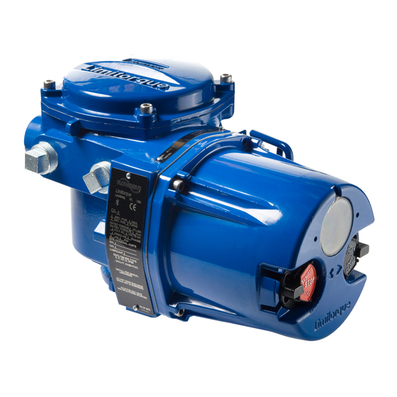
Limitorque QX Electronic Actuator FCD LMENIM3306-06 – 07/14 Figure 1.1 – QX-05 Actuator OPTIONAL Piece Description Piece Description Piece Description Handwheel Control Knob Motor Declutch Lever (QX-05) Ground Lug Certification Nameplate Oil Fill Baseplate Tag Nameplate Controls Cover Conduit Entry... - Page 8 Limitorque QX Electronic Actuator FCD LMENIM3306-06 – 07/14 NOTE: Removal of any cover, other than the terminal compartment cover, will invalidate the unit warranty. Exposure of actuator components to an environment that results in deterioration of internal components will also invalidate the unit’s warranty.
-
Page 9: Quick Start
Limitorque QX Electronic Actuator FCD LMENIM3306-06 – 07/14 Quick Start Quick Start provides step-by-step instructions for commissioning each QX actuator. These instructions are for the following: • Position limits calibration – can be performed one of two ways: 1. Electrical operation: See Section 2.1.2, Electrical Operation Feature. -
Page 10: Calibrate Position Limits
Limitorque QX Electronic Actuator FCD LMENIM3306-06 – 07/14 2.1 Calibrate Position Limits 1. Confirm that the QX actuator is correctly installed on the valve as described in Section 3 Installation and Operation. 2. Refer to the nameplate for the correct main power supply voltage. Switch on the main power to the unit. - Page 11 Limitorque QX Electronic Actuator FCD LMENIM3306-06 – 07/14 CAUTION: Do not adjust close stop while stop is loaded. It is highly recommended that the stops be turned until they are almost removed from the housing before setting the limits. Once the limits have been set, then the stops maybe tightened.
-
Page 12: Handwheel Operation Feature
Limitorque QX Electronic Actuator FCD LMENIM3306-06 – 07/14 Figure 2.1 – Electrical operation Switch to STOP STOP CLOSE VALVE SAVE CLOSE SET CLOSE CLOSE VALVE CLOSE VALVE OK ? RETURN TO STOP OK ? LIMIT OK? POSITION LIMIT? LOCAL “NO ” operates... - Page 13 Limitorque QX Electronic Actuator FCD LMENIM3306-06 – 07/14 Closed Position Limit 1. “SET CLOSE POSITION LIMIT?” is displayed on the LCD. 2. Select “YES.” The “CLOSE VALVE - OK?” is displayed. 3. Depress the declutch lever, and at the same time slowly rotate the handwheel until the clutch is fully engaged.
-
Page 14: Figure 2.2 - Handwheel Operation
Limitorque QX Electronic Actuator FCD LMENIM3306-06 – 07/14 Figure 2.2 – Handwheel operation STO P YE S YE S YE S SET CLOS E CLOSE VALVE SAVE CLOS E POSITION LIMIT? OK ? LIMIT OK? Declutch actuator; Rotate handwheel to “... -
Page 15: Entering The Setup Mode
Limitorque QX Electronic Actuator FCD LMENIM3306-06 – 07/14 2.1.3 Entering the Setup Mode To access the Setup Mode after initial setup has been exited, use these steps: 1. Place the red selector knob in the “STOP” position. 2. Within 10 seconds, place the black control knob in the “YES” position, then the “NO” position, then again in the “YES”... -
Page 16: Installation And Operation
Limitorque QX Electronic Actuator FCD LMENIM3306-06 – 07/14 Installation and Operation 3.1 Preparing the Stem Nut The QX has two (2) basic base designs: • Torque-only (90º) operation • Multi-turn operation (up to 20 multi-turn rotations - 7200º total) 3.1.1 Torque Applications Standard B4/B4E Base The standard QX actuator base is the stem nut for torque-only. -
Page 17: Figure 3.1 - Top View - Stem Nut With Standard Keyway Position
Limitorque QX Electronic Actuator FCD LMENIM3306-06 – 07/14 Disassembly – Flange 2 1. Remove the two torque nut mounting screws and remove the torque nut. 2. Machine the torque nut to suit the valve stem or gearbox input shaft. Ensure sufficient clearance for a smooth, sliding fit. -
Page 18: Mechanical Installation Onto Valve Or Gearbox
Limitorque QX Electronic Actuator FCD LMENIM3306-06 – 07/14 3.2 Mechanical Installation onto Valve or Gearbox Before installing the actuator onto a valve or gearbox, check the following to ease installation: • Verify that mounting flange is suited dimensionally to mate with the actuator base. Ensure that it is perpendicular to the valve stem. -
Page 19: Sealing Cable/Conduit Entries
Limitorque QX Electronic Actuator FCD LMENIM3306-06 – 07/14 3.3.3 Sealing Cable/Conduit Entries The sealing of cables and conduit entries should be done in accordance with National Standards or the Regulatory Authorities that have certified the actuators. This is particularly true for units that are certified for use in hazardous areas where the method of sealing must be to an approved standard and cable glands, reducers, plugs, and adapters must be approved and separately certified. -
Page 20: Figure 3.4 - Terminal Block
Limitorque QX Electronic Actuator FCD LMENIM3306-06 – 07/14 Table 3.2 lists the maximum allowable voltage and current parameters for the terminal block control terminals. Table 3.2 – Terminal block rating; power terminals Description 30 AMP 20 AMP 15 AMP STD Rating... -
Page 21: Termination Of Cables
Limitorque QX Electronic Actuator FCD LMENIM3306-06 – 07/14 Table 3.3 – Terminal block rating; control terminals Low Voltage Row STD Rating Increased Safety Rating 1 points 1-16, 50 Volt 0.5 AMP AC RMS 0.45 AMP AC RMS 2 points 17-35, 125 Volt 0.5 AMP AC RMS... -
Page 22: Network Installations
Note 1: Refer to unit nameplate. 3.3.7 Network Installations The Limitorque QX offers a number of network options: DDC-Modbus, Foundation Fieldbus H1, Profibus DP_V1, Profibus PA, and DeviceNet. Ensure that the network cable type is Belden 3074F, Belden 3105, Belden 9841 or another cable that is within 5% of the following specifications. -
Page 23: Figure 3.7 - Standard Wiring Diagram - Three Phase Shown
Limitorque QX Electronic Actuator FCD LMENIM3306-06 – 07/14 Figure 3.7 – Standard wiring diagram - three phase shown NOTE: Most current wiring diagram is shipped within the terminal compartment of the QX. View of terminal block Three-phase supply Close Reversing... -
Page 24: Figure 3.9 - Separating Cable Parts
Limitorque QX Electronic Actuator FCD LMENIM3306-06 – 07/14 CAUTION: Do not melt the insulation. 6. Connect the network cables to the QX actuator terminal block per Table 3.3 and appropriate wiring diagram. Table 3.5 details a connection for the loop topology. -
Page 25: Foundation Fieldbus Installation
Limitorque QX Electronic Actuator FCD LMENIM3306-06 – 07/14 Table 3.5– Loop topology connections Terminal Block Number DATA-A1* (-) DATA-A1 (+) DATA-A2* (-) DATA-A2 (+) Surge Protection In terms of voltage, DATA is negative with respect to DATA*. NOTE: Surge protection must be grounded to be effective. -
Page 26: Network Wiring - Profibus Dp/Pa Installation
Limitorque QX Electronic Actuator FCD LMENIM3306-06 – 07/14 Cable Preparation Prepare the network cable for connection to the QX actuator terminal block as follows in Figure 3.8 through 3.11. Table 3.6 details connections for Foundation Fieldbus. Table 3.6 – Foundation Fieldbus connections... -
Page 27: Network Wiring - Devicenet
8 amps (4 amps for NEC Class 2) may be passed along the hi-way from a suitable power source. Two conductors are used for the CAN bus signals, CAN_H and CAN_L, which are usually smaller in diameter. Flowserve recommends Belden 3082A cable for connecting to a DeviceNet network. -
Page 28: Commissioning The Actuator
Limitorque QX Electronic Actuator FCD LMENIM3306-06 – 07/14 Figure 3.12 – Terminal Block Shield SHIELD-TERMINAL BLOCK M3 X 5 SELF LOCK SCREW USE QTY. OF TWO (2) M3 X 5 SELF LOCK SCREWS TO MOUNT SHIELD. USE 2 SCREWS FROM TERMINAL BLOCK OR FROM END USERS BAG. -
Page 29: Figure 3.13 - User Network Connection For Loop Topology
Limitorque QX Electronic Actuator FCD LMENIM3306-06 – 07/14 Figure 3.13 – User network connection for loop topology/ Typical for all two-wire network protocols Terminal block Earth ground Surge protection Network data-A1* Network data-A1 Network data-A2* Network data-A2 N/ C Figure 3.14 – External earth/ground connection – housing GROUNDING LUG Table 3.9 –... -
Page 30: View The Existing Settings
Limitorque QX Electronic Actuator FCD LMENIM3306-06 – 07/14 3.5.2 View the Existing Settings All the existing setup data may be viewed on the LCD display by following a simple step-by-step dialog that may be selected in the following languages: English (default), Spanish, French, German, Italian, Portuguese, Russian, Malay, Mandarin, Katakana, and Turkish. -
Page 31: Setting Position Limits
Limitorque QX Electronic Actuator FCD LMENIM3306-06 – 07/14 Figure 3.15 – View settings NOTE 1 NOTE VIEW VIEW VIEW VIEW VIEW VIEW VIEW SETTINGS? VALVE SETTINGS ? DDC? DEVICENET? REMOTE MODE? MONITOR RELAY? UNIT DATA? NOTE 1 NOTE 1 NOTE 1 VIEW VIEW STATUS &... - Page 32 Limitorque QX Electronic Actuator FCD LMENIM3306-06 – 07/14 If the calibration requires adjustment: 1. Select “NO” at the “SET OPEN POSITION LIMIT?” prompt. 2. Repeat the “SET CLOSE POSITION LIMIT?” routine. NOTE: The green LED is the default setting for indicating the (CLOSE) position.
-
Page 33: Figure 3.16 - Position Setup - Electrical Operation
Limitorque QX Electronic Actuator FCD LMENIM3306-06 – 07/14 1. Move the red knob to “LOCAL” and move the black knob in the intended direction. LCD display will read: CLOSE VALVE OPEN VALVE RETURN TO STO P RETURN TO STO P 2. -
Page 34: Operating The Qx Actuator
Limitorque QX Electronic Actuator FCD LMENIM3306-06 – 07/14 3.6 Operating the QX Actuator 3.6.1 Manual Operation Operate the actuator with the handwheel as follows: Depress the declutch lever and, at the same time, slowly rotate the handwheel until the clutch is fully engaged. -
Page 35: Remote Control
Limitorque QX Electronic Actuator FCD LMENIM3306-06 – 07/14 3.6.4 Remote Control Once the position limits have been set, and “REMOTE” mode is enabled: 1. Place the red selector knob in “REMOTE” to permit command control by a remote device. Local “OPEN/CLOSE”... -
Page 36: Table 3.10 - Led Indicators - Default Settings
Limitorque QX Electronic Actuator FCD LMENIM3306-06 – 07/14 Table 3.10 – LED Indicators – default settings LED Indicator Operation Description Yellow Green Valve is fully open (Red knob in “REMOTE”) Valve is fully close (Red knob in “REMOTE”) Blinking Valve is closing (Red knob in “REMOTE”) Blinking Valve is opening (Red knob in “REMOTE”) -
Page 37: Customizing The Actuator
Limitorque QX Electronic Actuator FCD LMENIM3306-06 – 07/14 Customizing the Actuator The actuator settings can be customized; i.e., the default settings can be changed and the purchased options can be configured. Language selection can also be customized. At the “SETUP IN ENGLISH?” prompt, select “NO” to move between the following languages: English, Spanish, German, French, Italian, Portuguese, Russian, Malay, Mandarin, Katakana, and Turkish. -
Page 38: Figure 4.1 - Entering The Setup Mode
Limitorque QX Electronic Actuator FCD LMENIM3306-06 – 07/14 7. When configuration is complete, answer “YES” to “EXIT SETUP?” Alternatively, the “SETUP” mode may be terminated at any time by moving the red selector knob from “STOP” to “LOCAL” or “REMOTE.” All the changes made so far will automatically be saved. -
Page 39: Password Entry
Limitorque QX Electronic Actuator FCD LMENIM3306-06 – 07/14 Figure 4.3 – Changing settings CHANGE CHANGE CHANGE ESD CHANGE ENTER CHANGE CHANGE CHANGE VALVE OVERRIDES? TAG? SETTINGS ? PASSWORD POSITION SETUP? 2-SPEED TIMER? DATA? PB/DP? CHANGE CHANGE CHANGE CHANGE CHANGE CHANGE... -
Page 40: New Password
Limitorque QX Electronic Actuator FCD LMENIM3306-06 – 07/14 Figure 4.4 – Password entry If password correct CHANGE ENTE R "0" 0 0 1 "0" 0 1 0 "0 " PASSWORD IS VALVE DIGIT 3 OK? 100 OK? SETUP? SETTINGS? PASSWORD? -
Page 41: Valve Setup
Limitorque QX Electronic Actuator FCD LMENIM3306-06 – 07/14 4.4 Valve Setup Valve setup enables the actuator to be changed to suit the type of valve that it is mounted on. 4.4.1 Close Direction Default = CW to Close The majority of valves require clockwise (CW) rotation of the actuator drive sleeve when viewed from above the actuator. -
Page 42: Torque Switch Timer
Limitorque QX Electronic Actuator FCD LMENIM3306-06 – 07/14 4.5 Torque Switch Timer Torque switch timer permits a user to select a time for the torque switch to time out once the actuator determines that it has reached its torque seat. The torque switch timer can be adjusted from zero (0) seconds to a maximum of ten (10) seconds. The default is five (5) seconds. -
Page 43: Operating Time
Limitorque QX Electronic Actuator FCD LMENIM3306-06 – 07/14 4.6 Operating Time All QX units are shipped with default operating time values based on unit size. The different sized units each have a specific range of operating times: • QX-1: 5-20 sec, default 15 sec •... -
Page 44: Close Torque Valve Or Open Torque Valve
Limitorque QX Electronic Actuator FCD LMENIM3306-06 – 07/14 4.7.1 Close Torque Valve or Open Torque Valve The output torque from the actuator to close or open the valve may be configured between 40% and 100% of the rated torque as stated on the actuator nameplate (See Figure 4.10), in 1% increments (unless limited by the factory). -
Page 45: Set Position Limits For Manual Operation
Limitorque QX Electronic Actuator FCD LMENIM3306-06 – 07/14 4. Inspect for correct operation. If the position limits are set adjacent to each other, then an error message will be displayed: “KEEP OPEN (CLOSE) LIMIT.” The position calibration is now complete. The actuator will function as ordered. -
Page 46: Figure 4.11 - Electrical Operation
Limitorque QX Electronic Actuator FCD LMENIM3306-06 – 07/14 Figure 4.11 – Electrical operation Switch to STO P STO P CLOSE VALVE CLOSE VALVE CLOSE VALV E SAVE CLOSE SET CLOSE RETURN T O STO P POSITION LIMIT? OK ? OK ? -
Page 47: Modutronic Option
Limitorque QX Electronic Actuator FCD LMENIM3306-06 – 07/14 4.9 Modutronic Option The Modutronic option enables the actuator to be controlled via a milliamp input signal. • If the Modutronic option has been purchased, it is automatically calibrated when position limits are set. No further adjustments are required, unless the defaults do not suit the application. -
Page 48: Delay After Stop
Limitorque QX Electronic Actuator FCD LMENIM3306-06 – 07/14 4.9.6 Delay After Stop Default setting = 0 seconds To change from the default setting, select “NO” to adjust the length of delay time after the actuator stops modulating. The delay after stop is adjustable from 0-60 seconds. -
Page 49: Modutronic Lcd Display
Limitorque QX Electronic Actuator FCD LMENIM3306-06 – 07/14 Figure 4.14 – Modutronic signals A PPLY HIGH LEVEL HIGH REFERENCE SET HIGH “ SET LOW C ONTROL SIGNA L (OK)-EXIT REFERENCE-OK? REFERENCE ” “ CHANGE SET LO W APPLY L OW LEVEL LOW REFERENCE MODUTRONIC”... -
Page 50: Network Address
Limitorque QX Electronic Actuator FCD LMENIM3306-06 – 07/14 4.10.2 Network Address Default = 1 Network address allows user to assign a unique network address to an actuator. 1. The network address must be entered in accordance with the Instrument Data Sheet, and care must be taken to ensure that the same address is not used anywhere else in the same network. -
Page 51: Proportional Band
Limitorque QX Electronic Actuator FCD LMENIM3306-06 – 07/14 4.10.6 Proportional Band Proportional band is the range of errors between position and demand signal that will produce reduced speed (pulsing). Default = 15% To change from the default, select “NO” until the required value is displayed. The value is adjustable between 1% and 100%, in 1% increments. -
Page 52: Status
Limitorque QX Electronic Actuator FCD LMENIM3306-06 – 07/14 4.11.1 Status Default = ON FF Status enables user to change from the default condition to turn on and off the digital control capability of the actuator. 4.11.2 Terminate Bus Should a user select to make this unique actuator the termination point for the network, select “YES.” If not, then “NO.”... -
Page 53: Comm Loss Delay
Limitorque QX Electronic Actuator FCD LMENIM3306-06 – 07/14 Figure 4.16 – Foundation Fieldbus CHANGE STATUS ANALOG SCALE (ON)-OK? 0-100-OK? (OFF) (0-255) (0-4095) ESD ACTION COMM LOSS ACTION COMM LOSS DELAY OPEN/CLOSE (IGNORE)-OK? (NONE)-OK? (60 SEC)-OK? MODE-OK? (CLOSE) (CLOSE) (0-4095) (OPEN) -
Page 54: Status
Limitorque QX Electronic Actuator FCD LMENIM3306-06 – 07/14 Figure 4.17 – Profibus DP CHANGE PBDP-A STATUS PBDP-B STATUS REDUNDANT MONITOR STANDBY PB ADRESS1 PB/DP? (ON)-OK? (ON)-OK? MASTER (YES)-OK? PB (ON)-OK? (0-125) Unit increments ESD ACTION COMMLOSS ACTION COMMLOSS DELAY OPEN/CLOSE... -
Page 55: Comm Loss Delay
Limitorque QX Electronic Actuator FCD LMENIM3306-06 – 07/14 13. For no COMM LOSS ACTION, select YES. For setting COMM LOSS ACTION, select NO. If POSITION is chosen, as action, COMM LOSS MOVE TO (XXX%)-OK? is displayed. Select NO to set desired position. -
Page 56: Status
Limitorque QX Electronic Actuator FCD LMENIM3306-06 – 07/14 QX Multi-control Mode Operation - The QX is equipped with the ability to hardwire to digital inputs, set-up for analog control (Modutronic), or control via network protocols. In order to utilize this feature, select “Multi-control mode”... -
Page 57: Comm Loss Delay
Limitorque QX Electronic Actuator FCD LMENIM3306-06 – 07/14 To Change from the Default Range: Select “NO” to adjust the value between 1% and 50%, in 1% increments to suit the application. Figure 4.19 – DN Option CHANGE STATUS BAUD RATE... -
Page 58: Status And Alarm Contact Default Settings
Limitorque QX Electronic Actuator FCD LMENIM3306-06 – 07/14 • “LOCAL SELECTED” – red selector knob in “LOCAL” • “MOTOR OVERTEMP” – thermistor range exceeded • “OVERTORQUE” – torque exceeded in mid-travel • “MANUAL OVERRIDE” – actuator moved by handwheel • “VALVE JAMMED” – valve can’t move •... -
Page 59: Contact
Limitorque QX Electronic Actuator FCD LMENIM3306-06 – 07/14 Figure 4.20 – Status and alarm contacts (Shown with optional boards added) R1-R4 & RM CHANGE STATUS & CHANGE CONTACTS CHANGE STATUS STATUS FUNCTION CONTACT ENABLED - OK? ALARM CONTACTS? R1-R4 & RM? -
Page 60: Stop Position
Limitorque QX Electronic Actuator FCD LMENIM3306-06 – 07/14 Select “NO” until the display indicates the required value of percentage OPEN at which the pulsing should start. Adjustable in 1% increments as listed: Closing = 0% to 99%. Opening = 1% to 100%. -
Page 61: Figure 4.22 - Change Analog Out
Limitorque QX Electronic Actuator FCD LMENIM3306-06 – 07/14 Figure 4.22 – Change Analog Out CHANGE ANALOG STATUS STATUS FUNCTION ANALOG OUT ? OUT 1? ON-OK? APT-OK? OUT 2? ON-OK? ATT-OK? Figure 4.23 – Change Analog Out Voltage – APT CALIBRATE... -
Page 62: Apt Polarity Option
Limitorque QX Electronic Actuator FCD LMENIM3306-06 – 07/14 Figure 4.25 – Change Analog Out Voltage – ATT CALIBRATE 10VDC HIGH SIGNAL? If 5VDC option selected: “5VDC” will be displayed. SAVE If 5VDC option selected: SETTINGS? “POLARITY 5VDC” will be displayed. -
Page 63: Att Polarity Option
Limitorque QX Electronic Actuator FCD LMENIM3306-06 – 07/14 3. Select “NO” to select 4 ma/0 VDC2. Select “YES” to enter the “POLARITY” display. 4. Select “NO” to choose between: 20 mA = OPEN 20 mA = CLOSE 5. Select “NO” to recalibrate new value (low end 3.4-4.5 mA; high end 19.5-21 mA) as shown on meter. New value will not be shown on display. -
Page 64: Local Control
Limitorque QX Electronic Actuator FCD LMENIM3306-06 – 07/14 4.18 Local Control “LOCAL CONTROL” mode changes how the local control switches and display are used from the default settings. Default = On & Maintain Mode NOTE: User may select to disable the LOCAL CONTROL, which prohibits the cycling of the QX from OPEN to CLOSE or REVERSE. -
Page 65: Esd Override
Limitorque QX Electronic Actuator FCD LMENIM3306-06 – 07/14 4.19.1 ESD Override It may be desirable that ESD override other events. These events are selectable. The “>” symbol after ESD indicates that ESD will override that particular event. Sections 4.19.2 through 4.19.12 list the choices. -
Page 66: Lost Phase
Limitorque QX Electronic Actuator FCD LMENIM3306-06 – 07/14 • “ESD>JAMMED VALVE” – ESD overrides jammed valve indication • “JAMMED VALVE>ESD” – Jammed valve indication overrides ESD (default) * See CAUTION on Figure 4.29. 4.19.6 Lost Phase* Default = LOST PHASE>ESD To Customize the Settings: Select “NO”... -
Page 67: Network Esd
Limitorque QX Electronic Actuator FCD LMENIM3306-06 – 07/14 • “ESD > 2SPD” - ESD overrides 2 speed timer • “2SPD > ESD” - 2 speed timer overrides ESD 4.19.11 Network ESD Default = Local ESD > NW ESD To Customize the Settings: Select “NO”... -
Page 68: Status
Limitorque QX Electronic Actuator FCD LMENIM3306-06 – 07/14 • Three-wire Maintain Control (default except Modutronic) Requires two maintained contacts for self-maintained control in OPEN or CLOSE direction. • Three-wire Inching Control Requires two momentary contacts to OPEN or CLOSE the valve, or STOP it in mid-travel. - Page 69 Limitorque QX Electronic Actuator FCD LMENIM3306-06 – 07/14 • Set as enabled, partial stroke enable function, signal present = active Input 2 (normal default – Close Inhibit) terminal 35: • Set as enabled, partial stroke enable function, signal absent = active The partial stroke enable signals are setup as redundant signals for safety.
-
Page 70: Figure 4.31 - Custom Input Mode
Limitorque QX Electronic Actuator FCD LMENIM3306-06 – 07/14 Figure 4.31 – Custom Input Mode... -
Page 71: Custom Input Mode #2 - Momentary Esd/Cse (Optional)
Limitorque QX Electronic Actuator FCD LMENIM3306-06 – 07/14 4.20.4 Custom Input Mode #2 – Momentary ESD/CSE (Optional) Custom software is available for the QX that permits the user to establish certain performance characteristics momentary contact closure ESD and 4-wire remote control. -
Page 72: Custom Input Mode #4 - Multi-Position Mode (Optional)
Limitorque QX Electronic Actuator FCD LMENIM3306-06 – 07/14 removed, then the timer is canceled and will start fresh with the next assertion. You cannot change that Input 0 is ESD, but it can be enabled/disabled, set to signal present/absent, or you can change the ESD action. -
Page 73: Monitor Relay
Limitorque QX Electronic Actuator FCD LMENIM3306-06 – 07/14 Input 0 Input 1 Input 2 Input 3 Input 4 Input 5 +VDC -VDC +VDC -VDC +VDC -VDC +VDC -VDC +VDC -VDC +VDC -VDC Custom Modes Mode Input 0 Input 1 Input 2... -
Page 74: Diagnostic Reset
Limitorque QX Electronic Actuator FCD LMENIM3306-06 – 07/14 Figure 4.32 – Monitor relay CHANGE SELECT L0CAL LOCAL STOP OVERTORQUE INHIBIT SIGNAL ESD SIGNAL MONITOR RELAY? SETTINGS? ENABLED-OK? ENABLED-OK? DISABLED-OK? DISABLED-OK DISABLED-OK? DISABLED-OK? DISABLED-OK? ENABLED-OK? ENABLED-OK? ENABLED-OK? The three following options will only show if the customer has purchased and enaled custom option 1. -
Page 75: Tag Number
Limitorque QX Electronic Actuator FCD LMENIM3306-06 – 07/14 process conditions, and after a plant shutdown or actuator/valve overhaul. The user may select to reset the torque profile at any time. 1. Select “RESET TORQUE PROFILE?” from the “RESET DIAGNOSTICS” routine. -
Page 76: Lcd Contrast
Limitorque QX Electronic Actuator FCD LMENIM3306-06 – 07/14 4.24 LCD Contrast Permits adjustment of the viewing contrast of the LCD. 1. Select “YES” to enter the “LCD CONTRAST” display. 2. Select “NO” to adjust contrast to desired level. Figure 4.35 – LCD contrast... -
Page 77: Change Port
Limitorque QX Electronic Actuator FCD LMENIM3306-06 – 07/14 Figure 4.37 – Change valve data CHANGE VALVE CHANGE VALVE CHANGE VALVE VALVE TYPE CHANGE VALVE NOTE 1: DATA? S/N? MODEL #? TYPE? UNDEFINED -OK? Valve type "UNDEFINED" is only shown until the valve type is chosen. -
Page 78: Troubleshooting
Limitorque QX Electronic Actuator FCD LMENIM3306-06 – 07/14 Troubleshooting WARNING: This actuator is non-intrusive. Do not open the control compartment on the actuator unless absolutely necessary. It was sealed in dry, clean conditions in the factory and entry to this compartment should not be necessary. -
Page 79: View Diagnostics Routine
Limitorque QX Electronic Actuator FCD LMENIM3306-06 – 07/14 5.1 View Diagnostics Routine 1. Enter “VIEW DIAGNOSTICS” as detailed in Section 5.3, View Diagnostics. 2. Review the various displays to try to find the reason the actuator will not operate. The displays that may help to isolate the fault are as follows: •... -
Page 80: Jammed Valve Detected
Limitorque QX Electronic Actuator FCD LMENIM3306-06 – 07/14 Actuator Fails to Operate from REMOTE Controls 1. Check that the actuator will operate from “LOCAL.” If not, then carry out the checks described below. 2. Check that the red knob is in “REMOTE.”... -
Page 81: Status Messages
Limitorque QX Electronic Actuator FCD LMENIM3306-06 – 07/14 5.2.5 Status Messages Normal display status is listed in Section 3.6.5, Local Indication. Status or alarm messages are listed below. Once a status or alarm condition occurs, the message will be displayed on the bottom line of the Local Control Station (LCS) screen until the condition is addressed and cleared. - Page 82 Limitorque QX Electronic Actuator FCD LMENIM3306-06 – 07/14 ---% OPEN, TORQUE TIMEOUT – The torque switch timed out after the actuator determined that it has reached its torque seat “SET LIMITS” – Normal display if red selector knob is in “LOCAL” or “REMOTE” and position limits have not been set “INITIALIZE”...
-
Page 83: View Diagnostics
Limitorque QX Electronic Actuator FCD LMENIM3306-06 – 07/14 “RAM ERROR” After the reset, the display will read normally. Any momentary commands (DDC command, momentary pushbutton, etc.) that were not completely executed must be reissued. ROM Error The QX processor continually checks EPROM for memory corruption errors. If corruption is detected, operation is disabled. -
Page 84: View Hardware Status
Limitorque QX Electronic Actuator FCD LMENIM3306-06 – 07/14 Figure 5.2 – Diagnostic overview VIEW VIEW VIEW VIEW DIAGNOSTICS? HARDWARE MOTOR STATUS? IDENTIFICATION? VIEW VIEW VIEW POWER SUPPLY? TORQUE PROFILE? MC FAULTS? VIEW OPERATION LOG? VIEW ERROR CODE? VIEW DNET STATUS? -
Page 85: View Motor Status
Limitorque QX Electronic Actuator FCD LMENIM3306-06 – 07/14 5.5 View Motor Status Viewing “MOTOR STATUS” will provide information on the following: • If the three-phase power supply is connected correctly. • If autophase correction is in operation. • If there is a fault or loss of a phase. -
Page 86: View Torque Profile
Limitorque QX Electronic Actuator FCD LMENIM3306-06 – 07/14 Figure 5.6 – View identification VIEW TAG # SERIAL # ORDER # FIRMWARE REV. -OK? IDENTIFICATION? MOV257 -OK? M002567 -OK? 366765F E654 *Network revisions will only be displayed if the optional network board is installed within the QX. -
Page 87: Figure 5.8 - View Operation Log
Limitorque QX Electronic Actuator FCD LMENIM3306-06 – 07/14 • “TURNS RECENT” – Number of drive sleeve revolutions since last diagnostic reset. See Section 4.22, Diagnostic Reset, for reset diagnostics instructions. • “CONTACTOR OPS” – Total number of contactor operations • “OPS RECENT” – Number of contactor operations since last diagnostic reset. See Section 4.22, Diagnostic Reset, for reset diagnostics instructions. -
Page 88: View Dnet Status
Limitorque QX Electronic Actuator FCD LMENIM3306-06 – 07/14 5.10 View DNET Status? This selection permits the User to view pertinent information that summarizes the status of the DeviceNet option board Figure 5.9 – View DNET status NOT ONLINE - VIEW... - Page 89 Limitorque QX Electronic Actuator FCD LMENIM3306-06 – 07/14 • For a Group 2 Only device it means that the device is allocated to a Master. • For a UCMM capable device it means that the device has one or more established connections.
-
Page 90: Maintenance
Limitorque QX Electronic Actuator FCD LMENIM3306-06 – 07/14 Maintenance Under normal operating conditions, the QX is a maintenance-free actuator. For ordinary applications, the actuator will require no formal maintenance program. However, if the actuator is used under severe service conditions or operated in a Hazardous Location, the following maintenance procedures are required: 1. -
Page 91: Regulatory Information
Limitorque QX Electronic Actuator FCD LMENIM3306-06 – 07/14 Regulatory Information Application of Council Directive(s) 2004/108/EC; EMC Directive 2006/42/EC; Machinery Directive 2003/10/EC; Airborne Noise Directive 94/9/EC; ATEX Directive Standard(s) to which Conformity is Declared Machinery; EN 60204-1:2006+A1:2009 EMC - Emissions: EN 61000-6-3:2007+A1:2011... - Page 92 Limitorque QX Electronic Actuator FCD LMENIM3306-06 – 07/14 Applicable emissions standards EN61326-1 (CISPR11) Industrial Environments - Class A - Test Limits & Levels 30 MHz to 230 MHz 40 dB (μV/m) EN55011:2009+A1:2010 (CISPR11) 230 MHz to 1 GHz 47 dB (μV/m) 30 MHz to 88 MHz 90 dB (μV/m)
- Page 93 Manufacturer’s Address 5114 Woodall Rd, Lynchburg, VA 24502 USA Importer’s Name Flowserve Flow Control(UK) Ltd., a Division of Flowserve (GB) Ltd. Import’s Address Euro House, Abex Road, Newbury, Berkshire, RG14 5EY England I, the undersigned, hereby declare that the equipment specified above conforms to the above Directive(s) and Standard(s) John Thilking Sr.
-
Page 94: Specific Conditions For Safe Use - Atex/Cenelec/Iecex Applications
3. Consult the manufacturer if dimensional information on the flameproof joints is necessary. 7.2 Statement of Compliance with Applicable European Directives We, Flowserve Limitorque, 5114 Woodall Road, Lynchburg, VA, USA 24502, as the manufacturer of the equipment listed below: QX-1, 2, 3, 4, 5 electronic valve actuator. The QX is a non-intrusive electronic actuator. It is specifically designed for the purpose of being mounted to a quarter turn valve (or other apparatus) in order to move the valve from fully closed to fully open. -
Page 95: Figure 7.1 - Typical Atex Nameplate
Limitorque QX Electronic Actuator FCD LMENIM3306-06 – 07/14 Figure 7.1 – Typical ATEX nameplate flowserve.com... - Page 96 Flowserve Corporation has established industry leadership in the design and manufacture of its products. When properly selected, this Flowserve product is designed to perform its intended function safely during its useful life. However, the purchaser or user of Flowserve products should be aware that Flowserve products might be used in numerous applications under a Facsimile: 86-10-6561-2702 wide variety of industrial service conditions.
Need help?
Do you have a question about the Limitorque QX and is the answer not in the manual?
Questions and answers
I have a QX5 that is showing motor fault and will not clear. We even tried to power cycle the unit to see if it would. Anything we can check would be helpful
For a Flowserve QX5 motor fault that will not clear, the following troubleshooting steps can be taken:
1. Check the Fault Message: Determine the specific fault message, such as “LOW LINE VOLTAGE” or “MOTOR FAULT”.
2. Low Line Voltage: If the fault is “LOW LINE VOLTAGE”, verify that the line voltage supplied to the actuator is within the required range. Restore power to safe levels if it is too low.
3. RAM Error: If the display shows “RAM ERROR”, the QX processor will automatically reset to clear the corrupted memory. After the reset, reissue any uncompleted commands.
4. ROM Error: If the display shows “ROM ERROR”, the actuator operation is disabled. Set the selector switch to “STOP” and reinitialize the unit, following the on-screen prompts.
5. Motor Inspection: If the motor assembly is suspected to be faulty:
- Turn off all power sources (main and control power).
- Disconnect and remove the motor assembly carefully.
- Inspect motor components such as the rotor, coupling, and connectors for damage or misalignment.
- Reinstall the motor, route wiring properly, and reconnect the motor wiring only after mounting.
6. Thermostat Check: If related to overheating, check and change the motor thermostat if necessary.
7. Reinitialization: If faults persist, reinitialize the actuator by following the initialize routine shown on the display.
These steps address electrical, memory, and mechanical issues related to persistent motor faults.
This answer is automatically generated