Table of Contents
Advertisement
Quick Links
One Technology Way • P.O. Box 9106 • Norwood, MA 02062-9106, U.S.A. • Tel: 781.329.4700 • Fax: 781.461.3113 • www.analog.com
Evaluating the AD1937/AD1939 Four ADC/Eight DAC with PLL 192 kHz, 24-Bit Codec
EVAL-AD1937AZ/EVAL-AD1939AZ PACKAGE
CONTENTS
AD1937/AD1939 evaluation board
USBi control interface board
USB cable
OTHER SUPPORTING DOCUMENTATION
AD1937
data sheet
AD1939
data sheet
EVALUATION BOARD OVERVIEW
This document explains the design and setup of the evaluation
board for the AD1937 and AD1939. The evaluation board must
be connected to an external ±12 V dc power supply and ground.
On-board regulators derive 5 V and 3.3 V supplies for the
AD1937/AD1939. The AD1937/AD1939 can be controlled
PLEASE SEE THE LAST PAGE FOR AN IMPORTANT
WARNING AND LEGAL TERMS AND CONDITIONS.
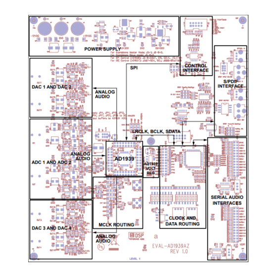
FUNCTIONAL BLOCK DIAGRAM
POWER SUPPLY
DAC 1 AND DAC 2
ANALOG
AUDIO
ANALOG
AUDIO
ADC 1 AND ADC 2
MCLK ROUTING
DAC 3 AND DAC 4
ANALOG
AUDIO
Pb
Evaluation Board User Guide
through an SPI or I
board, EVAL-ADUSB2EBZ (also called USBi), connects to a PC
USB port and provides I
board through a ribbon cable. A graphical user interface (GUI)
program is provided for easy programming of the chip in a
Microsoft® Windows® PC environment. The evaluation board
allows demonstration and performance testing of most
AD1937/AD1939 features, including four ADCs and eight
DACs, as well as the digital audio ports.
Additional analog circuitry (ADC input filters, DAC output
filter/buffer) and digital interfaces such as S/PDIF are provided
to ease product evaluation.
All analog audio interfaces are accessible with stereo audio,
3.5 mm TRS connectors.
CONTROL
SPI
INTERFACE
LRCLK, BCLK, SDATA
AD1939
AD1939
VOLT
REG
CLOCK AND
DATA ROUTING
a
Figure 1.
Rev. 0 | Page 1 of 32
C interface. A small external interface
2
C and SPI access to the evaluation
2
S/PDIF
INTERFACE
SERIAL AUDIO
INTERFACES
UG-040
Advertisement
Table of Contents

Subscribe to Our Youtube Channel
Related Manuals for Analog Devices EVAL-AD1937AZ


Summary of Contents for Analog Devices EVAL-AD1937AZ
-
Page 1: Eval-Ad1937Az/Eval-Ad1939Az Package Contents
One Technology Way • P.O. Box 9106 • Norwood, MA 02062-9106, U.S.A. • Tel: 781.329.4700 • Fax: 781.461.3113 • www.analog.com Evaluating the AD1937/AD1939 Four ADC/Eight DAC with PLL 192 kHz, 24-Bit Codec EVAL-AD1937AZ/EVAL-AD1939AZ PACKAGE through an SPI or I C interface. A small external interface... -
Page 2: Table Of Contents
UG-040 Evaluation Board User Guide TABLE OF CONTENTS EVAL-AD1937AZ/EVAL-AD1939AZ Package Contents ... 1 Powering the Board ...............4 Other Supporting Documentation ..........1 Setting Up the Master Clock (MCLK) ........4 Evaluation Board Overview ............1 Configuring the PLL Filter ............5 Functional Block Diagram .............. 1 Connecting Audio Cables ............6... -
Page 3: Setting Up The Evaluation Board
Copy the .xml file for the AD1937/AD1939 from the board passes audio from the S/PDIF port to all four stereo extraction folder into the C:\Program Files\Analog Devices outputs and from Stereo IN1 to the S/PDIF output ports. IN2 Inc\AutomatedRegWin folder, if it does not appear in the can be selected by changing S3, Position 8, to on. -
Page 4: Powering The Board
UG-040 Evaluation Board User Guide You can now open the Automated Register Window Builder SETTING UP THE MASTER CLOCK (MCLK) application and load the file for the part onto your evaluation The AD1937/AD1939 evaluation board has a series of jumpers board. -
Page 5: Configuring The Pll Filter
Evaluation Board User Guide UG-040 193X_MCLKI 193X_MCLKI DISABLE DISABLE JP20 JP18 JP20 JP18 C147 C147 MCLKO MCLKO XTAL XTAL JP19 JP19 1938_MCLKI 1938_MCLKI JP22 JP22 R160 R160 C158 C158 JP23 JP23 193X_MCLKO 193X_MCLKO CPLD CPLD R167 R167 JP25 JP25 HDR2 HDR2 R169 R169... -
Page 6: Connecting Audio Cables
UG-040 Evaluation Board User Guide PLL SELECT C120 TP26 IN1L+ IN1L R129 IN1L– C125 TP28 TP25 R138 JP15 C131 VREF SELECT Figure 14. MCLK Loop Filter Selected TP30 PLL SELECT IN1R TP32 C120 IN1R+ IN1R– TP34 R129 C125 R107 R106 R138 JP15 C131... - Page 7 Evaluation Board User Guide UG-040 For the full flexibility of the AD1937/AD1939, the part can be In this default configuration, the DAC audio path routes the put in SPI/I C control mode and programmed with the S/PDIF audio signal to all four stereo AD1937/AD1939 DSDATA Automated Register Window Builder application (see Figure 4 inputs simultaneously.
-
Page 8: Rotary And Dip Switch Settings
UG-040 Evaluation Board User Guide ROTARY AND DIP SWITCH SETTINGS Figure 17. Settings Chart 1 Rev. 0 | Page 8 of 32... - Page 9 Evaluation Board User Guide UG-040 Figure 18. Settings Chart 2 Rev. 0 | Page 9 of 32...
-
Page 10: Schematics And Artwork
UG-040 Evaluation Board User Guide SCHEMATICS AND ARTWORK Figure 19. Board Schematics, Page 1—ADC Buffer Circuits Rev. 0 | Page 10 of 32... - Page 11 Evaluation Board User Guide UG-040 Figure 20. Board Schematics, Page 2—Serial Digital Audio Interface Headers with MCLK Direction Switching Rev. 0 | Page 11 of 32...
- Page 12 UG-040 Evaluation Board User Guide Figure 21. Board Schematics, Page 3—S/PDIF Receive and Transmit Interfaces Rev. 0 | Page 12 of 32...
- Page 13 Evaluation Board User Guide UG-040 Figure 22. Board Schematics, Page 4—Serial Digital Audio Routing and Control CPLD Rev. 0 | Page 13 of 32...
- Page 14 UG-040 Evaluation Board User Guide Figure 23. Board Schematics, Page 5—AD1937/AD1939 with MCLK Selection Jumpers Rev. 0 | Page 14 of 32...
- Page 15 Evaluation Board User Guide UG-040 Figure 24. Board Schematics, Page 6—Daughter Card Interface, Useful as Test Points Rev. 0 | Page 15 of 32...
- Page 16 UG-040 Evaluation Board User Guide Figure 25. Board Schematics, Page 7—DAC Buffer Circuits Rev. 0 | Page 16 of 32...
- Page 17 Evaluation Board User Guide UG-040 Figure 26. Board Schematics, Page 8—SPI and I C Control Interface Rev. 0 | Page 17 of 32...
- Page 18 UG-040 Evaluation Board User Guide Figure 27. Board Schematics, Page 9—Power Supply Rev. 0 | Page 18 of 32...
- Page 19 Evaluation Board User Guide UG-040 Figure 28. Top Assembly Layer Rev. 0 | Page 19 of 32...
- Page 20 UG-040 Evaluation Board User Guide Figure 29. Bottom Assembly Layer Rev. 0 | Page 20 of 32...
-
Page 21: Cpld Code
Evaluation Board User Guide UG-040 CPLD CODE MODULE IF_Logic TITLE 'AD1939 EVB Input Interface Logic' //=================================================================================== FILE: AD1939_pld_revE.abl REVISION DATE: 04-16-09 (rev-E) REVISION: DESCRIPTION: //=================================================================================== LIBRARY 'MACH'; "INPUTS ---------------------------------------------------------------------------- // AD1939 CODEC pins DSDATA1,DSDATA2 pin 86, 87 istype 'com'; DSDATA3,DSDATA4 pin 91, 92 istype 'com';... - Page 22 UG-040 Evaluation Board User Guide BCLK_8416 pin 60 istype 'com'; LRCLK_8416 pin 59 istype 'com'; SOMS_RX,SFSEL1_RX,SFSEL0_RX,RMCKF_RX pin 66,67,64,65 istype 'com'; // S/PDIF Tx CS8404 pins SDATA_8406 pin 50 istype 'com'; BCLK_8406,LRCLK_8406 pin 53, 54 istype 'com'; MCLK_8406 pin 49 istype 'com';...
- Page 23 Evaluation Board User Guide UG-040 //================================================================================ "MACROS // Switch S3, DIP POSITIONS 6 AND 7 ADC_HDR_NORMAL = ( MODE22 & MODE23); ADC_HDR_DATA2_DATA1 = ( MODE22 & !MODE23); ADC_HDR_TDM = (!MODE22 & MODE23); ADC_HDR_AUX = (!MODE22 & !MODE23); S/PDIF_OUT_MUX = MODE24; // Hex Switch S4 // S4 position 0, DAC_RX_ALL...
- Page 24 UG-040 Evaluation Board User Guide // S4 position B, DAC_DUAL_TDM ( !MODE14 & MODE13 & !MODE12 & !MODE11); // S4 position C, DAC_HDR1_AUX ( !MODE14 & !MODE13 & MODE12 & MODE11); // S4 position D, ( !MODE14 & !MODE13 & MODE12 &...
- Page 25 Evaluation Board User Guide UG-040 M3_8414 = 0; // CS8404 Tx interface mode select APMS_TX = 0; // Tx serial port is always slave in this application SFMT1_TX = 0; // Tx data format is I2S always SFMT0_TX = 1; M0_8404 = 0;...
- Page 26 UG-040 Evaluation Board User Guide HDR1_DSDATA4.oe = (DAC_DUAL_TDM # ADC_HDR_AUX # DAC_HDR1_AUX); HDR1_ASDATA2.oe = (!ADC_HDR_TDM); DBCLK = I_DBCLK; DLRCLK = I_DLRCLK; ABCLK = I_ABCLK; ALRCLK = I_ALRCLK; DSDATA1 = (HDR1_DSDATA1 & (DAC_HDR1_ALL # DAC_HDR1_IND # DAC_RX_2 # DAC_RX_3 # DAC_RX_4 # DAC_HDR1_TDM # DAC_DUAL_TDM # ADC_HDR_AUX)) # (SDATA_8416 &...
-
Page 27: Ordering Information
Evaluation Board User Guide UG-040 ORDERING INFORMATION BILL OF MATERIALS Table 1. Designator Description Manufacturer Part Number C85, C90 to C94, C101 to C103, Multilayer ceramic capacitor,16 V, X7R Panasonic EC ECJ-0EX1C104K C107, C108, C110, C115, C116, (0402) C121, C127, C132, C134 C1, C2, C5, C7 to C10, C20, C21, Multilayer ceramic capacitor, 50 V, X7R Panasonic EC... - Page 28 UG-040 Evaluation Board User Guide Designator Description Manufacturer Part Number R56, R57, R65, R66, R88, R89, R140, Chip resistor, 24.9 Ω, 1%, 100 mW, thick film Rohm MCR03EZPFX24R9 R154, R179, R183, R213, R216, (0603) R228 to R231 C24, C25, C31, C34, C44, C45, C53, Multilayer ceramic capacitor, 100 V, NP0 Murata ENA GRM1885C2A301JA01D...
- Page 29 C57, C165, C173, C182, C186, (0603) C187, C192, C199, C202 Crystal, 12.288 MHz, SMT, 10 pF Abracon Corp ABM3B-12.288MHZ-10- 1-U-T Four ADC/eight DAC with PLL, 192 kHz Analog Devices AD1939YSTZ Microprocessor voltage supervisor Analog Devices ADM811RARTZ Voltage regulator, low dropout Analog Devices ADP3303ARZ-3.3...
- Page 30 UG-040 Evaluation Board User Guide Designator Description Manufacturer Part Number 110 Ω AES/EBU transformer Scientific SC937-02 Conversion U18, U22 Buffer, three-state single gate Texas Instruments SN74LVC1G125DRLR Octal, three-state buffer/driver Texas Instruments SN74LVC541ADBR SW2, SW3 SPDT slide switch, PC mount E-Switch EG1218 S2, S3 8-position, SPST SMD switch, flush,...
- Page 31 Evaluation Board User Guide UG-040 NOTES Rev. 0 | Page 31 of 32...
- Page 32 By using the evaluation board discussed herein (together with any tools, components documentation or support materials, the “Evaluation Board”), you are agreeing to be bound by the terms and conditions set forth below (“Agreement”) unless you have purchased the Evaluation Board, in which case the Analog Devices Standard Terms and Conditions of Sale shall govern. Do not use the Evaluation Board until you have read and agreed to the Agreement.
- Page 33 Mouser Electronics Authorized Distributor Click to View Pricing, Inventory, Delivery & Lifecycle Information: Analog Devices Inc. EVAL-AD1937AZ EVAL-AD1939AZ...
Need help?
Do you have a question about the EVAL-AD1937AZ and is the answer not in the manual?
Questions and answers