Table of Contents
Advertisement
Quick Links
FEATURES
Fully featured evaluation board for the ADMV8513
►
On-board system demonstration platform (SDP-S) connector for
►
the SPI
Evaluation using on-board LDO regulators powered by the USB
►
ACE
software interface for SPI control
►
EQUIPMENT NEEDED
Network analyzer
►
®
Windows
PC
►
USB cable
►
EVAL-SDP-CS1Z (SDP-S) controller board
►
DOCUMENTS NEEDED
ADMV8513 data sheet
►
SOFTWARE NEEDED
ACE software
►
GENERAL DESCRIPTION
The ADMV8513-EVALZ is available for evaluating the ADMV8513
digitally tunable, band-pass filter (BPF). The ADMV8513-EVALZ
incorporates the ADMV8513 chip, as well as a negative voltage
generator, low dropout (LDO) regulators, and an interface to the
EVAL-SDP-CS1Z (SDP-S) system demonstration platform (SDP) to
allow simple and efficient evaluation. The negative voltage genera-
tor and LDO regulators allow the ADMV8513 to be powered by
either the 5 V USB supply voltage from the PC via the SDP-S or by
using two external power supplies.
The ADMV8513 is an IC that features a digitally selectable frequen-
cy of operation. The chip can be programmed using a 4-wire serial
peripheral interface (SPI), and the SDP-S controller allows the user
to interface with the SPI of the ADMV8513 through the Analog
Devices, Inc.,
Analysis, Control Evaluation
For full details on the ADMV8513, see the ADMV8513 data sheet,
which must be consulted in conjunction with this user guide when
using the ADMV8513-EVALZ.
PLEASE SEE THE LAST PAGE FOR AN IMPORTANT
WARNING AND LEGAL TERMS AND CONDITIONS.
Arrow.com.
Downloaded from
Evaluating the ADMV8513 520 MHz to 1300 MHz,
Digitally Tunable, Band-Pass Filter
(ACE) software.
User Guide | EVAL-ADMV8513
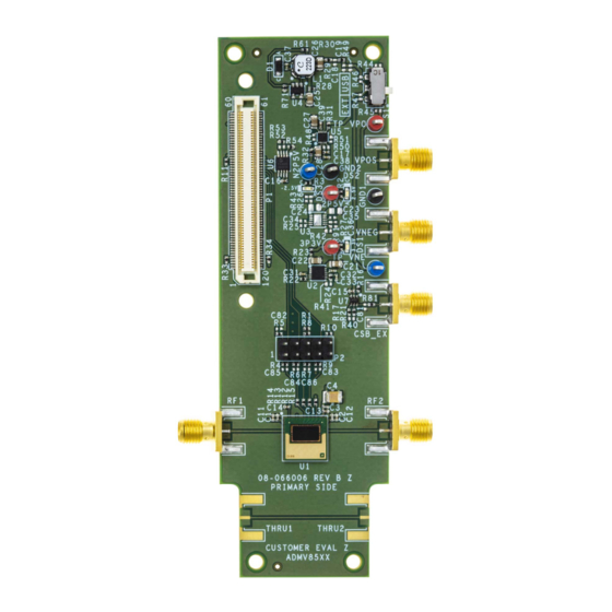
EVALUATION BOARD PHOTOGRAPH
Figure 1. ADMV8513-EVALZ Evaluation Board Photograph
UG-2045
Rev. 0 | 1 of 17
Advertisement
Table of Contents

Related Manuals for Analog Devices ADMV8513-EVALZ


Summary of Contents for Analog Devices ADMV8513-EVALZ
-
Page 1: Features
ACE software ► GENERAL DESCRIPTION The ADMV8513-EVALZ is available for evaluating the ADMV8513 digitally tunable, band-pass filter (BPF). The ADMV8513-EVALZ incorporates the ADMV8513 chip, as well as a negative voltage generator, low dropout (LDO) regulators, and an interface to the EVAL-SDP-CS1Z (SDP-S) system demonstration platform (SDP) to allow simple and efficient evaluation. -
Page 2: Table Of Contents
User Guide EVAL-ADMV8513 TABLE OF CONTENTS Features..............1 ADMV8513-EVALZ Quick Start......10 Equipment Needed..........1 Network Analyzer Settings....... 10 Documents Needed..........1 CSV Files............10 Software Needed...........1 Automatic Chip Reset........11 General Description..........1 Manual Chip Reset........... 11 Evaluation Board Photograph........1 Loss of Board Communication......11 Evaluation Board Hardware........3... -
Page 3: Evaluation Board Hardware
Figure 2 shows an example lab bench setup for the ADMV8513- To power the ADMV8513-EVALZ using the 5 V USB supply, slide EVALZ. To observe the filter response from the ADMV8513-EVALZ, the S1 switch to select USB (as shown in... -
Page 4: Evaluation Board Software
User Guide EVAL-ADMV8513 EVALUATION BOARD SOFTWARE INSTALLING THE ACE SOFTWARE, ADMV8513 PLUG-INS, AND DRIVERS The ADMV8513-EVALZ uses the Analog Devices Analysis|Con- trol|Evaluation (ACE) software. For instructions on how to install and use the ACE software, go to www.analog.com/ACE. If the ACE software is already installed on the PC, ensure that the installed ACE software is the latest version, as listed on the ACE software page. -
Page 5: Plug-In Overview
EVAL-ADMV8513 EVALUATION BOARD SOFTWARE PLUG-IN OVERVIEW When the ADMV8513-EVALZ is connected to the PC, the ADMV8513 Board appears in the Attached Hardware section of the Start tab. Double-click the ADMV8513 Board plug-in to open two tabs, which are the ADMV8513 Board plug-in view (see... -
Page 6: Plug-In Details
Label Function Use the CONFIGURATION section to initialize the ADMV8513-EVALZ. Load Settings from CSV: click the … button to select which .csv file to load into the CONFIGURATION section. Check to Load Settings: once a file is selected, select this check box to load the .csv file contents into the CONFIGURATION section. Note that a check mark does not appear when the check box is selected. - Page 7 CSB_AUX: this pin is only available in SFL mode. Selecting the check box brings the CSB_AUX pin high, which advances the internal state machine pointer to the next LUT. If an external waveform generator is connected to the CSB_EXT port on the ADMV8513-EVALZ, the CSB_AUX pin has no effect, and the CSB_EXT port takes precedence.
- Page 8 User Guide EVAL-ADMV8513 EVALUATION BOARD SOFTWARE Figure 8. ADMV8513 Memory Map in the ACE Software Figure 9. Interpolation Coefficients Subdiagram in the ACE Software analog.com Rev. 0 | 8 of 17 Arrow.com. Downloaded from...
- Page 9 User Guide EVAL-ADMV8513 EVALUATION BOARD SOFTWARE Figure 10. Coefficient Calibration Subdiagram in the ACE Software analog.com Rev. 0 | 9 of 17 Arrow.com. Downloaded from...
-
Page 10: Performing Evaluation
1. If the Modify button is visible, click to allow changes. after completing Step 3 or Step 4. 2. Click Restore Software Defaults to zero out the CONFIGURA- 3. On the ADMV8513-EVALZ, slide the S1 switch to select USB TION section. (as shown in... -
Page 11: Automatic Chip Reset
PERFORMING EVALUATION AUTOMATIC CHIP RESET REGULATOR BYPASS If a reset of the ADMV8513 chip is required on the ADMV8513- The ADMV8513-EVALZ has a negative voltage generator and three EVALZ, click Reset Chip (see Figure 7, Label J3, and Table 1 LDO regulators on board that allow the user to operate the device for additional information). -
Page 12: Evaluation Board Schematics And Artwork
User Guide EVAL-ADMV8513 EVALUATION BOARD SCHEMATICS AND ARTWORK ADMV8513-EVALZ Figure 12. ADMV8513-EVALZ Schematic, Page 1 analog.com Rev. 0 | 12 of 17 Arrow.com. Downloaded from... - Page 13 User Guide EVAL-ADMV8513 EVALUATION BOARD SCHEMATICS AND ARTWORK Figure 13. ADMV8513-EVALZ Schematic, Page 2 analog.com Rev. 0 | 13 of 17 Arrow.com. Downloaded from...
- Page 14 User Guide EVAL-ADMV8513 EVALUATION BOARD SCHEMATICS AND ARTWORK Figure 15. ADMV8513-EVALZ Layer 2 Figure 14. ADMV8513-EVALZ Layer 1 analog.com Rev. 0 | 14 of 17 Arrow.com. Downloaded from...
- Page 15 User Guide EVAL-ADMV8513 EVALUATION BOARD SCHEMATICS AND ARTWORK Figure 16. ADMV8513-EVALZ Layer 3 Figure 17. ADMV8513-EVALZ Layer 4 analog.com Rev. 0 | 15 of 17 Arrow.com. Downloaded from...
-
Page 16: Ordering Information
User Guide EVAL-ADMV8513 ORDERING INFORMATION BILL OF MATERIALS Table 2. ADMV8513-EVALZ Quantity Reference Designator Description Manufacturer Part Number 2P5V, 3P3V, TP_VPOS Test points, red Components Corporation TP-104-01-02 GND1, GND2 Test points, black Components Corporation TP-104-01-00 N2P5V, TP_VNEG Test points, blue... -
Page 17: Notes
Evaluation Board until you have read and agreed to the Agreement. Your use of the Evaluation Board shall signify your acceptance of the Agreement. This Agreement is made by and between you (“Customer”) and Analog Devices, Inc. (“ADI”), with its principal place of business at Subject to the terms and conditions of the Agreement, ADI hereby grants to Customer a free, limited, personal, temporary, non-exclusive, non-sublicensable, non-transferable license to use the Evaluation Board FOR EVALUATION PURPOSES ONLY.
Need help?
Do you have a question about the ADMV8513-EVALZ and is the answer not in the manual?
Questions and answers