Table of Contents
Advertisement
Quick Links
One Technology Way • P.O. Box 9106 • Norwood, MA 02062-9106, U.S.A. • Tel: 781.329.4700 • Fax: 781.461.3113 • www.analog.com
Evaluating the
FEATURES
Debug and programming capability of the
Evaluation capability with electrochemical gas sensors
ADT7420
±0.25°C accurate temperature sensor via I
MicroUSB power option and connection to PC
EQUIPMENT NEEDED
PC running Windows® 7 or later
Electrochemical gas sensor or resistor star network
DOCUMENTS NEEDED
ADuCM355 hardware reference manual
ADuCM355
data sheet
SOFTWARE NEEDED
IAR Embedded Workbench or Keil μVision
ADuCM355 GitHub Repository
Terminal program such as RealTerm
PLEASE SEE THE LAST PAGE FOR AN IMPORTANT
WARNING AND LEGAL TERMS AND CONDITIONS.
EVAL-ADuCM355QSPZ
ADuCM355
Precision Analog Microcontroller
with Chemical Sensor Interface
ADuCM355
2
C
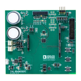
EVALUATION BOARD PHOTOGRAPH
Figure 1.
Rev. A | Page 1 of 24
GENERAL DESCRIPTION
The
ADuCM355
on-chip system provides the features needed
to bias and to measure a range of different electrochemical
sensors. The EVAL-ADuCM355QSPZ allows users to evaluate
the performance of the
ADuCM355
range of different electrochemical techniques, including
chronoamperometry, voltammetry, and electrochemical
impedance spectroscopy (EIS).
Complete specifications for the
ADuCM355
data sheet, which must be consulted in conjunction
with this user guide when using the EVAL-ADuCM355QSPZ.
Evaluation Board
UG-1308
when implementing a
ADuCM355
are available in the
Advertisement
Table of Contents

Subscribe to Our Youtube Channel
Related Manuals for Analog Devices EVAL-ADuCM355QSPZ


Summary of Contents for Analog Devices EVAL-ADuCM355QSPZ
-
Page 1: Features
Complete specifications for the ADuCM355 are available in the DOCUMENTS NEEDED ADuCM355 data sheet, which must be consulted in conjunction with this user guide when using the EVAL-ADuCM355QSPZ. ADuCM355 hardware reference manual ADuCM355 data sheet SOFTWARE NEEDED IAR Embedded Workbench or Keil μVision... -
Page 2: Table Of Contents
UG-1308 EVAL-ADuCM355QSPZ Evaluation Board TABLE OF CONTENTS Features ....................1 Running a GPIO Example in IAR Embedded Workbench ..8 Equipment Needed ................1 Running a GPIO Example in Keil μVision ......11 Documents Needed ................1 Application Examples .............. - Page 3 EVAL-ADuCM355QSPZ Evaluation Board UG-1308 Changes to Figure 33 ..............19 2/2019—Revision 0: Initial Version Moved Figure 26 to Figure 28 ............19 Deleted Figure 36 ................19 Moved Low Power TIA0/TIA1 Gain Resistor Calibration Section and Figure 36 ..............20 Changes to Low Power TIA0/TIA1 Gain Resistor Calibration Section .................
-
Page 4: Power Configurations
MicroUSB DIRECT POWER VIA P4 AND ADP7158 EVAL-ADuCM355QSPZ. The different power options include LDO REGULATOR the following: To power the EVAL-ADuCM355QSPZ via the P4 microUSB Power via a microUSB connector, P4, and the on- connector, take the following steps: board... -
Page 5: Section, Jumper Setup With Power Via Usb Section, Figure
EVAL-ADuCM355QSPZ Evaluation Board UG-1308 3V3VOUT 5VUSB 0.1µF 0.1µF DGND 3V3VOUT VCCIO 0.1µF 3V3VOUT RESET 3V3OUT TEST OSCO P0.11_SIN OSCI DGND P0.10_SOUT JP46 JP45 M20-9990245 DGND CBUS0 CBUS1 CBUS2 USBD– USBDM CBUS3 USBD+ USBDP CBUS4 DGND AGND FT232RQ DGND Figure 3. JP45 and JP46 Connect the... -
Page 6: Direct 3.3 V Power Via The Avdd And Dvdd Connectors
(I ), connect 3.3 V directly to the AVDD and DVDD connectors. To power the EVAL-ADuCM355QSPZ in this case, apply a 3.3 V supply directly to Pin 1 on the AVDD connector and to Pin 1 on the DVDD connector. -
Page 7: Connecting An Electrochemical Sensor
EVAL-ADuCM355QSPZ Evaluation Board UG-1308 CONNECTING AN ELECTROCHEMICAL SENSOR ADuCM355 has two measurement channels (CH0 and CH1) for electrochemical sensors. A 2-lead, 3-lead, or 4-lead sensor can be connected to either CH0 or CH1. Figure 7 shows an electrochemical sensor connected to CH1. -
Page 8: Getting Started With The Tool Chain
UG-1308 EVAL-ADuCM355QSPZ Evaluation Board GETTING STARTED WITH THE TOOL CHAIN DOWNLOADING THE INTEGRATED RUNNING A GPIO EXAMPLE IN IAR EMBEDDED DEVELOPMENT ENVIRONMENT (IDE) WORKBENCH ADUCM355 firmware examples use either the IAR ADUCM355 CMSIS pack is not supported for IAR Embedded Workbench® or Keil μVision® IDEs to run the Embedded Workbench. -
Page 9: Replaced Figure 9
EVAL-ADuCM355QSPZ Evaluation Board UG-1308 Figure 9. IAR Embedded Workbench Rev. A | Page 9 of 24... -
Page 10: Changes To Compiling And Running Firmware Section And Figure 11 Caption
EVAL-ADuCM355QSPZ is powered on and the J-Link To compile and run the ADuCM355 firmware, take the debugger is connected to P3 on the EVAL-ADuCM355QSPZ, following steps: then click Download and Debug to load the firmware to In the IAR Embedded Workbench window, navigate to ADuCM355 and launch the debugger (see Figure 12). -
Page 11: Replaced Figure 14
EVAL-ADuCM355QSPZ Evaluation Board UG-1308 Figure 14. Debug Interface RUNNING A GPIO EXAMPLE IN KEIL μVISION To download the ADuCM355 device family pack for Keil μVision, visit the Keil website and search for MDK5 software packs. Save the .pack file to a directory on the PC. Double click the file to install the pack. -
Page 12: Added Figure 17 To Figure 19
Keil μVision. To compile and build the project, click the Rebuild icon shown in the blue circle in Figure 19. To load the code onto the ADuCM355, ensure that the EVAL-ADuCM355QSPZ is powered on and the mIDAS-Link debugger is connected, and then click the load icon shown in the red circle in Figure 19. -
Page 13: Application Examples
EVAL-ADuCM355QSPZ Evaluation Board UG-1308 APPLICATION EXAMPLES This section describes how to use the ADuCM355 application contains the low level device configuration for the cyclic examples that are part of the ADuCM355 software development voltammetry measurement. kit (SDK). The ADuCM355 is a dual-die device that has a Figure 21 shows the AD5940RampStructInit (void) function Cortex-M3 digital die and an analog front-end (AFE) die. -
Page 14: Eis Example
IDE. For the purpose of this initial test, a dummy electrochemical cell is used. Connect three 1 kΩ resistors in a star network, and connect the star network to the CE0, RE0, and SE0 pins on P5 of the EVAL-ADuCM355QSPZ (see Figure 22). Rev. A | Page 14 of 24... -
Page 15: Dc Current Example
The output is the current measured through the SE0 pin program. Compile and build the project and load the code onto on P5 of the EVAL-ADuCM355QSPZ (see Figure 29). the ADuCM355. Start the code execution and save the UART data to a .csv file for processing. -
Page 16: 4-Lead Electrochemical Sensor Example
UG-1308 EVAL-ADuCM355QSPZ Evaluation Board 4-LEAD ELECTROCHEMICAL SENSOR EXAMPLE Figure 30 shows the configurable parameters located in the AD5940Main.c file. Modify the value of the correct Many electrochemical sensors come in 4-lead packages that have a LpTiaRtiaSel parameter for each channel based on the counter, a reference, and two sensing electrodes. -
Page 17: Connecting An External Gain Resistor Across The High Speed Tia
The EVAL-ADuCM355QSPZ supports the connection of an external transimpedance amplifier resistor (R ) across the The M355_AfeWdt code example project in the examples folder shows how to configure the windowed watchdog mode. -
Page 18: Aducm355 System Calibration
UG-1308 EVAL-ADuCM355QSPZ Evaluation Board ADUCM355 SYSTEM CALIBRATION Because of the complexity of the ADuCM355 and the large If the high speed TIA is uncalibrated for the selected gain resistor number of voltage and current measurement channels on the and the ADC programmable gain amplifier (PGA) setting, an error device, many calibration routines are implemented to ensure a is present when measuring an absolute input current. - Page 19 EVAL-ADuCM355QSPZ Evaluation Board UG-1308 P_NODE RCAL0 HSDAC EXCITATION EXTERNAL AMPLIFIER P_NODE N_NODE RCAL1 N_NODE CALIBRATION INPUT CURRENT 1.11V (HSTIACON[1:0] = 00b] HPTIA_P HPTIA_P HPTIA_N TIA2 HPTIA_N Figure 33. High Speed DAC, High Speed TIA, and Switch Matrix Settings for R...
-
Page 20: Low Power Tia0/Tia1 Gain Resistor Calibration
UG-1308 EVAL-ADuCM355QSPZ Evaluation Board LOW POWER TIA0/TIA1 GAIN RESISTOR resistor that is connected to the ADuCM355 RCAL0 pin and RCAL1 pin. The precision calibration current is routed CALIBRATION through either the low power TIA0 gain resistor or the low ADuCM355 contains two independent, low power power TIA1 gain resistor. - Page 21 EVAL-ADuCM355QSPZ Evaluation Board UG-1308 VBIAS0 VZERO0 SW12 SW13 VZERO0 LPDAC0 VBIAS0 HSTIA RCAL1 VZERO0 EXTERNAL N_NODE VBIAS0 P_NODE N_NODE P_NODE RCAL0 INPUT CALIBRATION CURRENT LPTIA0_P LPTIA0_N LPTIA0 LOAD LPTIA0_P LPRTIA0 LPTIA0_N Figure 37. High Speed TIA, Low Power TIA0, and Switch Matrix Settings for LPRTIA0 Resistor Calibration...
-
Page 22: Mass Erasing A Device Not Responding To Swd Commands
UG-1308 EVAL-ADuCM355QSPZ Evaluation Board MASS ERASING A DEVICE NOT RESPONDING TO SWD COMMANDS The SWD debug tools can only communicate with the To mass erase the user flash, take the following steps: microcontroller when the device is in active mode. -
Page 23: Ordering Information
EVAL-ADuCM355QSPZ Evaluation Board UG-1308 ORDERING INFORMATION To view the complete EVAL-ADuCM355QSPZ schematic, visit https://www.analog.com/media/en/technical-documentation/evaluation- documentation/EVAL-ADuCM355-RevBSchematic.pdf. To view the PCB layout, visit https://www.analog.com/media/en/technical-documentation/evaluation-documentation/EVAL- ADuCM355-EvalBrd_Layout.pdf. BILL OF MATERIALS Table 2. Name Value Part Description Manufacturer Part No. AVDD, DVDD 25.195.0253.0 Connector PCB terminal block 3.5 mm Wieland Electric 25.195.0253.0... - Page 24 By using the evaluation board discussed herein (together with any tools, components documentation or support materials, the “Evaluation Board”), you are agreeing to be bound by the terms and conditions set forth below (“Agreement”) unless you have purchased the Evaluation Board, in which case the Analog Devices Standard Terms and Conditions of Sale shall govern. Do not use the Evaluation Board until you have read and agreed to the Agreement.
Need help?
Do you have a question about the EVAL-ADuCM355QSPZ and is the answer not in the manual?
Questions and answers