Table of Contents
Advertisement
Quick Links
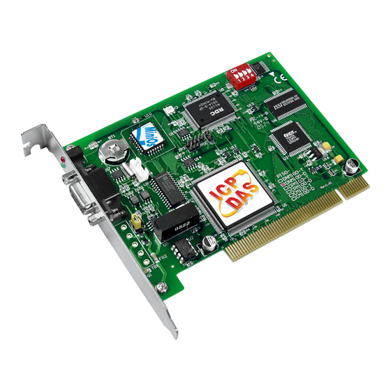
DeviceNet Master PCI Board
Warranty
All products manufactured by ICP DAS are warranted
against defective materials for a period of one year from the
date of delivery to the original purchaser.
Warning
ICP DAS assumes no liability for damages consequent
to the use of this product. ICP DAS reserves the right to
change this manual at any time without notice. The
information furnished by ICP DAS is believed to be accurate
and reliable. However, no responsibility is assumed by ICP
DAS for its use, or for any infringements of patents or other
rights of third parties resulting from its use.
Copyright
Copyright 2007 by ICP DAS Co., LTD. All rights
reserved worldwide.
Trademark
The names used for identification only may be
registered trademarks of their respective companies.
PISO-DNM100 DeviceNet Master API functions User's Manual (Ver: 1.0)
PISO-DNM100-D/T
User's Manual
2008/02/25
1
Advertisement
Table of Contents

Related Manuals for ICP DAS USA PISO-DNM100-D


Summary of Contents for ICP DAS USA PISO-DNM100-D
- Page 1 PISO-DNM100-D/T DeviceNet Master PCI Board User’s Manual Warranty All products manufactured by ICP DAS are warranted against defective materials for a period of one year from the date of delivery to the original purchaser. Warning ICP DAS assumes no liability for damages consequent to the use of this product.
-
Page 2: Table Of Contents
Contents G ENERAL INFORMATION .................5 1 .1 D ..................5 EVICE NTRODUCTION 1 .2 D ..................7 EVICE PPLICATIONS 1 .3 PISO-DNM100 A .................8 RCHITECTURE 1 .4 D ..............9 EVICE ASTER HARACTERISTICS 1 .5 PISO-DNM100 F ............12 IRMWARE HARACTERISTICS 1 .6 F ........................14 EATURES 1 .7 S... - Page 3 4 .2 F ..................48 UNCTION ETURN 4 .3 F UCMM A ........61 IAGRAM FOR CHECK RCHITECTURE 4 .4 F ..................62 UNCTION ESCRIPTION 4 .4.1 DNM100_GetBoardInf .................62 4 .4.2 DNM100_TotalDNM100Board ..............63 4 .4.3 DNM100_ActiveBoard .................64 4 .4.4 DNM100_CloseBoard ..................65 4 .4.5 DNM100_GetDLLVersion ................66 4 .4.6 DNM100_GetFirmwareVersion ..............67...
- Page 4 4 .4.36 DNM100_GetDeviceCOSInfo ..............97 4 .4.37 DNM100_GetDeviceCyclicInfo ..............98 4 .4.38 DNM100_AutoScanDevice ................99 4 .4.39 DNM100_GetScanList ................100 4 .4.40 DNM100_ConfigPoll ................101 4 .4.41 DNM100_UpdatePollConfig ..............102 4 .4.42 DNM100_ReadPollInputData ..............103 4 .4.43 DNM100_WritePollOutputData ...............104 4 .4.44 DNM100_GetPollStatus ................105 4 .4.45 DNM100_GetPollResult ................106 4 .4.46 DNM100_CheckPollConnectionStatus ............107 4 .4.47 DNM100_ConfigBitStrobe...
-
Page 5: General Information
1. General Information 1.1 DeviceNet Introduction C AN o ntroller r ea e twork) is a serial communication protocol, which efficiently supports distributed real-time control with a very high level of security. It is an especially suited for networking "intelligent" devices as well as sensors and actuators within a system or sub-system. - Page 6 DeviceNet is a cost effective solution to one kind application of control c\area network. It reduces the connection wires between devices and provides rapid troubleshooting rejection function. The transfer rate can be up to 500Kbps within 100 meters. The transfer distance can be up to 500 meters in 125Kbps (See Table 1.1).
-
Page 7: Devicenet Applications
1.2 DeviceNet Applications DeviceNet is the standardized network application layer optimized for factory automation. It is mainly used in low- and mid-volume automation systems. Some users have also implemented DeviceNet for machine control systems. The main DeviceNet application fields include the following application area (For more information, please refer to w ww.odva.org H H H T U... -
Page 8: Piso-Dnm100 Architecture
1.3 PISO-DNM100 Architecture The PISO-DNM100 provides users to establish DeviceNet network rapidly by Master/Slave connection model. The PISO-DNM100 is a high-performance DeviceNet master board with one CPU inside. This architecture of the PISO- DNM100 almost doesn’t cost CPU resource and really increases the work efficiency on DeviceNet network. -
Page 9: Devicenet Master Characteristics
1.4 DeviceNet Master Characteristics Using the API functions, users don’t need to take care of the detail of the DeviceNet protocol. It can reduce the complexity of user’s DeviceNet Master Software. The firmware mainly supports the Predefined Master-Slave Connection Set and UCMM functions to allow users to merge third party’s DeviceNet devices into the DeviceNet network. - Page 10 The DeviceNet protocol firmware provides the DeviceNet Master mechanism to communicate with slave devices by the Predefined Master/Slave Connection Set and UCMM Connection Set. In the DeviceNet communication protocol can be clarify as two forms: One is the Explicit Message and others are I/O Messages.
- Page 11 1. Add device into firmware You should provide the slave device’s MAC ID to add into firmware by using API function. 2. Configure connection You can check the slave device’s I/O connection type and the I/O data length. When configuring the I/O connection, you should provide these parameters.
-
Page 12: Piso-Dnm100 Firmware Characteristics
1.5 PISO-DNM100 Firmware Characteristics The PISO-DNM100 is a high-performance DeviceNet master board. The firmware inside the board implements DeviceNet protocol automatically when the board is active. The firmware always listens to the bus and receives the message at the same time. It works as shown in Figure 1.6. Figure 1.6 Message Router PISO-DNM100 DeviceNet Master API functions User’s Manual (Ver: 1.0) 2008/02/25... - Page 13 The PISO-DNM100 firmware has a “ScanList” to store the remote slave devices information. After power off, the information still exists in the EEPROM. When the users turn on the PC next time, the “ScanList” will be loaded from EEPROM. The users can easily use the DLL functions to configure it, including adding devices or removing devices.
-
Page 14: Features
1.6 Features H ardware Features PCI BUS interface. Driver supported for Windows 98/ME/NT/2000/XP. 186 compatible CPU with DeviceNet firmware inside. 8K bytes DPRAM inside. One CAN communication port. Compatible with CAN specification 2.0 parts A and B. Jumper select 120Ω terminator resistor for each port. 2 indicating LED (one for green and another for red). -
Page 15: Specifications
1.7 Specifications CAN controller: Phillips SJA1000T. CAN transceiver: Phillips 82C250/251. Signal support: CAN_H, CAN_L. CAN controller frequency :16 MHz Connector: 5-pin screw terminal connector or 9-pin D-sub male connector. Isolation voltage: 2500Vrms on CAN bus. 186 compactable CPU 8K bytes DPRAM (1K bytes for system) 512 K bytes Flash memory (128K bytes for system) 512K bytes SRAM RTC (real time clock) inside... -
Page 16: Block Diagram
1.8 Block Diagram The figure 1.8 shows the block diagram of the PISO-DNM100 board. 1. DPRAM (Dual Port RAM) : The DPRAM is the memory buffer which provides the communication channel between PC and PISO-DNM100. 2. EEPROM : The EEPROM stores the configuration information. After restarting the PC, the configuration data will be loaded form the EEPROM automatically. -
Page 17: Product Check List
1.9 Product Check List In addition to this manual, the package includes the following items: PISO-DNM100 card; Software CD ROM; User manual; Quick Start manual; Release Note It is recommended that users should read the release note first. All of the important information needed will be provided in the release note as follows: Where you can find the software driver, utility and demo programs. -
Page 18: Hardware Configuration
Note: PISO-DNM100-T layout is similar with PISO-DNM100-D. The only difference is the position of CAN port connector. The positions of jumper or DIP switch are the same. Therefore, users can also refer to the PISO-DNM100-D layout to configure the jumper or DIP switch if they use PISO-DNM100-T. -
Page 19: Jumper Selection
Reset pin for download error. If users want to update firmware but the process is fail, users can enable this jumper to Enable Disable reset PISO-DNM100-D/T into download mode. None. None DIP switch is used to set the PISO- CM100 board No. Switch1 is for bit0, switch2 is for bit1 and so forth. -
Page 20: Connector Pin Assignment
2.3 Connector Pin Assignment The PISO-DNM100-T is equipped with one 5-pin screw terminal connector and the PISO-DNM100-D is equipped with one 9-pin D-sub male connector for wire connection of the CAN bus. The connector’s pin assignment is specified as follows: 2.3.1 5-pin screw terminal connector... -
Page 21: 9-Pin D-Sub Male Connector
2.3.2 9-pin D-sub male connector The 9-pin D-sub male connector of the CAN bus interface is shown in Figure 2.5 and the corresponding pin assignments are given in Table 2.3. CAN-L Shield CAN-H Figure2.5 9-pin D-sub male connector Pin No. Signal Description No use... -
Page 22: Wire Connection
2.3.3 Wire connection In order to minimize the reflection effects on the CAN bus line, the CAN bus line has to be terminated at both ends by two terminal resistances as in the following figure. According to the ISO 11898-2 spec, each terminal resistance is 120Ω... -
Page 23: Indicator Led
2.4 Indicator LED 2.4.1 G reen The [Green] LED indicates the firmware status in the PISO-DNM100. There are 3 situations in [Green] LED. (1). LED off: This indicates that there are some errors on the bus or in the firmware. The DeviceNet firmware is not running. (2). -
Page 24: Hardware Installation
2.1 and table 2.1. 3. Check JP3 status of PISO-DNM100-D/T. If necessary, enable it. 4. Find an empty PCI slot for your PISO-DNM100-D/T on the mother board of the personal computer. Plug the configured PISO-DNM100-D/T into this empty PCI slot. See figure 2.5. -
Page 25: Driver Installation And Software Application
3. Driver Installation and Software Application The DeviceNet DLL driver (DNM100.dll) collection of function calls for the PISO-DNM100 cards used in Windows 98/Me/NT/2000/XP systems. The application structure is presented in the following figure. The user’s DeviceNet application programs can be developed by the following designated tools: VB, Delphi and Borland C++ Builder…etc. -
Page 26: Driver Installation Of The Piso-Dnm100
3.1 Driver Installation of the PISO-DNM100 The software Installation for DeviceNet application is demonstrated as the following descriptions. After finishing the procedure, the driver, demos, manual and Utility can be in your PC. For the advance application, users can refer to the basic demo programs to develop the customized DeviceNet master application. - Page 27 Step 3: When the window is changing to the picture below, please move the mouse cursor on the “Master” item. Step 4: The DeviceNet master products will be shown in the window. Step 5: Click “install Toolkit for Windows 98, Me, NT, 2000, XP, which is based on the operation system you used”.
- Page 28 Step 8: Press “Next” button. The screen shoot is shown below. After reading the license, the users can accept it or not. If the users accept it, please select “I accept….” and press “Next” button. Step 9: After accepting the license, the next screen shoot is shown as follows. Users can edit your name and company name.
- Page 29 Step 11: The next screen shoot is shown as follows. Please press “Install” button. The setup process will start. Step 12: The setup process is running. The screen shoot is shown below. Step 13: Wait for the setup process finishing. The next screen shoot is shown below.
- Page 30 Step 14: The next screen shoot is shown as follows. Please restart your PC. Then the setup software would copy the related material to the indicated directory and register the driver on your computer. The driver target directory is different according to the different systems as follows. Windows NT/2000 –...
-
Page 31: Flow Diagram For Debugging
3.2 Flow Diagram for Debugging Before developing the DeviceNet applications, users should test to connect to the slave devices. When users have no idea to communicate with them, users can follow these steps shown in figure 3.2. The following functions can help users to get the DeviceNet information of the slave devices. -
Page 32: Flow Diagram For I/O Configuration
3.3 Flow Diagram for I/O Configuration After getting the DeviceNet I/O information of the slave devices, users should save the parameters into the EEPROM in PISO-DNM100. The EEPROM will store the configuration data. The firmware in PISO-DNM100 will load the previous configuration from the EEPROM in the next boot-up. When the devices in the DeviceNet network are changed, the users must set the configuration data to fit the application. -
Page 33: Flow Diagram For General I/O Operation
3.4 Flow Diagram for General I/O Operation After configuring the PISO-DNM100, the users can easily read or write I/O data from or to the remote DeviceNet slave devices. The users don't need to know about the DeviceNet protocol. The main steps are shown in Figure 3.5. There are more detail descriptions in chapter 3.6 ~ 3.10. -
Page 34: Flow Diagram For On-Line Adding/Removing Device
3.5 Flow Diagram for On-line Adding/Removing Device The PISO-DNM100 provides the on-line adding/removing slave device functions. The users can follow the steps to achieve this function. The steps are shown in Figure 3.6 and Figure 3.7. O n-line Adding Devices : Figure 3.6 On-line Add Device Diagram PISO-DNM100 DeviceNet Master API functions User’s Manual (Ver: 1.0) 2008/02/25... - Page 35 O n-line Removing Devices : Figure 3.7 On-line Remove Device Diagram PISO-DNM100 DeviceNet Master API functions User’s Manual (Ver: 1.0) 2008/02/25...
-
Page 36: Flow Diagram For "Setattribute" And "Getattribute
3.6 Flow Diagram for “SetAttribute” and “GetAttribute” The users can set or get DeviceNet device's property via DeviceNet network. The PISO-DNM100 provides these functions to set or get the properties of the remote devices easily. The steps are shown in Figure 3.8. Figure 3.8 “SetAttribute”... -
Page 37: Flow Diagram For Poll Connection
3.7 Flow Diagram for Poll Connection The users can read or write device's I/O data via the DeviceNet Poll connection. The PISO-DNM100 provides three functions to read and write the I/O data easily. Firstly, the users should know the device's I/O input length (in Byte) and output length (in Byte). -
Page 38: Flow Diagram For Bit-Strobe Connection
3.8 Flow Diagram for Bit-Strobe Connection The users can read device's I/O data via DeviceNet Bit-Strobe connection. The PISO-DNM100 provides two functions to read the I/O data easily. Firstly, the users should know the device's I/O input length (in Byte). Secondly, the users should set this parameter by calling DNM100_ConfigBitStrobe. -
Page 39: Flow Diagram For Cos Connection
3.9 Flow Diagram for COS Connection The users can read or write device's I/O data via DeviceNet COS (change- Of-State) connection. The PISO-DNM100 provides three functions to read or write the I/O data easily. Firstly, the users should know the device's I/O input length (in Byte) and the output length (in Byte). -
Page 40: Flow Diagram For Cyclic Connection
3.10 Flow Diagram for Cyclic Connection The users can read or write device's I/O data via DeviceNet Cyclic connection. The PISO-DNM100 provides three functions to read or write the I/O data easily. Firstly, the users should know the device's I/O input length (in Byte) and the output length (in Byte). -
Page 41: Function Description
4. Function description All the functions of the PISO-DNM100 can be separated into five groups. The idea is shown Figure 4.1. There is more detail description in CH 4.1. Figure 4.1 Five Function Groups [ Board Functions] These functions in this group help users to find DNM100 boards or get board’s information. -
Page 42: Dll Function Definition And Description
4.1 DLL Function Definition and Description All the functions provided in the DNM100.dll are listed in the following table and detail information for every function is presented in the next sub- section. However, in order to make the descriptions more simply and clear, the attributes for the both the input and output parameter functions are given as [input] and [output] respectively, as shown in following table. - Page 43 Table 4.1.3 Functions Table (Operating Functions) 1/2 F unction Name D escription N o. Set the MAC ID of the PISO-DNM100 DNM100_SetMasterMACID (DeviceNet Master’s MAC ID) Get the MAC ID of the PISO-DNM100 DNM100_GetMasterMACID (DeviceNet Master’s MAC ID) DNM100_GetBaudRate Get the baud rate of the CAN bus DNM100_SetBaudRate Set the baud rate of the CAN bus Get the status of the PISO-DNM100...
- Page 44 Table 4.1.4 Functions Table (Operating Functions) 2/2 F unction Name D escription N o. Update Bit-Strobe I/O configuration of the 16 DNM100_UpdateBitStrobeConfig specific slave device in the PISO-DNM100 (DeviceNet Master) Add COS I/O information of the specific 17 DNM100_ConfigCOS slave device into the PISO-DNM100 (DeviceNet Master) Update COS I/O configuration of the 18 DNM100_UpdateCOSConfig...
- Page 45 Table 4.1.5 Functions Table (Debugging Functions) 1/1 F unction Name D escription N o. PISO-DNM100 will check the specific DNM100_DebugDevice slave device whether the device is exists or not. Get all the I/O information of the specific DNM100_GetDeviceInfo slave device Get the Poll information of the specific DNM100_GetDevicePollInfo slave device...
- Page 46 F unction Name D escription N o. Explicit connection DNM100_GetExplicitStatus status of the slave device Explicit connection DNM100_GetExplicitResult result of the slave device Send attribute DNM100_GetAttribute command to the slave device. Get the attribute value of the DNM100_GetAttributeValue DNM100_GetAttribute Send attribute DNM100_SetAttribute command to the slave device.
- Page 47 F unction Name D escription N o. Read the input data via COSl 16 DNM100_ReadCOSInputData connection Write the output data via COSl 17 DNM100_WriteCOSOutputData connection Get the COS connection status 18 DNM100_GetCOSStatus of the slave device Get the COS connection result 19 DNM100_GetCOSResult of the slave device Check the COS connection...
-
Page 48: Function Return Code
The EEPROM is out of order. DNM100_EEPROMDamage 1 0032 The firmware is too large to put it into the DNM100_NotEnoughSpace 1 0033 PISO-DNM100-D/T The firmware is downloading. DNM100_StillDownloading 1 0034 T he firmware mode is error. DNM100_BoardModeError 1 0035... - Page 49 Table 4.2.2 Interpretation of the return code (MapTable Error) 1/1 R eturn M apTable Error C omment Code DNMXS_MapTableFull The MapTable is full. 1 200 The data already exists in the DNMXS_MapDataDuplicate 1 201 MapTable. The data can't be found in the DNMXS_MapDataNotFound 1 202 MapTable.
- Page 50 Table 4.2.5 Interpretation of the return code (EEPROM Error) 1/1 R eturn E EPROM Error C omment Code There are errors when reading DNMXS_ReadEEPROMError 1 400 EEPROM. There are errors when writing DNMXS_WriteEEPROMError 1 401 EEPROM. DNMXS_EEPROMDataError The data in EEPROM is error. 1 402 DNMXS_EEPROMFull The EEPROM is full.
- Page 51 Table 4.2.7 Interpretation of the return code (Functional Error) 1/3 R eturn F unctional Error C omment Code DNMXS_OnlineError 1 600 [Note1] The connection type is not a DNMXS_ConnectionTypeNotSupport 1 700 valid I/O connection. The Bit-Strobe information DNMXS_BitStrobeAlreadyExistInEEP 1 800 already exists in the EEPROM.
- Page 52 Table 4.2.8 Interpretation of the return code (Functional Error) 2/3 R eturn F unctional Error C omment Code The Explicit connection has not DNMXS_ExplicitUnConnect 2 500 connected. The Poll connection has not DNMXS_PollUnConnect 2 501 connected. The Bit-Strobe connection has not DNMXS_BitStrobeUnConnect 2 502 connected.
- Page 53 Table 4.2.10 Interpretation of the return code (Connection Status)1/3 R eturn C onnection Status C omment Code Status_Initial Initial status Allocate Explicit connection Status_ExplicitEstablishOK successfully Master is allocating Explicit Status_ExplicitEstablishing connection Explicit connection doesn't be Status_ExplicitUnEstablish allocated. Explicit connection doesn't set Status_TimeoutActionUnSet Watchdog Timeout Action.
- Page 54 Table 4.2.11 Interpretation of the return code (Connection Status)2/3 R eturn C onnection Status C omment Code Allocate Poll connection Status_PollEstablishOK successfully Status_PollEstablishing Master is allocating Poll connection. Poll connection doesn't be Status_PollUnEstablish allocated. Poll connection is getting Produced Status_PollGetingProducedSize Connection Size.
- Page 55 Table 4.2.12 Interpretation of the return code (Connection Status)3/3 R eturn C onnection Status C omment Code Allocate COS_Cyclic Status_COS_CyclicEstablishOK Connection successfully. Master is allocating Status_COS_CyclicEstablishing COS_Cyclic Connection COS_Cyclic Connection Status_COS_CyclicUnEstablish doesn't be allocated. COS_Cyclic connection is Status_COS_CyclicGetingProducedSize getting COS_Cyclic Produced Connection Size COS_Cyclic connection Status_COS_CyclicGetProducedSizeOK...
- Page 56 Table 4.2.13 Interpretation of the return code (Connection Result)1/5 R eturn C onnection Result C omment Code Result_None None Result_AllocateResOK Allocation replies OK. Result_AllocateResERR Allocation replies error. Result_AllocateResTMO Allocation replies timeout. Result_SetActionResOK Setting Watchdog Timeout Action is OK. Setting Watchdog Timeout Action Result_SetActionResERR responses error.
- Page 57 Table 4.2.14 Interpretation of the return code (Connection Result)2/5 R eturn C onnection Result C omment Code Setting the Expected Packet Rate Result_BitStrobeEPRResOK of the Bit-Strobe connection replies OK. Setting the Expected Packet Rate Result_BitStrobeEPRResERR of the Bit-Strobe connection replies error. Setting the Expected Packet Rate Result_BitStrobeEPRResTMO of the Bit-Strobe connection does...
- Page 58 Table 4.2.15 Interpretation of the return code (Connection Result)3/5 R eturn C onnection Result C omment Code Setting the Expected Packet Rate of Result_PollEPRResOK the Poll connection replies OK. Setting the Expected Packet Rate of Result_PollEPRResERR the Poll connection replies error. Setting the Expected Packet Rate of Result_PollEPRResTMO the Poll connection does not reply.
- Page 59 Table 4.2.16 Interpretation of the return code (Connection Result)4/5 R eturn C onnection Result C omment Code Setting the Expected Packet Rate of Result_COS_CyclicEPRResOK COS_Cyclic connection replies OK. Setting the Expected Packet Rate of Result_COS_CyclicEPRResERR COS_Cyclic connection replies error. Setting the Expected Packet Rate of Result_COS_CyclicEPRResTMO COS_Cyclic connection does not reply.
- Page 60 Table 4.2.17 Interpretation of the return code (Connection Result)5/5 R eturn C onnection Result C omment Code Getting the Produced Size of Result_COS_CyclicProducedResErr the COS_Cyclic connection replies error. Getting the Produced Size of Result_COS_CyclicProducedResTMO the COS_Cyclic connection does not reply. The input data length parameter of the COS_Cyclic connection which has been...
-
Page 61: Flow Diagram For Auto-Check Ucmm Architecture
4.3 Flow Diagram for Auto-check UCMM Architecture PISO-DNM100 supports Group 2 only Server and UCMM functions to communication with slave devices. The users will not see any UCMM functions. How to communicate with UCMM slave devices? Actually, the firmware inside PISO-DNM100 will check the type of the slave devices automatically. -
Page 62: Function Description
4.4 Function Description 4.4.1 DNM100_GetBoardInf Description: This function is used to obtain the driver information of PISO-DNM100 board. Syntax: DWORD DNM100_GetBoardInf (BYTE BoardNo, DWORD *dwVID, DWORD *dwDID, DWORD *dwSVID, DWORD *dwSDID, DWORD *dwSAuxID, DWORD *dwIrqNo) Parameter: BoardNo: [input] PISO-DNM100 board number (0~15) dwVID: [output] The address of a variable which is used to receive the vendor ID. -
Page 63: Dnm100_Totaldnm100Board
4.4.2 DNM100_TotalDNM100Board Description: The function can get the count of total PISO-DNM100 boards in the user’s PC. Syntax: DWORD DNM100_TotalDNM100Board (BYTE *TotalBoards, BYTE *BoardIDList); Parameter: TotalBoards: [output] The count of total board. BoardIDList: [output] The list of all DIP-Switch No. in each board. Return: DNM100_NoError (0): OK DNM100_DriverError (10001): Kernel driver is not opened. -
Page 64: Dnm100_Activeboard
4.4.3 DNM100_ActiveBoard Description: The function is used to activate PISO-DNM100-D/T. It must be called once before using the other functions of PISO-DNM100-D/T APIs. Syntax: DWORD DNM100_ActiveBoard (BYTE BoardNo) Parameter: BoardNo: [input] PISO-DNM100 board number (0~15) Return: DNM100_NoError (0): OK DNM100_DriverError (10001): Kernel driver is not opened. -
Page 65: Dnm100_Closeboard
4.4.4 DNM100_CloseBoard Description: The function is used to stop and close the kernel driver and release the device resource from computer device resource. This method must be called once before exiting the user’s application program. Syntax: DWORD DNM100_CloseBoard (BYTE BoardNo) Parameter: BoardNo: [input] PISO-DNM100 board number (0~15) Return:... -
Page 66: Dnm100_Getdllversion
4.4.5 DNM100_GetDLLVersion Description: The function can obtain the version information of DNM100.dll driver. Syntax: DWORD DNM100_GetDLLVersion (void) Parameter: None Return: The DLL version information. For example: If 100(hex) is return, it means driver version is 1.00. PISO-DNM100 DeviceNet Master API functions User’s Manual (Ver: 1.0) 2008/02/25... -
Page 67: Dnm100_Getfirmwareversion
4.4.6 DNM100_GetFirmwareVersion Description: The function can obtain the version information of the firmware inside PISO-DNM100. Syntax: DWORD DNM100_GetFirmwareVersion (BYTE BoardNo) Parameter: BoardNo: [input] PISO-DNM100 board number (0~15) Return: The firmware version information. For example: If 100(hex) is return, it means firmware version is 1.00. Error Return: DNM100_NoError (0): OK DNM100_DriverError (10001): Kernel driver is not opened. -
Page 68: Dnm100_Resetfirmware
4.4.7 DNM100_ResetFirmware Description: The function is used to reset the PISO-DNM100 firmware. When the users have changed the baud rate of CAN bus or changed the Master’s MAC ID, the function must be called to make the change enable. After calling this function, the users should wait for 1 or 2 seconds to make the firmware boot up completely. -
Page 69: Dnm100_Checkfirmwaremode
4.4.8 DNM100_CheckFirmwareMode Description: The function is used to obtain the specified PISO-DNM100-D/T if it is in download mode or firmware mode. Syntax: DWORD DNM100_CheckFirmwareMode (BYTE BoardNo, BYTE *Mode) Parameter: BoardNo: [input] PISO-DNM100 board number (0~15) Mode: [output] The address of a variable used to get the PISO-DNM100- D/T mode. -
Page 70: Dnm100_Getmastermacid
4.4.9 DNM100_GetMasterMACID Description: The function can get the MAC ID of the DeviceNet master (PISO- DNM100). Syntax: DWORD DNM100_GetMasterMACID (BYTE BoardNo) Parameter: BoardNo: [input] PISO-DNM100 board number (0~15) Return: The Master's MAC ID. (0 ~ 63) Error Return: DNM100_NoError (0): OK DNM100_DriverError (10001): Kernel driver is not opened. -
Page 71: Dnm100_Setmastermacid
4.4.10 DNM100_SetMasterMACID Description: The function can set the MAC ID of the DeviceNet master (PISO- DNM100). After calling this function, users must call DNM100_ResetFirmware to make the change enabled. It will save the information in the EEPROM in PISO-DNM100. Syntax: DWORD DNM100_SetMasterMACID (BYTE... -
Page 72: Dnm100_Getbaudrate
4.4.11 DNM100_GetBaudRate Description: This function can help you to get the baud rate information of PISO- DNM100. Syntax: DWORD DNM100_GetBaudRate (BYTE BoardNo) Parameter: BoardNo: [input] PISO-DNM100 board number (0~15) Return: The baud rate information in the PISO-DNM100. If the value is 0, the baud rate is 125Kbps. If the value is 1, the baud rate is 250Kbps. -
Page 73: Dnm100_Setbaudrate
4.4.12 DNM100_SetBaudRate Description: This function can set the DeviceNet baud rate of the PISO-DNM100. After calling this function, you must call DNM100_ResetFirmware to reset the firmware to make change enabled. Syntax: DWORD DNM100_SetBaudRate (BYTE BoardNo, BYTE BaudRate) Parameter: BoardNo: [input] PISO-DNM100 board number (0~15) BaudRate: [input] The new baud rate value. -
Page 74: Dnm100_Getmasterstatus
4.4.13 DNM100_GetMasterStatus Description: The function is used to obtain the firmware status inside PISO- DNM100. The users can call this function to make sure that the DeviceNet master is online successfully. Syntax: DWORD DNM100_GetMasterStatus (BYTE BoardNo) Parameter: BoardNo: [input] PISO-DNM100 board number (0~15) Return: DNM100_NoError (0): OK DNM100_DriverError (10001): Kernel driver is not opened. -
Page 75: Dnm100_Startdevice
4.4.14 DNM100_StartDevice Description: This function is used to start to communicate with the specific device that the users applying. Syntax: DWORD DNM100_StartDevice (BYTE BoardNo,BYTE DesMACID) Parameter: BoardNo: [input] PISO-DNM100 board number (0~15) DestMACID: [input] The remote slave device’s MAC ID (0~63) Return: DNM100_NoError (0): OK DNM100_DriverError (10001): Kernel driver is not opened. -
Page 76: Dnm100_Stopdevice
4.4.15 DNM100_StopDevice Description: This function is used to stop to communicate with the destination device that the users appointed. Syntax: DWORD DNM100_StopDevice (BYTE BoardNo, BYTE DesMACID) Parameter: BoardNo: [input] PISO-DNM100 board number (0~15) DestMACID: [input] The remote slave device’s MAC ID (0~63) Return: DNM100_NoError (0): OK DNM100_DriverError (10001): Kernel driver is not opened. -
Page 77: Dnm100_Startalldevice
4.4.16 DNM100_StartAllDevice Description: This function is used to start to communicate with all slave devices in ScanList. Syntax: DWORD DNM100_StartAllDevice (BYTE BoardNo) Parameter: BoardNo: [input] PISO-DNM100 board number (0~15) Return: DNM100_NoError (0): OK DNM100_DriverError (10001): Kernel driver is not opened. DNM100_ActiveBoardError (10002): This board can not be activated or kernel driver can not be found. -
Page 78: Dnm100_Stopalldevice
4.4.17 DNM100_StopAllDevice Description: This function is used to stop to communicate with all destination devices in ScanList. Syntax: DWORD DNM100_StopAllDevice (BYTE BoardNo) Parameter: BoardNo: [input] PISO-DNM100 board number (0~15) Return: DNM100_NoError (0): OK DNM100_DriverError (10001): Kernel driver is not opened. DNM100_ActiveBoardError (10002): This board can not be activated or kernel driver can not be found. -
Page 79: Dnm100_Adddevice
4.4.18 DNM100_AddDevice Description: This function can add the slave devices into the ScanList of the PISO- DNM100 and save the information into the EEPROM. Before communicating with any slave devices, the users should call this function to add these devices. Syntax: DWORD DNM100_AddDevice (BYTE BoardNo, BYTE DesMACID,... -
Page 80: Dnm100_Removedevice
4.4.19 DNM100_RemoveDevice Description: This function is used for removing the specified slave device from the ScanList in the PISO-DNM100. And the information of the device in EEPROM is erased at the same time. Syntax: DWORD DNM100_RemoveDevice (BYTE BoardNo, BYTE DesMACID) Parameter: BoardNo: [input] PISO-DNM100 board number (0~15) DestMACID: [input] The remote slave device’s MAC ID (0~63) -
Page 81: Dnm100_Getexplicitstatus
4.4.20 DNM100_GetExplicitStatus Description: The function is used to check the Explicit Message Connection Status, which connects to the specific slave. After you have started the device, you can execute this function to check the connection’s status. Syntax: DWORD DNM100_GetExplicitStatus (BYTE BoardNo, BYTE DesMACID) Parameter: BoardNo: [input] PISO-DNM100 board number (0~15) DestMACID: [input] The remote slave device’s MAC ID (0~63) -
Page 82: Dnm100_Getexplicitresult
4.4.21 DNM100_GetExplicitResult Description: This function is used to check the Explicit Connection result with the specific slave device. Syntax: DWORD DNM100_GetExplicitResult (BYTE BoardNo, BYTE DesMACID) Parameter: BoardNo: [input] PISO-DNM100 board number (0~15) DestMACID: [input] The remote slave device’s MAC ID (0~63) Return: DNM100_NoError (0): OK DNM100_DriverError (10001): Kernel driver is not opened. -
Page 83: Dnm100_Getattribute
4.4.22 DNM100_GetAttribute Description: This function is used to send the request command to retrieve the attribute value of the specific device’s instance. Before calling this function, you must start the device. After calling this function, you should execute the “DNM100_GetAttributeValue” to get the response message returned from remote slave device. -
Page 84: Dnm100_Getattributevalue
4.4.23 DNM100_GetAttributeValue Description: This function is used to get the attribute value of the specific device’s instance, which returned from the remote slave device. Before calling this function, the users should call DNM100_GetAttribute to send request command first. Syntax: DWORD DNM100_GetAttributeValue (BYTE BoardNo, BYTE DesMACID, WORD *DataLen, BYTE *DATA) Parameter: BoardNo: [input] PISO-DNM100 board number (0~15) -
Page 85: Dnm100_Setattribute
4.4.24 DNM100_SetAttribute Description: The method is used to set the attribute of the specific device’s instance. Before calling this function, you must start the device. After calling this function, should execute “DNM100_SetAttributeResponse” to check the response message returned from the remote slave device. Syntax: DWORD DNM100_SetAttribute (BYTE BoardNo, BYTE DesMACID, BYTE ClassID, BYTE InstanceID,... -
Page 86: Dnm100_Setattributeresponse
4.4.25 DNM100_SetAttributeResponse Description: This function is used to get the response value after executing the “DNM100_SetAttribute” function. Syntax: DWORD DNM100_SetAttributeResponse (BYTE BoardNo, BYTE DesMACID) Parameter: BoardNo: [input] PISO-DNM100 board number (0~15) DestMACID: [input] The remote slave device’s MAC ID (0~63) Return: DNM100_NoError (0): OK DNM100_DriverError (10001): Kernel driver is not opened. -
Page 87: Dnm100_Removeioconnection
4.4.26 DNM100_RemoveIOConnection Description: The function is used to remove the I/O Connection configuration. Syntax: DWORD DNM100_RemoveIOConnection (BYTE BoardNo, BYTE DesMACID, BYTE Type) Parameter: BoardNo: [input] PISO-DNM100 board number (0~15) DestMACID: [input] The remote slave device’s MAC ID (0~63) Type: [input] The I/O Connection type. (1 ~ 4). 1 : Poll connection. -
Page 88: Dnm100_Setbreakoption
4.4.27 DNM100_SetBreakOption Description: This function will change the re-connection mechanism when the slave device is broken. Syntax: DWORD DNM100_SetBreakOption (BYTE BoardNo, BYTE DesMACID, BYTE Option) Parameter: BoardNo: [input] PISO-DNM100 board number (0~15) DestMACID: [input] The remote slave device’s MAC ID (0~63) Option: [input] The option value when connection is broken. -
Page 89: Dnm100_Getbreakoption
4.4.28 DNM100_GetBreakOption Description: This function will get the option value when slave device connection is broken. Syntax: DWORD DNM100_GetBreakOption (BYTE BoardNo, BYTE DesMACID) Parameter: BoardNo: [input] PISO-DNM100 board number (0~15) DestMACID: [input] The remote slave device’s MAC ID (0~63) Return: The option value of the slave device. -
Page 90: Dnm100_Clearallconfig
4.4.29 DNM100_ClearAllConfig Description: This function will clear all configurations in the EEPROM of the PISO- DNM100. Syntax: DWORD DNM100_ClearAllConfig (BYTE BoardNo) Parameter: BoardNo: [input] PISO-DNM100 board number (0~15) Return: DNM100_NoError (0): OK DNM100_DriverError (10001): Kernel driver is not opened. DNM100_ActiveBoardError (10002): This board can not be activated or kernel driver can not be found. -
Page 91: Dnm100_Getlastdeviceerror
4.4.30 DNM100_GetLastDeviceError Description: This function will get the last error device in the network Syntax: DWORD DNM100_GetLastDeviceError (BYTE BoardNo, BYTE *Err_MACID, BYTE *Err_Type, BYTE *Err_Code) Parameter: BoardNo: [input] PISO-DNM100 board number (0~15) Err_MACID: [output] The error slave device's MAC ID. If there is no error device, the value is FF (hex). -
Page 92: Dnm100_Getdevicestatus
4.4.31 DNM100_GetDeviceStatus Description: This function is to get the remote slave device’s communication all error status. Syntax: DWORD DNM100_GetDeviceStatus (BYTE BoardNo, BYTE DesMACID) Parameter: BoardNo: [input] PISO-DNM100 board number (0~15) DestMACID: [input] The remote slave device’s MAC ID (0~63) Return: DNM100_NoError (0): OK DNM100_DriverError (10001): Kernel driver is not opened. -
Page 93: Dnm100_Debugdevice
4.4.32 DNM100_DebugDevice Description: This function will try to connect to the remote device. Attention! This function will terminate the communication with appoint device. This function is usually used to check the wire connection during developing applications. Syntax: DWORD DNM100_DebugDevice (BYTE BoardNo, BYTE DesMACID) Parameter: BoardNo: [input] PISO-DNM100 board number (0~15) DestMACID: [input] The remote slave device’s MAC ID (0~63) -
Page 94: Dnm100_Getdeviceinfo
4.4.33 DNM100_GetDeviceInfo Description: This function will get the specific device's information in the ScanList. Syntax: DWORD DNM100_GetDeviceInfo (BYTE BoardNo, BYTE DesMACID, WORD *ListCount, BYTE *ConnectionTypeList, WORD *InputDataLenList, WORD *OutputDataLenList, WORD *EPRList) Parameter: BoardNo: [input] PISO-DNM100 board number (0~15) DestMACID: [input] The remote slave device’s MAC ID (0~63) ListCount: [output] The data count of all the information. -
Page 95: Dnm100_Getdevicepollinfo
4.4.34 DNM100_GetDevicePollInfo Description: This function will try to connect to the remote device by the Poll connection. Attention! This function will terminate the communication with the appoint device. This function is usually used to check the wire connection and check the Poll configuration during developing applications. -
Page 96: Dnm100_Getdevicebitstrobeinfo
4.4.35 DNM100_GetDeviceBitStrobeInfo Description: This function will try to connect to the remote device by Bit-Strobe connection. Attention! This function will terminate the communication with the appoint device. This function is usually used to check the wire connection and check the Bit-Strobe configuration during developing applications. -
Page 97: Dnm100_Getdevicecosinfo
4.4.36 DNM100_GetDeviceCOSInfo Description: This function will try to connect to the remote device by COS connection. Attention! This function will terminate the communication with the appoint device. This function is usually used to check the wire connection and check the COS configuration during developing applications. -
Page 98: Dnm100_Getdevicecyclicinfo
4.4.37 DNM100_GetDeviceCyclicInfo escription: This function will try to connect to the remote device by Cyclic connection. Attention! This function will terminate the communication with the appoint device. This function is usually used to check the wire connection and check the Cyclic configuration during developing applications. -
Page 99: Dnm100_Autoscandevice
4.4.38 DNM100_AutoScanDevice escription: This function is used to retrieve all devices in DeviceNet network. Attention! This function will terminate all communications with remote devices. This function is usually used for developing or debugging applications. Syntax: DWORD DNM100_AutoScanDevice (BYTE BoardNo, WORD *TotalDevices, BYTE *DesMACID, BYTE *Type, WORD *DeviceInputLen,... -
Page 100: Dnm100_Getscanlist
4.4.39 DNM100_GetScanList escription: This function will get the ScanList data in the PISO-DNM100. Syntax: DWORD DNM100_GetScanList (BYTE BoardNo, WORD *TotalDevices, BYTE *DesMACIDList, BYTE *ConnectionTypeList, WORD *InputDataLenList, WORD *OutputDataLenList, WORD *EPR_List) Parameter: BoardNo: [input] PISO-DNM100 board number (0~15) TotalDevices: [output] The data count of all the information. DestMACIDList: [output] The MAC ID of all the slave devices in the ScanList. -
Page 101: Dnm100_Configpoll
4.4.40 DNM100_ConfigPoll escription: This method is used to configure the Poll connection of the specific MAC ID device. The PISO-DNM100 can get/set the data via the connection, which connects to the specific slave, according to the produced / consumed connection path of this slave device. This configuration data will be saved into EEPROM on the PISO-DNM100. -
Page 102: Dnm100_Updatepollconfig
4.4.41 DNM100_UpdatePollConfig escription: The function is to update the original Poll information. This configuration data will be updated into the EEPROM of the PISO- DNM100. Syntax: DWORD DNM100_UpdatePollConfig (BYTE BoardNo, BYTE DesMACID, WORD DeviceInputLen, WORD DeviceOutputLen, WORD EPR) Parameter: BoardNo: [input] PISO-DNM100 board number (0~15) DestMACID: [input] The remote slave device’s MAC ID (0~63) DeviceInputLen: [input] The input data length of the slave device. -
Page 103: Dnm100_Readpollinputdata
4.4.42 DNM100_ReadPollInputData escription: This function is to get the data according with the produced connection path of the specific MAC ID device via the Poll connection. Syntax: DWORD DNM100_ReadPollInputData (BYTE BoardNo, BYTE DesMACID, WORD *IOLen, BYTE *IODATA) Parameter: BoardNo: [input] PISO-DNM100 board number (0~15) DestMACID: [input] The remote slave device’s MAC ID (0~63) IOLen: [output] The length of the I/O data (In byte). -
Page 104: Dnm100_Writepolloutputdata
4.4.43 DNM100_WritePollOutputData escription: The function will set the data according with the consumed connection path of the specific MAC ID device via the Poll connection. Syntax: DWORD DNM100_WritePollOutputData (BYTE BoardNo, BYTE DesMACID, WORD IOLen, BYTE *IODATA) Parameter: BoardNo: [input] PISO-DNM100 board number (0~15) DestMACID: [input] The remote slave device’s MAC ID (0~63) IOLen: [input] The length of the I/O data (In byte). -
Page 105: Dnm100_Getpollstatus
4.4.44 DNM100_GetPollStatus escription: The function is used to get the Poll connection status value, which connects to the specific MAC ID device. Syntax: DWORD DNM100_GetPollStatus (BYTE BoardNo, BYTE DesMACID) Parameter: BoardNo: [input] PISO-DNM100 board number (0~15) DestMACID: [input] The remote slave device’s MAC ID (0~63) Return: DNM100_NoError (0): OK DNM100_DriverError (10001): Kernel driver is not opened. -
Page 106: Dnm100_Getpollresult
4.4.45 DNM100_GetPollResult escription: This function is used to check the error status of the remote slave device via Poll I/O Connection. Syntax: DWORD DNM100_GetPollResult (BYTE BoardNo, BYTE DesMACID) Parameter: BoardNo: [input] PISO-DNM100 board number (0~15) DestMACID: [input] The remote slave device’s MAC ID (0~63) Return: DNM100_NoError (0): OK DNM100_DriverError (10001): Kernel driver is not opened. -
Page 107: Dnm100_Checkpollconnectionstatus
4.4.46 DNM100_CheckPollConnectionStatus escription: The function is to check whether the Poll connection has normal status or not. The users can call this function to check the connection status cyclically. Syntax: DWORD DNM100_CheckPollConnectionStatus (BYTE BoardNo, BYTE DesMACID) Parameter: BoardNo: [input] PISO-DNM100 board number (0~15) DestMACID: [input] The remote slave device’s MAC ID (0~63) Return: DNM100_NoError (0): OK... -
Page 108: Dnm100_Configbitstrobe
4.4.47 DNM100_ConfigBitStrobe escription: The function is to configure the Bit-Strobe connection of the specific MAC ID device. The PISO-DNM100 will get the data of all slave devices which support Bit-Strobe connection in every period of time via this connection. The period of the time is 1 second. This configuration data will be saved into EEPROM on the PISO-DNM100. -
Page 109: Dnm100_Updatebitstrobeconfig
4.4.48 DNM100_UpdateBitStrobeConfig escription: The function is to update the original Bit-Strobe information. This configuration data will be updated into the EEPROM of the PISO- DNM100. Syntax: DWORD DNM100_UpdateBitStrobeConfig (BYTE BoardNo, BYTE DesMACID, WORD DeviceInputLen, WORD EPR) Parameter: BoardNo: [input] PISO-DNM100 board number (0~15) DestMACID: [input] The remote slave device’s MAC ID (0~63) DeviceInputLen: [input] The input data length of the slave device. -
Page 110: Dnm100_Readbitstrobeinputdata
4.4.49 DNM100_ReadBitStrobeInputData escription: The function is used to get the data according with the produced connection path of the specific slave device via the Bit-strobe connection. Syntax: DWORD DNM100_ReadBitStrobeInputData (BYTE BoardNo, BYTE DesMACID, WORD *IOLen, BYTE *IODATA) Parameter: BoardNo: [input] PISO-DNM100 board number (0~15) DestMACID: [input] The remote slave device’s MAC ID (0~63) IOLen: [output] The length of the I/O data (In byte). -
Page 111: Dnm100_Getbitstrobestatus
4.4.50 DNM100_GetBitStrobeStatus escription: Obtain the status value of the Bit-Strobe connection between the PISO-DNM100 and the specific slave device. Syntax: DWORD DNM100_GetBitStrobeStatus (BYTE BoardNo, BYTE DesMACID) Parameter: BoardNo: [input] PISO-DNM100 board number (0~15) DestMACID: [input] The remote slave device’s MAC ID (0~63) Return: DNM100_NoError (0): OK DNM100_DriverError (10001): Kernel driver is not opened. -
Page 112: Dnm100_Getbitstroberesult
4.4.51 DNM100_GetBitStrobeResult escription: This function is used to check the error status of the remote slave device via Bit-Strobe I/O Connection. Syntax: DWORD DNM100_GetBitStrobeResult (BYTE BoardNo, BYTE DesMACID) Parameter: BoardNo: [input] PISO-DNM100 board number (0~15) DestMACID: [input] The remote slave device’s MAC ID (0~63) Return: DNM100_NoError (0): OK DNM100_DriverError (10001): Kernel driver is not opened. -
Page 113: Dnm100_Checkbitstrobeconnectionstatus
4.4.52 DNM100_CheckBitStrobeConnectionStatus escription: The function is to check whether the Bit-Strobe connection has normal status or not. The users can call this function to check the connection status cyclically. Syntax: DWORD DNM100_CheckBitStrobeConnectionStatus (BYTE BoardNo, BYTE DesMACID) Parameter: BoardNo: [input] PISO-DNM100 board number (0~15) DestMACID: [input] The remote slave device’s MAC ID (0~63) Return: DNM100_NoError (0): OK... -
Page 114: Dnm100_Configcos
4.4.53 DNM100_ConfigCOS escription: This function is used to configure the Change_Of_State connection of the specific device. After configuring the connection, the specific slave device would send out the I/O data when the I/O status changed. This configuration data will be saved into EEPROM on the PISO-DNM100. Syntax: DWORD DNM100_ConfigCOS (BYTE BoardNo, BYTE DesMACID, WORD DeviceInputLen,... -
Page 115: Dnm100_Updatecosconfig
4.4.54 DNM100_UpdateCOSConfig escription: The function is to update the original COS information. This configuration data will be updated into the EEPROM of the PISO- DNM100. Syntax: DWORD DNM100_UpdateCOSConfig (BYTE BoardNo, BYTE DesMACID, WORD DeviceInputLen, WORD DeviceOutputLen, WORD EPR) Parameter: BoardNo: [input] PISO-DNM100 board number (0~15) DestMACID: [input] The remote slave device’s MAC ID (0~63) DeviceInputLen: [input] The input data length of the slave device. -
Page 116: Dnm100_Readcosinputdata
4.4.55 DNM100_ReadCOSInputData escription: This method is used to read the data of the specific slave device via the COS connection. Syntax: DWORD DNM100_ReadCOSInputData (BYTE BoardNo, BYTE DesMACID, WORD *IOLen, BYTE *IODATA) Parameter: BoardNo: [input] PISO-DNM100 board number (0~15) DestMACID: [input] The remote slave device’s MAC ID (0~63) IOLen: [output] The length of the I/O data (In byte). -
Page 117: Dnm100_Writecosoutputdata
4.4.56 DNM100_WriteCOSOutputData escription: This function is used to set the data according with the consumed connection path of the specific slave device via the COS connection. Syntax: DWORD DNM100_WriteCOSOutputData (BYTE BoardNo, BYTE DesMACID, WORD IOLen, BYTE *IODATA) Parameter: BoardNo: [input] PISO-DNM100 board number (0~15) DestMACID: [input] The remote slave device’s MAC ID (0~63) IOLen: [input] The length of the I/O data (In byte). -
Page 118: Dnm100_Getcosstatus
4.4.57 DNM100_GetCOSStatus escription: This function is used to get the status value of the COS connection which is connected to the MAC ID slave device. Syntax: DWORD DNM100_GetCOSStatus (BYTE BoardNo, BYTE DesMACID) Parameter: BoardNo: [input] PISO-DNM100 board number (0~15) DestMACID: [input] The remote slave device’s MAC ID (0~63) Return: DNM100_NoError (0): OK DNM100_DriverError (10001): Kernel driver is not opened. -
Page 119: Dnm100_Getcosresult
4.4.58 DNM100_GetCOSResult escription: This function is used to check the error status of the remote slave device via COS I/O Connection. Syntax: DWORD DNM100_GetCOSResult (BYTE BoardNo, BYTE DesMACID) Parameter: BoardNo: [input] PISO-DNM100 board number (0~15) DestMACID: [input] The remote slave device’s MAC ID (0~63) Return: DNM100_NoError (0): OK DNM100_DriverError (10001): Kernel driver is not opened. -
Page 120: Dnm100_Checkcosconnectionstatus
4.4.59 DNM100_CheckCOSConnectionStatus escription: The function is to check whether the COS connection has normal status or not. The users can call this function to check the connection status cyclically. Syntax: DWORD DNM100_CheckCOSConnectionStatus (BYTE BoardNo, BYTE DesMACID) Parameter: BoardNo: [input] PISO-DNM100 board number (0~15) DestMACID: [input] The remote slave device’s MAC ID (0~63) Return: DNM100_NoError (0): OK... -
Page 121: Dnm100_Configcyclic
4.4.60 DNM100_ConfigCyclic escription: This function is used to configure the Cyclic connection. This connection will get the data in every period of time. The period of the time is the value of the EPR (in millisecond) parameters. This configuration data will be saved into EEPROM on the PISO-DNM100. Syntax: DWORD DNM100_ConfigCyclic (BYTE BoardNo, BYTE DesMACID, WORD DeviceInputLen,... -
Page 122: Dnm100_Updatecyclicconfig
4.4.61 DNM100_UpdateCyclicConfig escription: The function is to update the original Cyclic information. This configuration data will be update into EEPROM of the PISO-DNM100. Syntax: DWORD DNM100_UpdateCyclicConfig (BYTE BoardNo, BYTE DesMACID, WORD DeviceInputLen, WORD DeviceOutputLen, WORD EPR) Parameter: BoardNo: [input] PISO-DNM100 board number (0~15) DestMACID: [input] The remote slave device’s MAC ID (0~63) DeviceInputLen: [input] The input data length of the slave device. -
Page 123: Dnm100_Readcyclicinputdata
4.4.62 DNM100_ReadCyclicInputData escription: This function is used to get the data according with the produced connection path of the MAC ID slave device via the cyclic connection. Syntax: DWORD DNM100_ReadCyclicInputData (BYTE BoardNo, BYTE DesMACID, WORD *IOLen, BYTE *IODATA) Parameter: BoardNo: [input] PISO-DNM100 board number (0~15) DestMACID: [input] The remote slave device’s MAC ID (0~63) IOLen: [output] The length of the I/O data (In byte). -
Page 124: Dnm100_Writecyclicoutputdata
4.4.63 DNM100_WriteCyclicOutputData escription: This method is used to set the data according with the Cyclic's consumed connection path of the output channel of the device. Syntax: DWORD DNM100_WriteCyclicOutputData (BYTE BoardNo, BYTE DesMACID, WORD IOLen, BYTE *IODATA) Parameter: BoardNo: [input] PISO-DNM100 board number (0~15) DestMACID: [input] The remote slave device’s MAC ID (0~63) IOLen: [input] The length of the I/O data (In byte). -
Page 125: Dnm100_Getcyclicstatus
4.4.64 DNM100_GetCyclicStatus escription: This function is used to obtain the status value of the Cyclic connection which is connected to the MAC ID slave device. Syntax: DWORD DNM100_GetCyclicStatus (BYTE BoardNo, BYTE DesMACID) Parameter: BoardNo: [input] PISO-DNM100 board number (0~15) DestMACID: [input] The remote slave device’s MAC ID (0~63) Return: DNM100_NoError (0): OK DNM100_DriverError (10001): Kernel driver is not opened. -
Page 126: Dnm100_Getcyclicresult
4.4.65 DNM100_GetCyclicResult escription: This function is used to check the error status of the remote slave device via Cyclic I/O Connection. Syntax: DWORD DNM100_GetCyclicResult (BYTE BoardNo, BYTE DesMACID) Parameter: BoardNo: [input] PISO-DNM100 board number (0~15) DestMACID: [input] The remote slave device’s MAC ID (0~63) Return: DNM100_NoError (0): OK DNM100_DriverError (10001): Kernel driver is not opened. -
Page 127: Dnm100_Checkcyclicconnectionstatus
4.4.66 DNM100_CheckCyclicConnectionStatus escription: The function is to check whether the COS connection has normal status or not. The users can call this function to check the connection status cyclically. Syntax: DWORD DNM100_CheckCyclicConnectionStatus (BYTE BoardNo, BYTE DesMACID) Parameter: BoardNo: [input] PISO-DNM100 board number (0~15) DestMACID: [input] The remote slave device’s MAC ID (0~63) Return: DNM100_NoError (0): OK... -
Page 128: D Emo Programs For Windows
5. Demo Programs for Windows All of demo programs will not work normally if PISO-DNM100 driver would not be installed correctly. During the installation process of the driver, the install-shields will register the correct kernel driver to the operation system and copy the DLL driver and demo programs to the correct position based on the driver software package you have selected (Win98,Me,NT,win2000,XP). -
Page 129: Wire Connection Of The Can Bus
5.2 Wire Connection of the CAN bus Before starting the demos, the users should have at least one slave device. Here show the users how to connect the master and slave devices by CAN bus. The slave devices should be connected to form the serial type which is shown as Figure 5.1 Figure 5.1 Correct wire connection The following wire connection is... -
Page 130: Vc_Demo1 Introduction
5.3 VC_Demo1 Introduction VC_Demo1 is the example used for starting the DeviceNet communication. The screen shoot is shown as Figure 5.3. This demo program is designed to communicate with slave device step by step. This program will read the input value of the slave device when the POLL connection has been established. - Page 131 Step 1 : ActiveBoard Before performing other buttons, the “ActiveBoard” button should be clicked firstly. The DIP-Switch on the board means the ID of this board. The users should make sure that every board’s ID in your PC is unique. The drop- down list will show the board’s ID which the users have selected.
- Page 132 S tep 7 : Get POLL Info This function is to obtain the device’s POLL information. After the slave device responses the data, it will show in the “In” and “Out”. “In” means the input length of the slave device. “Out” means the output length of the slave device.
-
Page 133: Vc_Demo2 Introduction
5.4 VC_Demo2 Introduction VC_Demo2 is the example used for scanning the DeviceNet slave devices in the network. The screen shoot is shown as Figure 5.4. This demo program is designed to operate the master step by step. This program will show the information of all the slave devices in the network. - Page 134 Step 1 : ActiveBoard Before performing other buttons, the “ActiveBoard” button should be clicked firstly. The DIP-Switch on the board means the ID of this board. The users should make sure that every board’s ID in your PC is unique. The drop- down list will show the board’s ID which the users have selected.
-
Page 135: Bcb_Demo1 Introduction
5.5 BCB_Demo1 Introduction BCB_Demo1 is the example used for scanning the DeviceNet slave devices in the network. The screen shoot is shown as Figure 5.5. This program will show the information of all the slave devices. This demo is similar to VC_Demo2. - Page 136 After running the program, the users will see the “Total PISO-DNM100 : x” information on the left and up corner of the screen. This function determinates how many PISO-DNM100 in your PC automatically. If it doesn’t find any board, the users should check that the windows driver has been installed successfully. Otherwise, if it has found at lease one board, the users can continue exercising the demo program.
-
Page 137: Bcb_Demo2 Introduction
5.6 BCB_Demo2 Introduction BCB_Demo2 is the extension of the BCB_Demo1. The screen shoot is shown as Figure 5.6. This program can read the input data and write the output data every one second. This demo is similar to BCB_Demo1. We just introduce the extension part. - Page 138 If the users want to know how to configure the slave device information into EEPROM in the PISO-DNM100, please refer to section 5.5. If “Active Board” is OK, the users can click “LoadScanList” button. The configuration information will be shown in “Configure Table”. At the same time, the MAC IDs also are shown on the right side of the screen.
Need help?
Do you have a question about the PISO-DNM100-D and is the answer not in the manual?
Questions and answers