Table of Contents
Advertisement
Quick Links
PISO-CANFD Series
User Manual
Version 1.0.0, Feb. 2021
Service and usage information for
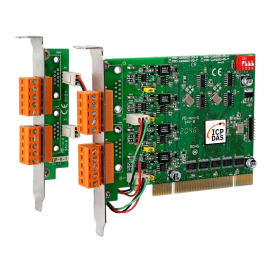
PISO-CAN200U-FD-D / PISO-CAN200U-FD-T
PISO-CAN400U-FD-D / PISO-CAN400U-FD-T
PISO-CANFD series CAN FD card User Manual (version 1.0.0)
Page: 1
Copyright © 2021 ICP DAS Co., Ltd. All Rights Reserved.
E-mail: service@icpdas.com
Advertisement
Table of Contents

Related Manuals for ICP DAS USA PISO-CAN-FD Series


Summary of Contents for ICP DAS USA PISO-CAN-FD Series
- Page 1 PISO-CANFD Series User Manual Version 1.0.0, Feb. 2021 Service and usage information for PISO-CAN200U-FD-D / PISO-CAN200U-FD-T PISO-CAN400U-FD-D / PISO-CAN400U-FD-T PISO-CANFD series CAN FD card User Manual (version 1.0.0) Page: 1 Copyright © 2021 ICP DAS Co., Ltd. All Rights Reserved. E-mail: service@icpdas.com...
- Page 2 Warranty All products manufactured by ICP DAS are under warranty regarding defective materials for a period of one year, beginning from the date of delivery to the original purchaser. Warning ICP DAS assumes no liability for any damage resulting from the use of this product.ICP DAS reserves the right to change this manual at any time without notice.
-
Page 3: Table Of Contents
Table of Contents Introduction ....................... 5 1.1. Specifications ....................6 1.2. Features ......................7 1.3. Overview ...................... 8 1.3.1. Board Layout ..................8 1.3.2. Pin Assignments .................. 10 1.3.3. Board Number Switch Settings ............11 1.3.4. Terminal Resistor Jumper Settings ..........12 Getting Started .................... - Page 4 3.1.8. CANFD_ActiveBoard ................. 44 3.1.9. CANFD_CloseBoard ................45 3.1.10. CANFD_BoardIsActive ..............46 3.5. CAN Bus API..................... 47 3.2.1. CANFD_Reset ..................47 3.2.2. CANFD_Init ..................48 3.2.3. CANFD_SetBitRate ................49 3.2.5. CANFD_SetBitRateWithSP .............. 51 3.2.6. CANFD_GetBitRate ................53 3.2.7. CANFD_GetBitRateWithSP ............. 55 3.2.8.
-
Page 5: Introduction
1. Introduction CAN FD (CAN with Flexible Data-Rate) is a newer extension version of the CAN 2.0 protocol. It was developed by Bosch and was released in 2012. It has been significantly improved during the standardization process and is nowadays in ISO 11898-1:2015. The CAN FD speeds up the data transmission and packs more data into each message. -
Page 6: Specifications
1.1. Specifications Model PISO-CAN200U-FD-D PISO-CAN400U-FD-D PISO-CAN200U-FD-T PISO-CAN400U-FD-T PC Bus Type Universal PCI, 3.3 V and 5 V, 33 MHz, 32-bit, plug and play Board No. By DIP switch CAN Interface Controller Microchip MCP2518FD Transceiver TI TCAN1042HG Ports Connector 9-pin Male D-Sub 5-pin screw terminal block CAN bit rates: 10 ~ 1000 kbps, Baud Rate... -
Page 7: Features
1.2. Features Compatible with the ISO 11898-2 standard Compatible with CAN specification 2.0 A/B and FD CAN FD support for ISO and Non-ISO (Bosch) standards switchable CAN FD bit rates for data field from 100 kbps to 10 Mbps ... -
Page 8: Overview
1.3. Overview The following is a description of the hardware settings for the PISO-CANFD series board, including the board layout, pin assignments, jumper and switch selection, LED indicators, and the configuration for the wiring connections. 1.3.1. Board Layout The following is the layout for the PISO-CANFD series board, illustrating the positions of the various connectors, jumpers and switches on the board. - Page 9 Figure 1.3-2 PISO-CAN400U-FD Board Layout Figure 1.3-3 ADP-9 Board Layout PISO-CANFD series CAN FD card User Manual (version 1.0.0) Page: 9 Copyright © 2021 ICP DAS Co., Ltd. All Rights Reserved. E-mail: service@icpdas.com...
-
Page 10: Pin Assignments
1.3.2. Pin Assignments The pin assignments for the 5-pin screw terminal connector and 9-pin Male D-Sub connector on the PISO-CANFD series board are shown below. Pin Assignments for the 5-pin screw terminal connector Pin No. Name Description CAN_GND CAN_Gnd, signal line for the CAN port. CAN_L CAN_Low, signal line for the CAN port. -
Page 11: Board Number Switch Settings
1.3.3. Board Number Switch Settings The following provides a description of the SW1 DIP switch, which can use to configure board number of the PISO-CANFD series board. Switch Description Status SW1 is a DIP switch that is used to configure the board number for the PISO-CANFD series card. -
Page 12: Terminal Resistor Jumper Settings
1.3.4. Terminal Resistor Jumper Settings The following provides a description of the resistor jumpers for the CAN Bus terminal resistor, which can be used to enable or disable the terminal resistor of PISO-CANFD series board. Jumper Description Status Used to enable or disable the 120Ω terminal resistor for CAN Bus Port1. -
Page 13: Getting Started
2. Getting Started This section is a description of how to begin using the PISO-CANFD series board, including installing the hardware, windows driver, making the wiring connections and using software utility and demos to test the board. 2.1. Installing the Hardware Step 1: Shut down and power off the computer. -
Page 14: Installing The Windows Driver
2.2. Installing Windows Driver To use the PISO-CANFD series board in a Windows environment, the correct driver for the specific version of the Windows operating system must be installed. The drivers can be downloaded from the ICP DAS website or the following link: https://www.icpdas.com/en/download/show.php?num=3200 The following is a description of the installation procedure for the Win10 operating system. - Page 15 Step 3: On the Update Driver Software – Network Controller screen, click the Browse my computer for driver software to continue. Step 4: Then Click the Browser…button to select the driver directory and click the Next button to start to install the driver. PISO-CANFD series CAN FD card User Manual (version 1.0.0) Page: 15 Copyright ©...
- Page 16 Step 5: Once the installation has been completed, click the Close button to exit. Step 6: After successfully to install the driver, you can see the PCM_PEX_PISO-CANFD Cards in CANFDCard item. PISO-CANFD series CAN FD card User Manual (version 1.0.0) Page: 16 Copyright ©...
-
Page 17: Wiring Connections
2.3. Wiring Connections In order to minimize any reflection effects on the CAN bus line, it must be terminated at each end using a terminator resistor, as illustrated in the diagram below. The specifications provided in ISO 11898-2 state that each terminator resistor must be 120 Ω... -
Page 18: Software Utility
2.4. Software Utility PISO-CANFD Utility is provided by ICP DAS to transmit / receive CAN/CAN FD messages for CAN Bus communication testing easily and quickly. In the meanwhile, it can also display the time-stamp of each received CAN/CAN FD messages for data analyzing conveniently. -
Page 19: Connect To The Board
2.4.1. Connect to the board When executing the Utility, the tool will try to scan all the necessary PISO-CANFD series board (including PISO-CAN200U-FD, PISO-CAN400U-FD) and list all scanned boards name on “Model Name” location of the Utility “Connect” frame. Before active the board, user can set the CAN port operation mode and CAN baudrate parameter of the board. - Page 20 “ISO CRC Enable” : ISO CRC operation mode. If this parameter is checked, this port will use the CAN FD frame format as specified by the ISO11898-1. Otherwise, CAN FD frame format will follow according to Bosch CAN FD Specification V1.0. [CAN Operation Mode] “CAN FD”...
- Page 21 “Acceptance Mask” : Specifies the “Acceptance Mask”that is used to determine which bit from the CAN ID will be checked by the CAN controller based on the value specified for the “Acceptance ID” parameter. If the bit of the “Acceptance Mask” parameter is set to 1, it means that the bit in the CAN ID in the same position needs to be checked, and the ID bit value needs to match the value specified for the bit of the “Acceptance ID”...
-
Page 22: Send Can/Can Fd Messages
2.4.2. Send CAN/CAN FD messages By using the Utiltiy tool, user can send CAN/CAN FD meesages to CAN Bus. After active the board, the screen for CAN Bus communication function will show up like below picture. The above is the illustration for the “Communication” screen and it can be divided to two blocks in each CAN port function. - Page 23 [Send Message] block: <1> “Send Message Configuration” frame : It is used to edit the CAN message parameters and users can use “Add” button to add the CAN message to “CAN/CAN FD Message Send Area”. Mode : CAN 11-bit (standard) ID or 29-bit (extended) ID. ...
- Page 24 <4> “Delete” button : It will delete the CAN message of the assigned blue row in “CAN/CAN FD Message Send Area”. <5> “Del Table” button : It will delete all the CAN messages in “CAN/CAN FD Message Send Area”. <6> “Send”...
-
Page 25: Receive Can/Can Fd Messages
2.4.3. Receive CAN/CAN FD messages By using the Utiltiy tool, user can review the received CAN meesages on the CAN Bus on the selected port. After active the board, the screen for CAN Bus communication function will show up like below picture. PISO-CANFD series CAN FD card User Manual (version 1.0.0) Page: 25 Copyright ©... - Page 26 [Receive Message] block: <1> “Start Record / Stop Record” button : When clicking “Start Record” button, the received CAN messages shown in “CAN Message Receive Area” will be recorded in a file as ASCII text. When clicking “Stop Record” button, it will stop recording the received CAN messages on a file.
- Page 27 <5> “Scroll / OverWrite Mode” option : “Scroll Mode”: The received CAN message data will be shown in “CAN Message Receive Area” by sequence. “Overwrite Mode”: If the MODE and ID value are all the same of the received CAN message data, then they will be placed in the same row of “CAN Message Receive Area”.
-
Page 28: Check Can Bus Status
2.4.4. Check CAN Bus Status By using the Utiltiy tool, user can review the CAN Bus status of the selected port. After active the board, user can open the “CAN Bus Status Monitor” frame on the “View” => “Bus Status Monitor” item. [Bus Status Monitor] block: <1>... - Page 29 RXWARN Receiver in Error Warning State bit Receiver not in Error Warning State (REC <= 95) Receiver in Error Warning State (128 > REC > 95) TXWARN: Transmitter in Error Warning State bit Transmitter not in Error Warning State (TEC <= 95) Transmitter in Error Warning State (128 >...
- Page 30 dominant level (data or identifier bit logical value ‘0’), but the monitored bus value was recessive. During the transmission of a message (with the exception of the NBIT1ERR:: arbitration field), the device wanted to send a recessive level (bit of logical value ‘1’), but the monitored bus value was dominant.
-
Page 31: Windows Api Function Reference
3. Windows API Function Reference This chapter describes the “pisocanfd” library APIs, including the System Information API, the CAN Bus API and an overview of the error codes, which can be helpful when developing custom applications. The library and demos can be downloaded from the ICP DAS web site. -
Page 32: Api Library Function Table
3.2. API Library Function Table All the functions provided in the pisocanfd API library are listed in the following table. System Information API Function Description Used to retrieve the version number for the function library file CANFD_GetDllVersion currently installed on the PISO-CANFD series board Used to retrieve PCI information related to a selected PISO-CANFD series board, including the vendor ID, device ID, CANFD_GetBoardInf... - Page 33 Used to retrieve the current bit rate configuration of the CAN port on CANFD_GetBitRate the selected PISO-CANFD series board Used to retrieve the current bit rate and baudrate sample point CANFD_GetBitRateWithSP configuration of the CAN port on the selected PISO-CANFD series board CAN filter configuration functions Used to set the CAN message filter of the CAN port on the selected...
- Page 34 port on the selected PISO-CANFD series board CAN bus status functions Used to retrieve the status of the CAN port on the selected CANFD_GetCANStatus PISO-CANFD series board Used to retrieve the bus diagnostic status of the CAN port on the CANFD_GetBUSDiagnostic selected PISO-CANFD series board PISO-CANFD series CAN FD card User Manual (version 1.0.0)
-
Page 35: Api Library Flow Diagram
3.3. API Library Flow Diagram The following is the basic control flow chart of user’s CAN Bus program development by using pisocanfd API library shown in following picture. PISO-CANFD series CAN FD card User Manual (version 1.0.0) Page: 35 Copyright © 2021 ICP DAS Co., Ltd. All Rights Reserved. E-mail: service@icpdas.com... -
Page 36: System Information Api
3.4. System Information API The following is an overview of the System Information API functions provided on the PISO-CANFD series board. A detailed description of each API is presented in subsequent sections. 3.1.1. CANFD_GetDllVersion Description This function is used to retrieve the version number of the pisocanfd.dll driver currently installed for the PISO-CANFD series board. -
Page 37: Canfd_Getboardinf
3.1.2. CANFD_GetBoardInf Description This function is used to retrieve PCI information of related to a specified PISO-CANFD series board, including the vendor ID, device ID, sub-vendor ID, sub-device ID, sub-auxiliary ID, logical interrupt number, board ID and board switch number. Syntax Int16 CANFD_GetBoardInf( Byte BoardNo,... - Page 38 wSDID [out] Indicates the address of a variable used to receive the sub-device ID. wSAuxID [out] Indicates the address of a variable used to receive the sub-auxiliary ID. wIrqNo [out] Indicates the address of a variable used to receive the logical interrupt number.
-
Page 39: Canfd_Totalboard
3.1.3. CANFD_TotalBoard Description This function is used to retrieve the total board number of PISO-CANFD series boards currently installed in the Host PC. Syntax Int16 CANFD_TotalBoard ( out Byte BoardNo Parameters BoardNo [out] Indicates the address of a variable used to receive the total number of PISO-CANFD series boards that were scanned. -
Page 40: Canfd_Getcardboardswitchno
3.1.4. CANFD_GetCardBoardSwitchNo Description This function is used to retrieve the current configuration of the DIP switch (SW1) on the specified PISO-CANFD series board. Syntax Int16 CANFD_GetCardBoardSwitchNo( Byte BoardNo, out Byte BoardSwitchNo Parameters BoardNo [in] Specifies the number of the PISO-CANFD series board to be read. The valid range is 0 to 15. -
Page 41: Canfd_Getcardboardid
3.1.5. CANFD_GetCardBoardID Description This function is used to retrieve the board id of the selected PISO-CANFD series board. Syntax Int16 CANFD_GetCardBoardID( Byte BoardNo, out Byte BoardID Parameters BoardNo [in] Specifies the number of the PISO-CANFD series board to be read. The valid range is 0 to 15. -
Page 42: Canfd_Getcardportnum
3.1.6. CANFD_GetCardPortNum Description This function is used to retrieve the number of the CAN port on a specified PISO-CANFD series board. Syntax Int16 CANFD_GetCardPortNum( Byte BoardNo, out Byte PortNum Parameters BoardNo [in] Specifies the number of the PISO-CANFD series board to be read. The valid range is 0 to 15. -
Page 43: Canfd_Getcardfpgafwver
3.1.7. CANFD_GetCardFPGAFWVer Description This function is used to retrieve the FPGA firmware version on a specified PISO-CANFD series board. Syntax Int16 CANFD_GetCardFPGAFWVer( Byte BoardNo, out Byte FPGAFWVer Parameters BoardNo [in] Specifies the number of the PISO-CANFD series board to be read. The valid range is 0 to 15. -
Page 44: Canfd_Activeboard
3.1.8. CANFD_ActiveBoard Description This function is used to activate a specified PISO-CANFD series board. Note that this function MUST be called before using any other API functions. Syntax Int16 CANFD_ActiveBoard( Byte BoardNo Parameters BoardNo [in] Specifies the number of the PISO-CANFD series board to be read. The valid range is 0 to 15. -
Page 45: Canfd_Closeboard
3.1.9. CANFD_CloseBoard Description This function is used to deactive a specified PISO-CANFD series board. This function MUST always be called at the end of a program in order for the system to release resources before exiting the program. Syntax Int16 CANFD_CloseBoard( Byte BoardNo Parameters BoardNo... -
Page 46: Canfd_Boardisactive
3.1.10. CANFD_BoardIsActive Description This function is used to check whether or not a specified PISO-CANFD series board is active. Syntax Int16 CANFD_BoardIsActive( Byte BoardNo, out Byte IsActive Parameters BoardNo [in] Specifies the number of the PISO-CANFD series board to be read. The valid range is 0 to 15. -
Page 47: Can Bus Api
3.5. CAN Bus API The following is an overview of the CAN Bus API functions provided on the PISO-CANFD series board. A detailed description of each function is presented in subsequent sections. 3.2.1. CANFD_Reset Description This function is used to reset the CAN chip for the CAN port on a specified PISO-CANFD series board. -
Page 48: Canfd_Init
3.2.2. CANFD_Init Description This function is used to initialize the CAN chip of the CAN port on a specified PISO-CANFD series board. After initializing, this CAN port will be in configuration mode. Syntax Int16 CANFD_Init ( Byte BoardNo, Byte Port Parameters BoardNo [in] Specifies the number of the PISO-CANFD series board to be read. -
Page 49: Canfd_Setbitrate
3.2.3. CANFD_SetBitRate Description This function is used to configure the CAN/CAN FD normal/data bit rate of the CAN port on a specified PISO-CANFD series board. After setting, this CAN port will be in configuration mode. Syntax Int16 CANFD_SetBitRate( Byte BoardNo, Byte Port, Uint32 NormalBitRate, Uint32 DataBitRate... - Page 50 of the PISO-CANFD series card. Unit: bps (bit per second). Valid Range: 100000 ~ 10000000 (100 kbps ~ 10000 kbps). Remark: The bit rate configured for CAN FD data phase (DataBitRate) must be higher or equal to the bit rate configured for the notmal arbitration phase (NormalBitRate).
-
Page 51: Canfd_Setbitratewithsp
3.2.5. CANFD_SetBitRateWithSP Description This function is used to configure the CAN/CAN FD normal/data bit rate and sample point of the CAN port on a specified PISO-CANFD series board. After setting, this CAN port will be in configuration mode. Syntax Int16 CANFD_SetBitRateWithSP( Byte BoardNo, Byte Port, Uint32 NormalBitRate,... - Page 52 DataBitRate [in] The bit rate configured for the CAN FD data phase in the assigned CAN port of the PISO-CANFD series card. Unit: bps (bit per second). Valid Range: 100000 ~ 10000000 (100 kbps ~ 10000 kbps). Remark: The bit rate configured for CAN FD data phase (DataBitRate) must be higher or equal to the bit rate configured for the notmal arbitration phase (NormalBitRate).
-
Page 53: Canfd_Getbitrate
3.2.6. CANFD_GetBitRate Description This function is used to retrieve the CAN/CAN FD baud rate configuration of the CAN port on a specified PISO-CANFD series board. Syntax Int16 CANFD_GetBitRate( Byte BoardNo, Byte Port, out Uint32 NormalBitRate, out Uint32 DataBitRate Parameters BoardNo [in] Specifies the number of the PISO-CANFD series board to be read. - Page 54 series card. Unit: bps (bit per second). Return Value If the function succeeds, the return value will be 0. If the function fails, refer to Section 3.6 Error Code Definitions. PISO-CANFD series CAN FD card User Manual (version 1.0.0) Page: 54 Copyright ©...
-
Page 55: Canfd_Getbitratewithsp
3.2.7. CANFD_GetBitRateWithSP Description This function is used to retrieve the CAN/CAN FD baud rate configuration and bit sample point of the CAN port on a specified PISO-CANFD series board. Syntax Int16 CANFD_GetBitRateWithSP( Byte BoardNo, Byte Port, out Uint32 NormalBitRate, out Uint32 DataBitRate, out Uint16 NormalSP, out Uint16 DataSP, Parameters... - Page 56 DataBitRate [out] Indicates the address of a variable used to retrieve the bit rate configured for the CAN FD data phase in the assigned CAN port of the PISO-CANFD series card. Unit: bps (bit per second). NormalSP [out] Indicates the address of a variable used to retrieve the normal arbitration phase bit sample point that is currently configured for the CAN Bus.
-
Page 57: Canfd_Setfilterallpass
3.2.8. CANFD_SetFilterAllPass Description This function is used to configure the CAN port on a specified PISO-CANFD series board to accept all (standard / extended, remote / data) frames. Syntax Int16 CANFD_SetFilterAllPass( Byte BoardNo, Byte Port Parameters BoardNo [in] Specifies the number of the PISO-CANFD series board to be read. The valid range is 0 to 15. -
Page 58: Canfd_Setfilterformat
3.2.9. CANFD_SetFilterFormat Description This function is used to configure the CAN port on a specified PISO-CANFD series board to accept standard or extended frames. Syntax Int16 CANFD_SetFilterFormat( Byte BoardNo, Byte Port, Byte inFormat Parameters BoardNo [in] Specifies the number of the PISO-CANFD series board to be read. The valid range is 0 to 15. -
Page 59: Canfd_Setfilter
3.2.10. CANFD_SetFilter Description This function is used to configure the CAN port on a specified PISO-CANFD series board to accept standard or extended frames depended on acceptance and mask parameter setting. Syntax Int16 CANFD_SetFilter ( Byte BoardNo, Byte Port, Byte inFormat, UInt32 inAcceptance, UInt32 inMask Parameters... - Page 60 [in] Specifies the “inAcceptance” that is used to determine which CAN IDs will be accepted by the CAN controller. inFormat inAcceptance (hexadecimal) Range standard frame (0) 000 to 7FF extended frame (1) 00000000 to 1FFFFFFF Note that inMask and inAcceptance arguments should verify: inAcceptance &...
-
Page 61: Canfd_Setopmode
3.2.11. CANFD_SetOPMode Description This function is used to configure the operation mode of the CAN port on a specified PISO-CANFD series board to CAN FD, CAN 2.0 and listen only mode. Syntax Int16 CANFD_SetOPMode( Byte BoardNo, Byte Port, Byte OPMode Parameters BoardNo [in] Specifies the number of the PISO-CANFD series board to be read. - Page 62 CAN 2.0 Supports Classic CAN 2.0 frames. This is a the Classic CAN 2.0 mode. This port will not receive CAN FD frames. It might send error frames if CAN FD frames are detected on the bus. Listen Only Listen Only mode is a variant of Normal CAN FD Operation mode.
-
Page 63: Canfd_Getopmode
3.2.12. CANFD_GetOPMode Description This function is used to get the operation mode of the CAN port on a specified PISO-CANFD series board Syntax Int16 CANFD_GetOPMode( Byte BoardNo, Byte Port, out Byte OPMode Parameters BoardNo [in] Specifies the number of the PISO-CANFD series board to be read. The valid range is 0 to 15. - Page 64 received. CAN 2.0 Supports Classic CAN 2.0 frames. This is a the Classic CAN 2.0 mode. This port will not receive CAN FD frames. It might send error frames if CAN FD frames are detected on the bus. Listen Only Listen Only mode is a variant of Normal CAN FD Operation mode.
-
Page 65: Canfd_Setisocrcen
3.2.13. CANFD_SetISOCRCEn Description This function is used to enable/disable the ISO/Non-ISO CRC in CAN FD Frames bit of the CAN port on a specified PISO-CANFD series board Syntax Int16 CANFD_SetISOCRCEn( Byte BoardNo, Byte Port, Byte ISOCRCEn Parameters BoardNo [in] Specifies the number of the PISO-CANFD series board to be read. The valid range is 0 to 15. - Page 66 Return Value If the function succeeds, the return value will be 0. If the function fails, refer to Section 3.6 Error Code Definitions. PISO-CANFD series CAN FD card User Manual (version 1.0.0) Page: 66 Copyright © 2021 ICP DAS Co., Ltd. All Rights Reserved. E-mail: service@icpdas.com...
-
Page 67: Canfd_Getisocrcen
3.2.14. CANFD_GetISOCRCEn Description This function is used to get the ISO/Non-ISO CRC setting of the CAN port on a specified PISO-CANFD series board Syntax Int16 CANFD_GetISOCRCEn( Byte BoardNo, Byte Port, out Byte ISOCRCEn Parameters BoardNo [in] Specifies the number of the PISO-CANFD series board to be read. The valid range is 0 to 15. - Page 68 Return Value If the function succeeds, the return value will be 0. If the function fails, refer to Section 3.6 Error Code Definitions. PISO-CANFD series CAN FD card User Manual (version 1.0.0) Page: 68 Copyright © 2021 ICP DAS Co., Ltd. All Rights Reserved. E-mail: service@icpdas.com...
-
Page 69: Canfd_Sendcanmsg
3.2.15. CANFD_SendCANMsg Description This function is used to transmit a CAN message from the CAN controller of a specified PISO-CANFD CAN port to the CAN network. Syntax Int16 CANFD_SendCANMsg ( Byte BoardNo, Byte Port, Byte Mode, Uint32 Id, Byte Type, Byte Dlc, Byte[] Data, Parameters... - Page 70 [in] CAN message ID parameter. standard CAN message (11-bit CAN ID) 0x000 ~ 0x7FF extended CAN message (29-bit CAN ID) 0x00000000 ~ 0x1FFFFFFF Type [in] The type of the message, where: 0: Indicates that the message is a remote-transmit-request message 1: Indicates that the message is a normal CAN data message 2: Indicates that the message is a CAN FD message with no bit rate switch 3: Indicates that the message is a CAN FD message with bit rate switch...
-
Page 71: Canfd_Recvcanmsg
3.2.16. CANFD_RecvCANMsg Description This function is used to retrieve a CAN message from the buffer of driver or CAN controller for a specified PISO-CANFD CAN port. Syntax Int16 CANFD_RecvCANMsg ( Byte BoardNo, Byte Port, out Byte Mode, out Uint32 Id, out Byte Type, out Byte Dlc, Byte[] Data,... - Page 72 0: Denotes the CAN standard ID, which uses a 11-bit CAN message ID. 1: Denotes the CAN extended ID, which uses a 29-bit CAN message ID. [out] CAN message ID parameter. standard CAN message (11-bit CAN ID) 0x000 ~ 0x7FF extended CAN message (29-bit CAN ID) ...
- Page 73 micro-seconds. L_MsgTimeStamps [out] Indicates the address of a variable used to retrieve the lower timestamp of the received CAN message in increments interval of 100 nano-seconds. The maximum value is 4,294,967,29.5 micro-seconds NOTE: The total timestamp of the received CAN message equals to “(UInt64) ((H_MsgTimeStamps <<...
-
Page 74: Canfd_Recvcanmsgcnt
3.2.17. CANFD_RecvCANMsgCnt Description This function is used to retrieve the count of the received CAN message for a specified PISO-CANFD CAN port. When user using IRQ method (call CANFD_InstallIrq) to receive CAN message, the value of “MsgCnt” will be the sum of message count in receive buffer of driver and hardware buffer of CAN controller. -
Page 75: Canfd_Setfifostatus
3.2.18. CANFD_SetFIFOStatus Description This function is used to clear the receive/ transmit data buffer of the CAN port on a specified PISO-CANFD series board. Syntax Int16 CANFD_SetFIFOStatus ( Byte BoardNo, Byte Port, Byte FIFOState Parameters BoardNo [in] Specifies the number of the PISO-CANFD series board to be read. The valid range is 0 to 15. - Page 76 reserved Return Value If the function succeeds, the return value will be 0. If the function fails, refer to Section 3.6 Error Code Definitions. PISO-CANFD series CAN FD card User Manual (version 1.0.0) Page: 76 Copyright © 2021 ICP DAS Co., Ltd. All Rights Reserved. E-mail: service@icpdas.com...
-
Page 77: Canfd_Getfifostatus
3.2.19. CANFD_GetFIFOStatus Description This function is used to get the receive/transmit data buffer overflow state of the CAN port on a specified PISO-CANFD series board. Syntax Int16 CANFD_GetFIFOStatus ( Byte BoardNo, Byte Port, out Byte FIFOState Parameters BoardNo [in] Specifies the number of the PISO-CANFD series board to be read. The valid range is 0 to 15. - Page 78 transmit buffer overfow reserved Return Value If the function succeeds, the return value will be 0. If the function fails, refer to Section 3.6 Error Code Definitions. PISO-CANFD series CAN FD card User Manual (version 1.0.0) Page: 78 Copyright © 2021 ICP DAS Co., Ltd. All Rights Reserved. E-mail: service@icpdas.com...
-
Page 79: Canfd_Getcanstatus
3.2.20. CANFD_GetCANStatus Description This function is used to retrieve the CAN bus error status and transmit/receive error counter of the CAN port on a specified PISO-CANFD series board. Syntax Int16 CANFD_CANGetStatus ( Byte BoardNo, Byte Port, out UInt16 CANStatus, out Byte TxErrorCount out Byte RxErrorCount Parameters BoardNo... - Page 80 Transmitter or Receiver is in Error Warning State RXWARN Receiver in Error Warning State bit Receiver not in Error Warning State (REC <= 95) Receiver in Error Warning State (128 > REC > 95) TXWARN Transmitter in Error Warning State bit Transmitter not in Error Warning State (TEC <= 95) Transmitter in Error Warning State (128 >...
-
Page 81: Canfd_Getbusdiagnostic
3.2.21. CANFD_GetBUSDiagnostic Description This function is used to retrieve the CAN bus error status (including separate error counters for receive/transmit and for nominal/data bit rates on BUSDiag0 and track of the kind of error that occurred since the last reading BUSDiag1) of the CAN port on a specified PISO-CANFD series board. - Page 82 23-16 DRERRCNT Data Bit Rate Receive Error Counter bits 31-24 DTERRCNT Data Bit Rate Transmit Error Counter bits BUSDiag1 [out] BUSDIAG1 keeps track of the kind of error that occurred since the last clearing of the register. The register also contains the error-free message counter.
-
Page 83: Error Code Definitions
3.6. Error Code Definitions This following are the definitions for the error codes that may be encountered while operating the PISO-CANFD. Error Code Error ID Error Description (hexadecimal) 0x000 ERR_NO_ERR No error An error occurred while 0x001 ERR_INIT_DRIVER_ERROR initializing the driver An error occurred while 0x002 ERR_COMM_DRIVER_ERROR... - Page 84 CAN mask filter setting large than 0x7FF The extended identifier of 0x025 ERR_FLT_EXT_ACM_TOOLARGE_ERROR CAN mask filter setting large than 0x1FFFFFFF. CAN operation mode setting 0x030 ERR_INVALID_OPMODE_ERROR is not support 0x031 ERR_SOFTBUFF_IS_EMPTY CAN receive buffer is empty CAN normal bit rate setting is 0x032 ERR_NORM_BITRATE_NOT_SUPP_ERROR not support...
- Page 85 transmiting a CAN message CAN receive buffer of driver is 0x121 ERR_SYS_SOFTBUFF_IS_EMPTY empty CAN receive buffer of driver is 0x122 ERR_SYS_SOFTBUFF_IS_FULL full CAN receive buffer of CAN 0x123 ERR_SYS_HARDWAREBUFF_IS_EMPTY chip is empty CAN transmit buffer of CAN 0x124 ERR_SYS_HARDWAREBUFF_IS_FULL chip is full PISO-CANFD series CAN FD card User Manual (version 1.0.0) Page: 85 Copyright ©...
-
Page 86: Appendix
4. Appendix 4.1. Revision History This chapter provides revision history information to this document. The table below shows the revision history. Revision Date Description 1.0.0 2021/01/31 Initial issue PISO-CANFD series CAN FD card User Manual (version 1.0.0) Page: 86 Copyright © 2021 ICP DAS Co., Ltd. All Rights Reserved. E-mail: service@icpdas.com... -
Page 87: Dimensions
4.2. Dimensions 4.2.1. PISO-CAN200U-FD-D / PISO-CAN400U-FD-D PISO-CANFD series CAN FD card User Manual (version 1.0.0) Page: 87 Copyright © 2021 ICP DAS Co., Ltd. All Rights Reserved. E-mail: service@icpdas.com... -
Page 88: Piso-Can200U-Fd-T / Piso-Can400U-Fd-T
4.2.2. PISO-CAN200U-FD-T / PISO-CAN400U-FD-T PISO-CANFD series CAN FD card User Manual (version 1.0.0) Page: 88 Copyright © 2021 ICP DAS Co., Ltd. All Rights Reserved. E-mail: service@icpdas.com...
Need help?
Do you have a question about the PISO-CAN-FD Series and is the answer not in the manual?
Questions and answers