Table of Contents
Advertisement
Quick Links
Check the Supplied Items
The package includes the following items:
Installing the Windows Driver
Step 1: Setup the Windows driver. The driver is located at:
The UniDAQ driver supports 32-/64-bit Windows 2K/XP/2003/Vista/7/8; it is
recommended to install this driver for new user:
CD: \NAPDOS\PCI\UniDAQ\DLL\Driver
http://ftp.icpdas.com/pub/cd/iocard/pci/napdos/pci/unidaq/dll/driver/
The PISO-DIO Series classic driver supports Windows 98/NT/2K and 32-bit XP/2003/
Vista/7/8. Recommended to install this driver for have been used PISO-DIO series
boards of regular user, please refer to :
http://ftp.icpdas.com/pub/cd/iocard/pci/napdos/pci/piso-dio/manual/quickstart/
classic/
1
PEX-P32A32/PISO-P32A32U Series Quick Start Guide
WebSite: http:// www.icpdas.com.tw
For PEX-P32A32
PISO-P32A32U(-5V) Series
English/Jun. 2015/Version 1.1
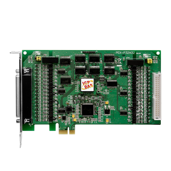
One PEX-P32A32 or PISO-P32A32U (-5V) PCI Board.
One Software Utility CD (V6.2 or later)
One Quick Start Guide (This Document)
One CA-4037B Cable
E-Mail: service@icpdas.com , service.icpdas@gmail.com
Two CA-4002 D-Sub connectors
ICP DAS CO., LTD.
Advertisement
Table of Contents

Summary of Contents for ICP DAS USA PISO-P32A32U-5V Series
- Page 1 For PEX-P32A32 PISO-P32A32U(-5V) Series English/Jun. 2015/Version 1.1 Check the Supplied Items The package includes the following items: One PEX-P32A32 or PISO-P32A32U (-5V) PCI Board. One Software Utility CD (V6.2 or later) One Quick Start Guide (This Document) One CA-4037B Cable Two CA-4002 D-Sub connectors Installing the Windows Driver Step 1: Setup the Windows driver.
-
Page 2: Jumper Setting
Step 2: Click the “Next>” button to start the installation. Step 3: Check your DAQ Card is or not on supported list, then click the “Next>” button. Step 4: Select the installed folder, the default path is C:\ICPDAS\UniDAQ, confirm and click the “Next>”... -
Page 3: Installing The Hardware
Installing the Hardware Step 1: Shut down and power off the computer. Step 2: Remove all the covers from the computer. Step 3: Select an unused PCI Express/PCI slot. Step 4: Carefully insert your card into the PCI Express/PCI slot and secure the board in place. Step 5: Replace the covers on the computer. -
Page 4: Pin Assignments
Pin Assignments Extension Cable (CA-4037B): DB-40-Pin conversion DB-37-Pin PEX-P32A32/PISO-P32A32U Series Quick Start Guide ICP DAS CO., LTD. WebSite: http:// www.icpdas.com.tw E-Mail: service@icpdas.com , service.icpdas@gmail.com... - Page 5 Self-Test Prepare for device: DN-37 (optional) wiring terminal board. Exterior power supply device. For example: DP-665 (optional) Self-test wiring as follows: Step 1: Connect the DN-37 to the CON1 connector on your board using the CA-3710 cable. Step 2: Keep set the JP1 and JP2 jumper to External Power (See Section 3 Jumper Setting).
- Page 6 The PEX-P32A32/PISO-P32A32U wiring is illustrated in the figure below: +24V External: DP-665 CON1 Cable: CA-3710 DN-37 I/O Wiring 20 21 22 23 24 25 26 27 28 29 30 31 32 33 34 35 36 10 11 13 14 15 16 The PISO-P32A32U-5V wiring is illustrated in the figure below: +24V External: DP-665...
- Page 7 Step 5: Execute the UniDAQ Utility Program. 1. In Windows 7, click the “Start” button, point to “All Programs”, and then click the “ICPDAS” folder. Point “UniDAQ Development Kits”and then click “UniDAQ Utility” to execute the UniDAQ Utility Program. 2. Confirm that PEX/PISO-P32A32 Series board has been successfully installed in the Host system.
- Page 8 4. Click the “Digital Input” tab. 5. Select “Port0” from the “Port Number” drop-down menu. 6. The DI indicators will turn black when the corresponding DO channels 0, 2, 4 and 6 are ON. Note: All the DI should become red because all the DO is OFF (uncheck).


Need help?
Do you have a question about the PISO-P32A32U-5V Series and is the answer not in the manual?
Questions and answers