
Related Manuals for Thermo Scientific 3403


Summary of Contents for Thermo Scientific 3403
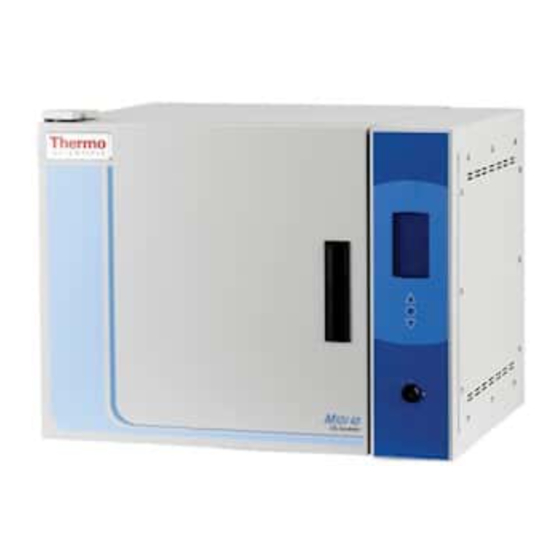
- Page 1 Midi 40 CO2 Incubator Models 3403 and 3404 Service Manual 7993403 Rev. 2 _________________________________________________________________________________ Part of Thermo Scientific...
- Page 2 Preface Manual Number 7993403 28728 6/18/12 Added full CO2 calibration procedure - Section 7 27807 10/3/11 Updated with op manual revisions 12/10/09 Original, was 97665H08 ECR/ECN DATE DESCRIPTION Thermo Scientific Midi 40 CO2 Incubator...
- Page 3 It is not intended to teach unqualified persons on applicable equipment all procedures necessary to make repairs. ©2009 Thermo Fisher Scientific. All rights reserved. Midi 40 CO2 Incubator Thermo Scientific...
- Page 4 Always use the proper protective equipment (clothing, gloves, goggles, etc.) 4 Always dissipate extreme cold or heat and wear protective clothing. 4 Always follow good hygiene practices. 4 Each individual is responsible for his or her own safety. Thermo Scientific Midi 40 CO2 Incubator...
- Page 5 We can also provide you with a quotation on our Extended Warranty for your Thermo Scientific products. Whatever Thermo Scientific products you need or use, we will be happy to discuss your applications. If you are experiencing technical problems, working together, we will help you locate the problem and, chances are, correct it yourself...over the telephone without a service...
-
Page 6: Table Of Contents
Troubleshooting Guide ........5-4 Thermo Scientific Midi 40 CO2 Incubator... - Page 7 Parts List ..........9-2 Midi 40 CO2 Incubator Thermo Scientific...
-
Page 8: General Information
Each chamber consists of two sections: the cabinet (where the product is stored) and the control section (containing the temperature, CO2, and humidity control systems). On single-chamber models, the control section is to the side of the cabinet. Thermo Scientific Midi 40 CO2 Incubator... -
Page 9: Included Parts
1/4 in. (476 mm) ID clear tubing for the gas connection • Cordset • 5” round humidity pan • Additional CO sensor gasket • disposable filter 99.97 Filter Additional gasket Operating manual Humidity Cordset Tubing Figure 4-1. Included Components (shelves and brackets not shown) Midi 40 CO2 Incubator Thermo Scientific... -
Page 10: Wiring Cautions
The data plate is mounted on the outside of the cabinet, beside the upper door hinge. Some older models may have the plate mounted on the front of the frame, just above the lower door hinge. Thermo Scientific Midi 40 CO2 Incubator... -
Page 11: Component Locations
Section 1 General Information Component Locations dataplate on left side Inside Chamber sensor humidity pan Upper back of unit Lower back AS-485 Ports of unit Sample Port Power inlet CO2 inlet Midi 40 CO2 Incubator Thermo Scientific... -
Page 12: Safety
Interlocks, relays, and switches are designed with a specific purpose and should, therefore, not be altered. • Caution The user is responsible for carrying out appropriate decontamination procedures when hazardous materials are spilled on or inside the incubator. Thermo Scientific Midi 40 CO2 Incubator... - Page 13 Electrical wiring and all grounds must be correctly reconnected and secured away from sharp edges, components and moving parts. All panels and covers should be reinstalled before the incubator is plugged in. Midi 40 CO2 Incubator Thermo Scientific...
- Page 14 Note Be sure to reference any applicable wiring diagram(s) when • reconnecting and replacing electrical components. • Note Throughout this service manual, additional safety precautions dealing with specific procedures may be presented. This information should be carefully read and observed. Thermo Scientific Midi 40 CO2 Incubator...
-
Page 15: Technical Information
• All-steel cabinet with high-impact epoxy finish for easy cleaning • Adjustable stainless steel interior shelves • All the unit exteriors are constructed of painted, cold roll steel. • One glass inner door with positive latch Thermo Scientific Midi 40 CO2 Incubator... -
Page 16: Alarm Monitoring System
• Touchpad alarm test • Power failure or temperature deviation outside alarm set limits triggers audible and visual warning. • Independent high and low alarm setpoints adjustable in 0.1 increments • RS485 connections for remote monitoring Midi 40 CO2 Incubator Thermo Scientific... -
Page 17: Control Systems Theory
Door Heat System Heating the inner surface of the outer door with a low wattage, large area heater provides enough radiant heat to the glass door to control condensation. The microprocessor controls the door heater. Thermo Scientific Midi 40 CO2 Incubator... -
Page 18: Preventive Maintenance And Diagnostics
±0.1°C. • Electrical wires - Check the electrical control box for any burnt or discol- ored wires due to lose connections or low voltage conditions. 1. Maintenance should only be performed by trained personnel. Thermo Scientific Midi 40 CO2 Incubator... -
Page 19: Recommended Tool List
• Electronic Digital Thermometer (reads ±0.1°C) • Digital Voltmeter, 4-1/2 digit • Cordless Screwdriver (reversible) • Ammeter (4mA – 5A, digital) • CO2 Gas Analyzer • Phillips Screwdrivers Midi 40 CO2 Incubator Thermo Scientific... -
Page 20: Troubleshooting Parameter List
Press ‘mode’ button = “Set CO2 HIGH Alarm” _________ Press ‘mode’ button = “Set CO2 LOW Alarm” _________ Press ‘mode’ button = “Set Temp OFFSET” _________ (Actual) and ________ (Offset) Press ‘mode’ button = “Set CO2 OFFSET” _________ (Actual) and _________ (Offset) Thermo Scientific Midi 40 CO2 Incubator... -
Page 21: Troubleshooting Guide
• Always wipe surfaces with mild detergent and water to remove bleach residue. • Never use a steel-wool soap pad on interior surfaces. Use a non- metallic pad (e.g., Scotch-Brite). • Corrosive culture media can cause oxidation. Midi 40 CO2 Incubator Thermo Scientific... -
Page 22: Maintenance & Repair Procedures
Connect the other side of the filter to the incubator’s barbed fitting. 5. Turn on gas supply and resume normal operation. From Incubator Supply Figure 6-1. Gas Filter Thermo Scientific Midi 40 CO2 Incubator... -
Page 23: Replacing The Temperature Sensor
7. Use 100% silicone to seal the opening where the sensor enters the chamber. 8. Calibrate the temperature control in accordance with the Temperature Calibration procedure in this section. Figure 6-4. Temp Sensor Connector Midi 40 CO2 Incubator Thermo Scientific... -
Page 24: Replacing Co2 Sensor And Interface Pcb
8. Install the new PCB in the reverse order. 9. Install both covers and all mounting screws. 10. Plug in unit and turn on the main power switch. 11. Allow temperature to stabilize and calibrate the CO2 control Thermo Scientific Midi 40 CO2 Incubator... -
Page 25: Replacing Printed Circuit Boards
Use caution that neither the cable nor the connector is damaged when removing the bezel. Note If replacing the Main Control board, perform Steps 1-3 of the TC CO2 Calibration Procedure in this section before turning power switch to “Off ”. Midi 40 CO2 Incubator Thermo Scientific... -
Page 26: Testing The Outer Door Heater
“open” or infinite resistance. 6. If the resistance is good, replace the wires and cover/tray. Turn power switch to “On” and resume normal operation. If the resistance is incorrect, replace the door. Thermo Scientific Midi 40 CO2 Incubator... -
Page 27: Replacing The Outer Door Heater
8. Cut the wires of the new heater as short as possible, but still long enough to connect with wire nuts. 9. Connect the new heater with wire nuts and install the new inner liner and door in the reverse order. Midi 40 CO2 Incubator Thermo Scientific... -
Page 28: Replacing Co2 Solenoid Assembly
6. Remove the 2 mounting bracket screws and remove the solenoid from the control housing. 7. Remove the bracket from the solenoid. 8. Install the replacement solenoid in the reverse order. Thermo Scientific Midi 40 CO2 Incubator... -
Page 29: Calibration
Note If user does not push any keys after approximately thirty seconds, the display will revert back to the normal Run mode . If a value was changed, whatever value was last displayed will be stored as the new setting. Thermo Scientific Midi 40 CO2 Incubator... -
Page 30: Temperature Calibration
8. Enter Program Mode, go to “Set Temp OFFSET” option and press the up/down arrow to match the display to a calibrated instrument. 9. For any offset adjustments made, allow at least 1 hour between adjustments to permit the unit to stabilize again. Midi 40 CO2 Incubator Thermo Scientific... -
Page 31: Co2 Calibration
FYRITE, lower the CO2 control set point in Program mode 1.0% below your current set point, e.g. from 5% to 4%. This step is necessary to prevent CO2 gas injection during the calibration of the unit. Thermo Scientific Midi 40 CO2 Incubator... - Page 32 The delay in the update is due to how the system microprocessor averages CO2 measurements, the displayed value will not update immediately! Midi 40 CO2 Incubator Thermo Scientific...
-
Page 33: Appendices
(code must be compiled with SN Init And Test) Mode + Dec Inc + Dec Restore Defaults / Manual Reset Mode + Inc + Dec Board Test Mode (if compiled with UL Testing, then UL Test Mode) Thermo Scientific Midi 40 CO2 Incubator... -
Page 34: Intrlogic Test Points And Jumpers
CPU TP2 5 VDC (regulated from line or battery) CPU TP6 4.5 VDC Reference CPU TP15 -1.6 VDC Offset (H05 version only) CPU TP4 Battery Voltage 15.3VDC typical CPU TP5 -5 VDC (H05 version only) Midi 40 CO2 Incubator Thermo Scientific... -
Page 35: How To Enter Test Mode
This test simply writes a byte of data (0xA5) to a non-volatile memory address (0xF0) within the 9356 IC. Next, the location is read to a local RAM to ensure proper operation of the 9356. On success, the display shows “0 P”; on fail, “0 F.” Thermo Scientific Midi 40 CO2 Incubator... - Page 36 It does NOT effect the normal battery test frequency. Test 13/D (Audible Test) This test activates the beeper for 3 seconds to ensure proper operation. Midi 40 CO2 Incubator Thermo Scientific...
-
Page 37: Telemetry Tables
Commands are a simple ASCII character and some repeat with a set frequency and some merely output data one time. Date may be text, integer, floating point, or hexadecimal values. Thermo Scientific Midi 40 CO2 Incubator... - Page 38 Param 3: Incubator only - CO2 concentration (divide by 10 to convert to %) Param 4: O2 Control only…O2 concentration (divide by 10 to convert to %) Param 5: Relative humidity (divide by 10 to convert to %) Midi 40 CO2 Incubator Thermo Scientific...
- Page 39 'F' COMMAND Repeat: YES Frequency: Every two seconds Compile Dependencies: NONE Description: This command dumps the variable FlagBank which is spe- cific to each version of code. Requires understanding of memory map to be useful. Thermo Scientific Midi 40 CO2 Incubator...
- Page 40 Param 6: O2 Control only - O2 rapid recovery time (used only in rapid recovery mode) Param 7: RH Control only - Relative humidity heater PWM Param 8: RH Control only - Relative humidity water source PWM Midi 40 CO2 Incubator Thermo Scientific...
- Page 41 Param 5: Water RTD (divide by 10 to convert to °C) Param 6: Door integral Param 7: Water integral Param 8: High temperature excursion (divide by 10 to convert to °C) Param 9: Low temperature excursion (divide by 10 to convert to °C) Thermo Scientific Midi 40 CO2 Incubator...
-
Page 42: Detailed Descriptions Of Intrlogic Pcbs
Param 2: Port B (local RAM image of 8255 port) Param 3: Port C (local RAM image of 8255 port) Param 4: Relay Register (local RAM image of 5891 data) Detailed Descriptions of IntrLogic PCBs Figure 7-1. Power Printed Circuit Board (PCB) 8-10 Midi 40 CO2 Incubator Thermo Scientific... -
Page 43: Relay And Triac Allocation On Power Pcb
If the results do not match those described and the system is working correctly otherwise, replace the power board. K2 No Connection This output is not used in the current design. K6 No Connection This output is not used in the current design. Thermo Scientific Midi 40 CO2 Incubator 8-11... - Page 44 Test Points (as labeled on the silkscreen) TP1 “LM335-1” TP6 “+4.5V” TP11 “RTD2” TP2 “+5V” TP7 “LM335-2” TP12 “RTD3” TP3 “GND” TP8 “+12V” TP13 “TC” TP4 “VBAT” TP9 “LM335-3” TP14 “AC Mon” TP5 “-5V” TP10 “RTD1” TP15 “-1.6 Adj” 8-12 Midi 40 CO2 Incubator Thermo Scientific...
-
Page 45: General Overview
0 is found to be 5.4 VDC, the readings on channels 1-7 may be corrupt. Because TC sensor readings are adjusted or compensated due to the presence of RH, an erroneous RH reading can cause incorrect CO2 results. Thermo Scientific Midi 40 CO2 Incubator 8-13... - Page 46 - 21.75) / (1 + (T - 23)*2.4E-03) in mV, RH in %, T in °C] = Sensor RH/(1.0546 – 0.00216T), T in °C TEMP. COMP. is ultimately the value to be displayed. If the values correlate TEMP. COMP. 8-14 Midi 40 CO2 Incubator Thermo Scientific...
- Page 47 The RTD element in the H2O / Tank RTD probe is not at the very end of the heat shrink. • A poorly insulated steam generator. • Heat source near the left rear of the incubator. Thermo Scientific Midi 40 CO2 Incubator 8-15...
- Page 48 Conditioning of the cabinet probe can usually be traced to an improper- ly isolated steam generator or another source of heat on top of the incubator. 8-16 Midi 40 CO2 Incubator Thermo Scientific...
- Page 49 With this value it is straightforward to check a measurement at TP14 against the displayed percentage. In addition, the sensor is a stand-alone device - the voltage can be checked at the sensor’s molex connector with it completely out of circuit. Thermo Scientific Midi 40 CO2 Incubator 8-17...
- Page 50 (F) for the corresponding tank. Note that pin 1 is closest to the component designator label (J21 or J22). J22 pin 1 to 2 J22 pin 3 to 4 J21 pin 1 to 2 J21 pin 3 to 4 8-18 Midi 40 CO2 Incubator Thermo Scientific...
- Page 51 DATA OUT x (Max Count) – GND) (n-bit) Result is basically a ratio of VIN to VREF, normalized to VREF in binary format. Simplified example: VOLTAGE A/D Output FFFFFF (Max. Count) Temperature Temperature Thermo Scientific Midi 40 CO2 Incubator 8-19...
-
Page 52: Interface Pcb
= 4.5 V Resolution = 0.0000002682209174765 Volts ≅ 0.000000268 Volts 2.68 x 10 (¼ μV) Interface PCB I/O SUMMARY J1 – N/A Used only for ULT application Figure 7-5. Interface PCB (P/N 192039) 8-20 Midi 40 CO2 Incubator Thermo Scientific... - Page 53 Pin 3 – “SW-DOWN” Input from DOWN keypad. Grounding this pin will simulate the ‘down’ pad being pressed. Pin 4 - Ground – common to one side of each of the keypads. Thermo Scientific Midi 40 CO2 Incubator 8-21...
- Page 54 Section 8 Appendices J4 – Input from Key Switch For reference, wiring diagram 3403-70-1 provides a schematic depiction of the key switch and J4. Pin 1 is toward the top of the board, away from “J4” label. Pin 1 – “+5V” Output to key switch Pin 2 –...
- Page 55 Pins 2, 4, 6, 8, 10, 12, 14, 16, 18, 20, 22, 24 - Ground Pin 15 – Serial Data Pin 19 – Blank Pin 21 – Serial Clock Pin 23 – Latch Pin 26 - +5V J7 - Ground and 5 VDC Out to VFD Display Thermo Scientific Midi 40 CO2 Incubator 8-23...
-
Page 56: Co2 Sensor Pcb
This is the voltage produced by the R1/R4 voltage divider. Under proper operation, this will measure in the ~2.4VDC range. If the sensor is open circuit, this point will measure ~5.4VDC. Pin 1 is closest to the “JP2” label. 8-24 Midi 40 CO2 Incubator Thermo Scientific... - Page 57 Section 8 Appendices Figure 7-6. Control Housing, Main Components 1. CPU PCB 2. Power PCB 3. CO2 Solenoid 4. 12V Gel Celll battery Thermo Scientific Midi 40 CO2 Incubator 8-25...
- Page 58 1232.39 1089.58 1163.11 1236.23 1093.46 1166.97 1240.07 1097.34 1170.83 1243.90 1101.22 1174.69 1247.74 1105.09 1178.54 1251.57 1108.97 1182.39 1255.40 1112.84 1186.25 1259.23 1116.72 1190.10 1263.06 1120.59 1193.95 1266.89 1124.46 1197.80 1270.72 1128.33 1201.65 Thermo Scientific Midi 40 CO2 Incubator 8-26...
- Page 59 Thermo Scientific Midi 40 CO2 Incubator...
-
Page 60: Electrical Schematic And Parts List
Door Gasket, Inner Assy 103140 Door, Glass Assy 1900435 Latch, Glass Door Assy 1900436 Outer Door Gasket 990044 Door Switch Harness 350062 Power Cord 125V USA 430108 Pwer Cord 250V European 430109 E-PROM Assy 320546 Midi 40 CO2 Incubator Thermo Scientific... - Page 61 Thermo Fisher Scientific 401 Millcreek Road Marietta, Ohio 45750 United States www.thermofisher.com...
Need help?
Do you have a question about the 3403 and is the answer not in the manual?
Questions and answers