
Related Manuals for Thermo Scientific 3950


Summary of Contents for Thermo Scientific 3950
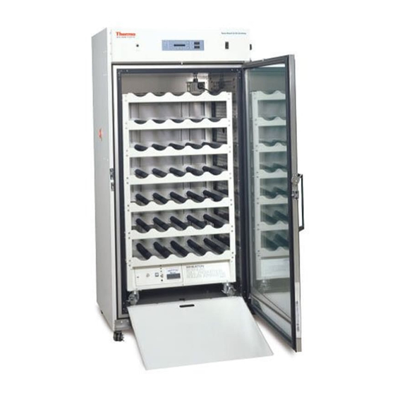
- Page 1 Model 3950 and 3951 Forma 29 cu. ft. Reach-In Incubator Operating and Maintenance Manual 7003950 Rev. 21 Visit us online to register your warranty www.thermoscientific.com/labwarranty...
- Page 2 200-230 * T/C is a thermal conductivity sensor. ** All units are 50/60 Hz. Manual Number 7003950 29318//IN-4272 12/14/12 Clarified usage on exploded drawing 3950-08-4 list 28773/IN-4231 10/8/12 Updated Figure 1-6 to current 28267 2/20/12 Added cautions for running high RH or temps...
- Page 3 Thermo Fisher Scientific makes no representations or warranties with respect to this manual. In no event shall Thermo be held liable for any damages, direct or incidental, arising out of or related to the use of this manual. ©2000 Thermo Fisher Scientific. All rights reserved. Reach-In Incubator Thermo Scientific...
- Page 4 European Country, and this product should be disposed of or recycled through them. Further information on Thermo’s compliance with this directive, the recyclers in your country and information on Thermo Scientific products will be available at www.thermofisher .com. Always use the proper protective equipment (clothing, gloves, goggles, etc.) 4 Always dissipate extreme cold or heat and wear protective clothing.
- Page 5 We can also provide you with a quotation on our Extended Warranty for your Thermo Scientific products. Whatever Thermo Scientific products you need or use, we will be happy to discuss your applications. If you are experiencing technical problems, working together, we will help you locate the problem and, chances are, correct it yourself...over the telephone without a service...
-
Page 6: Section 2 Calibration
• Repairs to parts or systems resulting from unauthorized unit modifications. • Any labor costs other than that specified during the parts and labor warranty period, which may include additional warranty on CO sensors, blower motors, water jackets, etc. Thermo Scientific Reach-In Incubator... -
Page 8: Table Of Contents
Set RS485 Address ........3-7 Thermo Scientific... - Page 9 Warranty ...........10-1 Reach-In Incubator Thermo Scientific...
-
Page 10: Installation And Start-Up
Installation and Start-Up Section 1 Figure 1-1. Front View Figure 1-2. Side View Figure 1-4. Top View Figure 1-3. Back View Thermo Scientific Reach-In Incubator... -
Page 11: Control Panel Keys, Displays, & Indicators
Scroll for Parameters Arrows - Moves the operator through the choices of the selected mode. Inject Indicator - Lights when CO is being injected into the incu- bator. % CO2 Display - Displays CO percentage continuously. Reach-In Incubator Thermo Scientific... -
Page 12: Keypad Operation
Section 1 Installation and Start-Up Keypad Operation The Model 3950 Series Reach-In Incubator has four basic modes that allow incubator setup: Run, Setpoints, Calibration and System Configuration. • Run is the default mode during normal operation. • Set is used to enter system setpoints. -
Page 13: Unit Installation
Accidental spills of hazardous materials on or inside this unit are the responsibility of the user. Reach-In Incubator Thermo Scientific... -
Page 14: Installing The Shelves
(30 PSIG max.) to 3/8” ID hose Back of Unit Chamber Drain (Overflow) - 3/8” elbow with 3/8” hose barb fitting. Install with fitting sloping slightly downward. Back View Floor Figure 1-6. Top View of Fitting Connections Thermo Scientific Reach-In Incubator... -
Page 15: The Water Supply
When the reservoir is full, a 10-second audible tone is heard and the ADD WATER message no longer displays. Reach-In Incubator Thermo Scientific... -
Page 16: Connecting The Unit To Electrical Power
Position the incubator so the unit can be easily disconnected. Plug the provided power cord into the power inlet connector on the back of the cabinet, then into a grounded, dedicated electrical circuit. Thermo Scientific Reach-In Incubator... -
Page 17: Connecting The Co Gas Supply
Section 1 Installation and Start-Up Connecting to Electrical The Model 3950 Series also has an internal outlet located on the right side of the interior back wall. The outlet is to provide power (230W maximum) Power (continued) to accessory equipment. This outlet is not to be used when the temperature is above 40°C and the RH more than 50%. -
Page 18: Incubator Start-Up
5. Press the Mode key until the Run indicator lights for Run mode or press the right/left arrow keys to go to next/previous parameter. Caution Any equipment placed inside chamber must be rated for unit operating temperature and humidity. Thermo Scientific Reach-In Incubator... -
Page 19: Setting The Overtemp Setpoint
All Model 3950 Series incubators are equipped with a secondary temperature monitoring system to monitor the air temperature inside the cabinet. This system is designed as a safety device to turn off all heaters in the event of a temperature control failure. - Page 20 4. Press Enter to save the setpoint. 5. Press the Mode key until the Run indicator lights to go to Run mode, or press the right/left arrow keys to go to next/previous parameter. Thermo Scientific Reach-In Incubator 1-11...
- Page 21 Section 1 Installation and Start-Up 1-12 Reach-In Incubator Thermo Scientific...
-
Page 22: Calibration
Temperature Stabilization Periods Start-Up - Allow 12 hours for the temperature in the cabinet to stabilize before proceeding. Presently Operating - Allow at least 2 hours after the display reaches setpoint for temperature to stabilize before proceeding. Thermo Scientific Reach-In Incubator... -
Page 23: Calibrating The Co System
5. Press the Mode key to return to Run or the right/left arrow to go to next/previous parameter. Calibrating the CO Model 3950 Series incubators have a CO sensor. The incubator atmosphere is not only effected by the quantity of CO... - Page 24 5. Press the up /down arrows to change the display to match the independent instrument. 6. Press Enter to store the calibration. 7. Press the Mode key to return to Run or the right or left arrows to go to the next/ previous parameter. Thermo Scientific Reach-In Incubator...
- Page 25 Section 2 Calibration Reach-In Incubator Thermo Scientific...
-
Page 26: Configuration
2. Press right arrow until Audible XXX is displayed in message center. 3. Press up/down arrow to toggle Audible ON/OFF. 4. Press Enter to save the setting. 5. Press Mode key to return to Run mode or right/left to go to next/previous parameter. Thermo Scientific Reach-In Incubator... -
Page 27: Set An Access Code
3. Press up/down arrow to change the low temp alarm limit. 4. Press Enter to save the low temp alarm limit. 5. Press the Mode key to return to Run mode or right/left to go to next/previous parameter. Reach-In Incubator Thermo Scientific... -
Page 28: Enable Temp Alarms To Trip Relay Contacts
3. Press up/down arrow to change the low CO alarm limit. 4. Press Enter to save the low CO alarm limit. 5. Press the Mode key to return to Run mode or right/left to go to next/previous parameter. Thermo Scientific Reach-In Incubator... -
Page 29: Set High Co Alarm Limit
2. Press the right arrow until CO2 RLY XXX is displayed in the message center. 3. Press up/down arrow to toggle the setting ON/OFF. 4. Press Enter to save the setting. 5. Press the Mode key to return to Run Mode or right/left to go to next/previous parameter. Reach-In Incubator Thermo Scientific... -
Page 30: Set New Zero No. For New Co Sensors
3. Press up/down arrow to change the span number to match the sticker. 4. Press Enter to save the setting. 5. Press the Mode key to return to Run mode or right/left to go to next/previous parameter. Thermo Scientific Reach-In Incubator... -
Page 31: Enable The High Humidity Feature
3. Press the up/down arrow to toggle the setting between 1 and 2 . 4. Press Enter to save the setting. 5. Press the Mode key to return to Run mode or right/left to go to next/previous parameter. Reach-In Incubator Thermo Scientific... -
Page 32: Disable The Gas Guard System
2. Press the right arrow until RS485 XX is displayed in the message center. 3. Press up/down arrow to move the RS485 address. 4. Press Enter to save the RS485 address. 5. Press the Mode key to return to Run mode or right/left to go to next/previous parameter. Thermo Scientific Reach-In Incubator... - Page 33 Section 3 Configuration Reach-In Incubator Thermo Scientific...
- Page 34 Section 3 Configuration Thermo Scientific Reach-In Incubator...
-
Page 36: Alarms
Alarms Section 4 The Model 3950 Series incubator is equipped with a system that notifies the user of an alarm condition inside the incubator. All alarms display in the control panel message center. The following table contains information on all possible system alarms. -
Page 37: Sensor Fault Alarms
Section 4 Alarms Sensor Fault Alarms The microprocessor in 3950 Series incubators continually scans all available sensors to ensure that they are operating properly. Should an error be detected, the incubator will sound an alarm and display the appropriate message. If such an alarm occurs, contact your local distributor or the Technical Services Department at 740-373-4763 or 1-888-213-1790 (U.S.A. -
Page 38: Preventive Maintenance
Tips for all incubators: Do NOT use bleach or any disinfectant that has high chloros Do not use powdered gloves for tissue cultures. Use sterile, distilled or demineralized water. Preventive Maintenance for 3950 Series Incubators Refer to Action Daily Weekly... -
Page 40: Maintenance
It is Doors imperative that they be rinsed with sterile distilled water to remove the disinfectant residue. The doors should then be dried with a sterile soft cloth. Thermo Scientific Reach-In Incubator... -
Page 41: Cleaning The Humidity Reservoir
Caution Use of chlorinated water, or decontamination products containing chlorine, will deteriorate the stainless steel and cause rust, voiding the warranty. Caution Do not use strong alkaline or caustic agents. Stainless steel is corrosion resistant, not corrosion proof. Reach-In Incubator Thermo Scientific... -
Page 42: Replacing The Power Fuses
This electrical circuit is protected by a circuit breaker. However, to avoid this contingency if these conditions occur, open the door of the unit and allow it to stand open until the water vapor disperses. Thermo Scientific Reach-In Incubator... -
Page 44: Factory Options
The contacts will trip on a power outage or an overtemperature condition. The contacts may also be programmed to trip or not trip on temperature alarms and CO alarms. See Section 3, Configuration Mode. Figure 6-1. Remote Alarm Outputs Thermo Scientific Reach-In Incubator... -
Page 45: Connect The Rs485 Interface (P/N 190523)
1535. Refer to Section 5.8 of the 1535 operating manual. The same address number must be assigned to the incubator. Refer to Section 3, Configuration Mode, of this manual. Figure 6-2. RS485 Interface Wiring Figure 6-3. RS485 Connector Location on Unit Back Reach-In Incubator Thermo Scientific... -
Page 46: Connect Analog Output Boards (P/N 190512, 190543, & 190544)
Calibration to the incubator display must be at the instrument connected to the output board. To access the analog board: 1. Turn off the incubator and disconnect it from the power source. 2. Remove the top of the incubator. 3. Locate the Analog Output board. (continued) Thermo Scientific Reach-In Incubator... -
Page 47: Co 2 Gas Guard (P/N 1900000)
Refer to the warnings in Section 1 of this manual. (P/N 1900000) The 3950 Series incubators can be equipped with a built-in Gas Guard system that will operate with a CO gas supply. The Gas Guard uses two... -
Page 48: Connect Co Gas Supplies
Inlet # 2. If the gas supply to Inlet #1 is replenished, the incubator continues to operate using the gas supplied through Inlet #2 unless the operator changes Tank Sel from #2 to #1 through Configuration Mode. Refer to Section 3, Configuration. Thermo Scientific Reach-In Incubator... -
Page 49: Operation Of Co Gas Guard
The large rubber vibration feet, factory installed, are positioned correctly for operation. Do not adjust. Caution Any equipment placed inside the chamber must be rated for unit operating temperature and humidity. Reach-In Incubator Thermo Scientific... -
Page 50: Specifications
Range: ......0 to 20% Inlet Pressure: ....15 PSIG (±5 PSIG) Display: ..Digital LED, 0.1% increments Thermo Scientific Reach-In Incubator... -
Page 51: Section 7 Specifications
Condensate Drain ....3/8” FPT Electrical Model 3950:100-120VAC, 50/60Hz, 1 PH, 10.0 FLA Operating Range, including fluctuations - 90-125V, 50-60Hz, 15A Breaker power switch Model 3951:200-230VAC, 50/60Hz, 1 PH, 6.0 FLA... - Page 52 (78.7 cm x 152.4 cm x 68.6 cm) Weight .....500 lbs. (226.8 kg) Certification 3950 Series - UL, CSA, CE 3951 Series – CSA, CE Safety Specifications Altitude: .
-
Page 54: Spare Parts
Spare Parts Section 8 Part Number Description 230135 1 amp fuse (3950 accessory outlet) 230158 2.5 amp fuse (3950 interior outlet) 230120 0.5 amp fuse (3951 accessory outlet) 230106 1.5 amp fuse (3951 interior outlet) 156112 Blower motor 1/30th HP... - Page 55 Section 8 Spare Parts Reach-In Incubator Thermo Scientific...
- Page 56 Section 8 Spare Parts Thermo Scientific Reach-In Incubator...
- Page 57 Section 8 Spare Parts Reach-In Incubator Thermo Scientific...
- Page 58 Section 8 Spare Parts Thermo Scientific Reach-In Incubator...
- Page 59 Section 8 Spare Parts Reach-In Incubator Thermo Scientific...
- Page 60 Section 8 Spare Parts Thermo Scientific Reach-In Incubator...
- Page 61 Section 8 Spare Parts Reach-In Incubator Thermo Scientific...
- Page 62 Section 8 Spare Parts Thermo Scientific Reach-In Incubator...
- Page 63 Section 8 Spare Parts 8-10 Reach-In Incubator Thermo Scientific...
- Page 64 Section 8 Spare Parts Thermo Scientific Reach-In Incubator 8-11...
-
Page 66: Electrical Schematics
Section 9 Electrical Schematics Thermo Scientific Reach-In Incubator... - Page 67 Section 9 Section 9 Electrical Schematics Electrical Schematics Reach-In Incubator Thermo Scientific...
- Page 68 Section 9 Electrical Schematics Thermo Scientific Reach-In Incubator...
- Page 69 Section 9 Electrical Schematics Reach-In Incubator Thermo Scientific...
-
Page 70: Warranty
Section 10 Warranty Information Thermo Scientific Reach-In Incubator 10-1... - Page 71 Section 10 Warranty Information 10-2 Reach-In Incubator Thermo Scientific...
- Page 72 11-1 Reach-In Incubator Thermo Scientific...
- Page 74 Thermo Fisher Scientific 401 Millcreek Road Marietta, Ohio 45750 United States www.thermofisher.com...
Need help?
Do you have a question about the 3950 and is the answer not in the manual?
Questions and answers