
Subscribe to Our Youtube Channel
Related Manuals for Thermo Scientific 310


Summary of Contents for Thermo Scientific 310
- Page 1 Forma Direct Heat CO2 Incubator Model 310 Series Operatign and Maintenance Manual 7010310 Rev. 16 Visit us online to register your warranty www.thermoscientific.com/labwarranty...
- Page 2 Solenoid change - update 203 drawing and schematics (pgs 8-5 & 9-1 to 9-3) 30649/IN-4446 1/28/14 Updated electrical schematics - display board 29704/IN-4310 3/29/13 Changed wingnut in blower assembly to hex nut (310-202-1-D) 28116/IN-4201 5/29/12 Chg’d harness from 190522 to 1900089 - pg 8-6 27990/IN-4179 5/3/12 Added Intended Use to pg ii, updated Specs uniformity to 0.3°C from 0.2...
- Page 3 (21 CFR 884.6120). Non-intended Use: The 310 Series Direct Heat Incubators are not intended for use where electrical or physical contact with the patient is established.
- Page 4 European Country, and this product should be disposed of or recycled through them. Further information on Thermo’s compliance with this directive, the recyclers in your country and information on Thermo Scientific products will be available at www.thermo.com. Always use the proper protective equipment (clothing, gloves, goggles, etc.) 4 Always dissipate extreme cold or heat and wear protective clothing.
- Page 5 We can also provide you with a quotation on our Extended Warranty for your Thermo Scientific products. Whatever Thermo Scientific products you need or use, we will be happy to discuss your applications. If you are experiencing technical problems, working together, we will help you locate the problem and, chances are, correct it yourself...over the telephone without a service...
- Page 6 • Repairs to parts or systems resulting from unauthorized unit modifications. • Any labor costs other than that specified during the parts and labor warranty period, which may include additional warranty on CO sensors, blower motors, water jackets, etc. Thermo Scientific Thermo Scientific Model 310 Series DH Incubator...
-
Page 8: Table Of Contents
IR AUTOZ ERR ........4-2 Thermo Scientific Model 310 Series DH Incubator... - Page 9 Warranty Information ........10-1 Model 310 Series DH Incubator...
-
Page 10: Installation And Start-Up
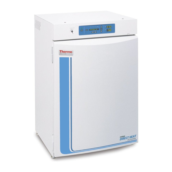
Installation and Start-Up Section 1 Incubator components are described below. Figure 1-1. Model 310 Series Direct Heat Incubator • Outer Door - Reversible to opposite swing, see Section 5 • Inner Door - Reversible to opposite swing, see Section 5 •... -
Page 11: Control Panel Keys, Displays & Indicators
Scroll for Parameters Arrows - Moves the operator through the choices of the selected mode. Inject Indicator - Lights when CO is being injected into the incu- bator. % CO2 Display - Displays CO percentage continuously. Figure 1-2. Control Panel Model 310 Series DH Incubator Thermo Scientific... -
Page 12: Keypad Operation
Section 1 Installation and Start-up Keypad Operation The Model 310 Series direct heat incubator has four basic modes which allow incubator setup: Run, Setpoints, Calibration and System Configuration. Run is the default mode which the incubator will normally be in during operation. -
Page 13: Displays
Stacking the Incubators Caution When stacking incubators, the direct heat incubator must be the top unit. Never stack a water-jacketed incubator on top of a Model 310 Series unit. Warning With incubators in a stacked configuration, do not leave both exterior doors open at the same time. - Page 14 6. Remove the four nylon plugs on the lower back of the upper incubator. 7. Insert the stacking brackets into the slots on the back of the control panel of the bottom unit as shown in Figure 1-6. Figure 1-6. Brackets Installed Thermo Scientific Model 310 Series DH Incubator...
- Page 15 Figure 1-7 shows the support as it would be oriented for right side of chamber. Figure 1-7. Shelf Channels and Ductwork Model 310 Series DH Incubator Thermo Scientific...
- Page 16 2. Remove the plastic coating from the filter, using caution not to touch the filter media. 3. Install the filter as shown in Figure 1-9. Refer to Section 5 for HEPA filter maintenance. Thermo Scientific Model 310 Series DH Incubator...
- Page 17 Electrical Power Caution Connect the incubator to a grounded, dedicated circuit. The power cord connector is the mains disconnect device for the incubator. Position the incubator so the unit can be easily disconnected. Model 310 Series DH Incubator Thermo Scientific...
- Page 18 Water should always be sterilized or treated with a decontaminant, safe for use with stainless steel as well as safe for the product, prior to being introduced into the humidity pan. Thermo Scientific Model 310 Series DH Incubator...
- Page 19 Consult your facility safety officer to ensure that the equipment is installed in accordance with the codes and regulations applicable in your area. 1-10 Model 310 Series DH Incubator Thermo Scientific...
-
Page 20: Incubator Start-Up
See Chart 1-1 for more detail. Setting the Operating Model 310 Series incubators have an operating temperature range of 10°C to 50°C, depending on ambient temperature. The incubator is shipped Temperature from the factory with a temperature setpoint of 10°C. - Page 21 Model 310 Series incubators are equipped with a secondary temperature monitoring system to monitor the air temperature inside the cabinet. This system is designed as a safety device to turn off all heaters in the event of a temperature control failure.
- Page 22 4. Press Enter to save the setpoint. 5. Press the Mode key until the Run indicator lights to go to Run mode or press the right/left arrow keys to go to next/previous parameter. Thermo Scientific Model 310 Series DH Incubator 1-13...
- Page 23 Section 1 Installation and Start-Up 1-14 Model 310 Series DH Incubator Thermo Scientific...
-
Page 24: Calibration
Startup - Allow 12 hours for the temperature in the cabinet to stabilize before proceeding. Already Operating - Allow at least 2 hours after the display reaches setpoint for temperature to stabilize before proceeding. Thermo Scientific Model 310 Series DH Incubator... -
Page 25: Calibrating The T/Cco System
5. Press the Mode key to return to Run or the right/left arrow to go to next/previous parameter. Calibrating the T/C Models 310, 311, 350 and 351 have a thermal conductivity (T/C) CO sensor. Thermal conductivity of the incubator atmosphere is not only System... -
Page 26: Calibrating The Infrared Co System
Start-Up- Allow the temperature and the CO of the cabinet to stabilize at least 12 hours before proceeding. Presently Operating - Allow CO to stabilize at least 2 hours at setpoint before proceeding. Thermo Scientific Model 310 Series DH Incubator... -
Page 27: Calibrating Relative Humidity
5 to 6 minutes. The control panel is locked during this cycle. 7. Press the Mode key to return to Run mode. Calibrating Relative All 310 Series incubators can be equipped with an optional direct readout relative humidity (RH) sensor. This is a readout only of the chamber Humidity relative humidity level. - Page 28 2. With a full humidity pan and stable temperature, the relative humidity in the chamber will be 95%. 3. Using Step 3-5 of the relative humidity sensor adjustment, adjust the display to 95%. This calibration method should be accurate to within 5%. Thermo Scientific Model 310 Series DH Incubator...
- Page 29 Section 2 Calibration Model 310 Series DH Incubator Thermo Scientific...
-
Page 30: Configuration
3. Press up/down arrow to change the access code. 4. Press Enter to save the access code. 5. Press the Mode key to return to the Run mode or right/left to go to next/previous parameter. Thermo Scientific Model 310 Series DH Incubator... -
Page 31: Set A Low Temp Alarm Limit
3. Press the up/down key to toggle the setting ON/OFF. 4. Press Enter to save the setting 5. Press the Mode key to return to Run or the right/left arrow key to go to next/previous parameter. Model 310 Series DH Incubator Thermo Scientific... -
Page 32: Set A Low Co 2 Alarm Limit
3. Press up/down arrow to change the high CO alarm limit. 4. Press Enter to save the high CO alarm limit. 5. Press the Mode key to return to run mode or right/left to go to next/previous parameter. Thermo Scientific Model 310 Series DH Incubator... -
Page 33: Enable Co Alarms To Trip Contacts
3. Press up/down arrow to change the zero number to match the sticker. 4. Press Enter to save the setting. 5. Press the Mode key to return to Run mode or right/left to go to next/previous parameter. Model 310 Series DH Incubator Thermo Scientific... -
Page 34: Set New Span Number For T/C Co Sensors
3. Press up/down arrow to change the RH low alarm limit. 4. Press Enter to save the RH low alarm limit. 5. Press the Mode key to return to Run mode or right/left to go to next/previous parameter. Thermo Scientific Model 310 Series DH Incubator... -
Page 35: Enable Rh Alarms To Trip Contacts
3. Press up/down arrow to toggle the setting ON/OFF. 4. Press Enter to save the setting. 5. Press the Mode key to return to Run mode or right/left to go to next/previous parameter. Model 310 Series DH Incubator Thermo Scientific... -
Page 36: Select Primary Tank W/ Gas Guard Option
3. Press up/down arrow to toggle the setting ON/OFF. 4. Press Enter to save the setting. 5. Press the Mode key to return to Run mode or right/left to go to next/previous parameter. Thermo Scientific Model 310 Series DH Incubator... -
Page 37: Communications Address For Rs485
3. Press up/down arrow to move the RS485 address. 4. Press Enter to save the RS485 address. 5. Press the Mode key to return to Run mode or right/left to go to next/previous parameter. Model 310 Series DH Incubator Thermo Scientific... - Page 38 Section 3 Configuration Thermo Scientific Model 310 Series DH Incubator...
- Page 39 Section 3 Configuration 3-10 Model 310 Series DH Incubator Thermo Scientific...
- Page 40 Section 3 Configuration Thermo Scientific Model 310 Series DH Incubator 3-11...
-
Page 42: Alarms
Alarms Section 4 The Model 310 Series incubator alarm system is shown in the table below. When an alarm is active, the message appears in the LED message center. Pressing Silence disables the audible alarm for the ringback period. However, the visual alarm continues until the incubator returns to a normal condition. -
Page 43: Temp Control Failure Alarm Tmp Cntr Err
Section 4 Alarms Temp Control Failure In addition to other safety features designed into Model 310 Series incubators, a thermostat is also provided to monitor the cabinet’s Alarm TMP CNTR ERR temperature. In the unlikely event of a temperature control failure, the thermostat will turn off all heaters at a cabinet temperature of 65°C,... - Page 44 High CO sensor calibration drift. This will require replacement of the sensor. • Calibration of the CO system to less than 3% actual CO . If this has occurred, contact the Technical Services Department. Thermo Scientific Model 310 Series DH Incubator...
- Page 45 Model 310 Series DH Incubator Thermo Scientific...
- Page 46 Thermo Scientific Model 310 Series DH Incubator...
-
Page 48: Routine Maintenance
If a new blower wheel and scroll are going to be used, discard the old ones. If the old ones are being reused, wash and rinse all parts with disinfectant. Thermo Scientific Model 310 Series DH Incubator... -
Page 49: Cleaning The Cabinet Exterior
Therefore, it is very important to rinse and dry the glass doors after cleaning. Autoclaving the glass doors should be avoided. There is no simple method for repairing corroded glass. In most cases, the glass must be replaced. Model 310 Series DH Incubator Thermo Scientific... -
Page 50: Cleaning The Humidity Pan
The tools required are a Phillips screwdriver, a 1/8” Allen wrench and a flatblade screwdriver. The door reversing procedure takes about 30 minutes. Figure 5-1. Door Swings Thermo Scientific Model 310 Series DH Incubator... - Page 51 Install the nylon screws into the newly exposed holes. 5. Remove the two plastic clips securing the door heater cable. These clips will be rotated 180° when installed on the left lower edge of the door frame. Model 310 Series DH Incubator Thermo Scientific...
- Page 52 Figure 5-3. The insert in the illustration shows the proper Swing (continued) positioning of the clips. Figure 5-3. Rotate Kickplate 7. The incubator and door should look similar to Figure 5-4. Figure 5-4. Unit with Detached Door Thermo Scientific Model 310 Series DH Incubator...
- Page 53 14. Rotate the striker plate 180° from its original position and attach it to the cabinet where indicated. 15. Using a flatblade screwdriver, remove the threaded nylon plugs from the new hinge bracket locations. Install the lower hinge bracket where indicated. Model 310 Series DH Incubator Thermo Scientific...
- Page 54 19. Connect the door heater cable and install the kick plate with the door heater cable on the right side. 20. Installing the outer door onto the hinge pins completes the door reversal procedure. Thermo Scientific Model 310 Series DH Incubator...
-
Page 55: Hepa Filter (Factory Installed Option)
Figure 5-8. Major Components in Electronics Drawer 6. Slide the control panel back in, replace the screws and return the unit to service. If the fuse(s) blow after restoring power to the incubator, contact Technical Services Department. Model 310 Series DH Incubator Thermo Scientific... -
Page 56: Major Components
3. Slide the top about an inch to the rear and lift it off. Note There are small locking tabs in the back which will be bent if the top is lifted off without sliding it first to the back. Thermo Scientific Model 310 Series DH Incubator... -
Page 57: Replacing The Sample Air Filter
1. Connect one end of the sample port filter to the ceiling port. Air Filter 2. Connect the other end of the filter to the back of the blower fan inlet. Figure 5-9. Air Sample Filter 5-10 Model 310 Series DH Incubator Thermo Scientific... -
Page 58: Factory Options
The contacts may also be programmed to trip or not trip on temperature alarms, CO alarms, and RH alarms. See Section 3, Configuration Mode. Figure 6-1. Remote Alarm Output CAUTION Contains Parts and Assemblies Susceptible to Damage by Electrostatic Discharge (ESD) Thermo Scientific Model 310 Series DH Incubator... -
Page 59: Connect Rs485 Interface
Table 6-1 for output specifications of the three boards. For the 0-1V and 0-5V boards, the recording device must supply a load >/= 1000 ohm. For the 4-20mA board, the recording device must supply a load of </= 100 ohm. Model 310 Series DH Incubator Thermo Scientific... - Page 60 * Alternate access to the electronics is to open the outer door and remove the two screws in the upper corners of the cabinet just under the display top. Lifting up the top section, the electronics drawer can be pulled out to the limit of the internal wiring. Thermo Scientific Model 310 Series DH Incubator...
- Page 61 J2 and/or J3 on the analog board. Refer to Figure 6-4. 6. When wiring is completed, slide in the electronics drawer or the replace the sheet metal cabinet top. 7. Replace the screws removed earlier and return the unit to service. Model 310 Series DH Incubator Thermo Scientific...
-
Page 62: Co 2 Gas Guard
Refer to warnings in Section 1 of this manual. The Model 310 Series incubators can be equipped with a built-in Gas Guard system (P/N 190640) that will operate with a CO gas supply. The... -
Page 63: Humidity Readout
10 psig (0.690 bars). Humidity Readout The 310 Series incubators can be equipped with a humidity sensor (P/N 190643) to monitor the relative humidity inside the chamber. The sensor is mounted to the top air duct and provides a signal that is displayed in 1% increments on the control panel. -
Page 64: Uninterruptible Power Supply Connections
Caution Use only factory recommended UPS units which produce a pure sine wave output. Other UPS units could damage the incubator and void the warranty. Typical facility back-up systems will not effect the efficiency of the incubator. Thermo Scientific Model 310 Series DH Incubator... - Page 65 Warning The Uninterruptible Power Supply contains potentially hazardous voltages even when not connected to line voltage. Do not attempt to disassemble UPS as it contains no user-serviceable parts. Repairs must be performed by factory trained service personnel. Model 310 Series DH Incubator Thermo Scientific...
-
Page 66: Specifications
Inlet pressure ....15 psig, ±5 psig Display ..Digital LED, 0.1% increments Thermo Scientific Model 310 Series DH Incubator... - Page 67 Exterior ..26.0” W x 38.5” H x 25.0” F-B Interior ..21.4” W x 26.8” H x 20.0” F-B Model 310 Series DH Incubator Thermo Scientific...
- Page 68 Analog Factory installed: Stock no. 190512 - 4-20mA Digital Factory installed: Stock no. 190523 - RS-485 (Compatible with Model 1535 Alarm Monitor only) Certifications Refer to the Declarations of Conformity at the back of this manual Thermo Scientific Model 310 Series DH Incubator...
- Page 69 Pollution Degree describes the amount of conductive pollution present in the operating environment. Pollution Degree 2 assumes that normally only non-conductive pollution such as dust occurs with the exception of occasional conductivity caused by condensation. Model 310 Series DH Incubator Thermo Scientific...
-
Page 70: Spare Parts
34 position control to display ribbon cable 420097 43VA transformer (230VAC units only) 360213 Pressure switch (Gas Guard option) 250121 Gas valve (Gas Guard option) 190512 4-20mA output board 190543 0-5V output board 190544 0-1V output board Thermo Scientific Model 310 Series DH Incubator... - Page 71 Section 8 Spare Parts Model 310 Series DH Incubator Thermo Scientific...
- Page 72 Section 8 Spare Parts Thermo Scientific Model 310 Series DH Incubator...
- Page 73 Section 8 Spare Parts Assembly Drawing Model: 310/3110 Series CO Incubator 310-202-1-D Rev. 6 Page 1 of 1 Model 310 Series DH Incubator Thermo Scientific...
- Page 74 Section 8 Spare Parts Thermo Scientific Model 310 Series DH Incubator...
- Page 75 Section 8 Spare Parts Model 310 Series DH Incubator Thermo Scientific...
- Page 76 Section 8 Spare Parts Thermo Scientific Model 310 Series DH Incubator...
-
Page 78: Electrical Schematics
Section 9 Electrical Schematics Electrical Schematic Model: 115V Air Jacket Incubator 310-70-0-D Rev. 6 Page 1 of 3 Thermo Scientific Model 310 Series DH Incubator... - Page 79 Section 9 Electrical Schematics Electrical Schematic Model: 115V Air Jacket Incubator 310-70-0-D Rev. 6 Page 2 of 3 Model 310 Series DH Incubator Thermo Scientific...
- Page 80 Section 9 Electrical Schematics Electrical Schematic Model: 115V Air Jacket Incubator 310-70-0-D Rev. 6 Page 3 of 3 Thermo Scientific Model 310 Series DH Incubator...
- Page 81 Section 9 Electrical Schematics Electrical Schematic Model: 311 & 321 Air Jacket Incubator 311-70-0-D Rev. 5 Page 1 of 3 Model 310 Series DH Incubator Thermo Scientific...
- Page 82 Section 9 Electrical Schematics Electrical Schematic Model: 311 & 321 Air Jacket Incubator 311-70-0-D Rev. 5 Page 2 of 3 Thermo Scientific Model 310 Series DH Incubator...
- Page 83 Section 9 Electrical Schematics Electrical Schematic Model: 311 & 321 Air Jacket Incubator 311-70-0-D Rev. 5 Page 3 of 3 Model 310 Series DH Incubator Thermo Scientific...
-
Page 84: Warranty Information
Section 10 Warranty Information Thermo Scientific Model 310 Series DH Incubator 10-1... - Page 85 Section 10 Warranty Information 10-2 Model 310 Series DH Incubator Thermo Scientific...
- Page 86 Thermo Fisher Scientific 401 Millcreek Road Marietta, Ohio 45750 United States www.thermofisher.com...
Need help?
Do you have a question about the 310 and is the answer not in the manual?
Questions and answers