Thermo Scientific 3110 Series Instruction Sheet
Water jacket co2 incubator
Hide thumbs
Also See for 3110 Series:
- Operating and maintenance manual (104 pages) ,
- Manual (11 pages)
Advertisement
Quick Links
Instruction Sheet
Application
Model
7270105 Rev. 1
Preventive Maintenance Kit 2270105
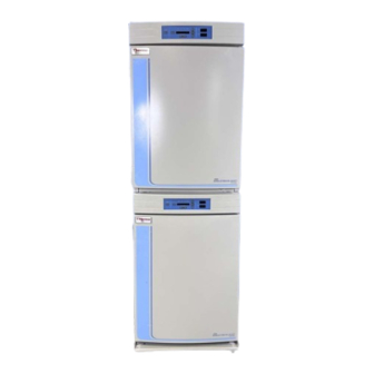
3110 Series Water Jacket CO
(Models 3110, 3111, 3120, and 3121)
Included in this kit (1 each unless specified):
Lithium Grease 1.5 oz.
#6 Silicone Stopper, 1-1/4
Blower Wheel, 3.5 x 1.5 CCW
Blower Wheel, 3.5 x 1.5 CCW "D"
Blower Plate Gasket
CO
Sensor Gasket
2
DCS IR Sensor Plate Gasket 3 x 4
Silicone Grommet, 3/8 x 1/4 (2)
Blind Silicone Grommet, 15/16 (2)
Tools required:
Common hand tools
Caution These procedures should only be performed by qualified
personnel.
▲
Caution Turn unit off and disconnect it from power before beginning any
maintenance or service procedures.
Note There are two blower scroll configurations available in some
instances. Follow the instructions pertaining to your configuration.
Incubator
2
#6 Solid Silicone Stopper
Silicone Hose, 1/4 D x 1/8 W x 1.1 L
Silicone Hose, 1/4 D x 1/16 W x 1 L
Teflon Washer, 0.31 ID x 0.625
HEPA Filter 5.5 x 1.5
Disposable Filter (3)
1/4 Hose x 1/4 Hose Connector
Corrosion Inhibitor, 800mL
▲
▲
Advertisement

Related Manuals for Thermo Scientific 3110 Series


Summary of Contents for Thermo Scientific 3110 Series
- Page 1 Instruction Sheet 7270105 Rev. 1 Preventive Maintenance Kit 2270105 Application 3110 Series Water Jacket CO Incubator Model (Models 3110, 3111, 3120, and 3121) Included in this kit (1 each unless specified): Lithium Grease 1.5 oz. #6 Solid Silicone Stopper #6 Silicone Stopper, 1-1/4 Silicone Hose, 1/4 D x 1/8 W x 1.1 L...
- Page 2 Installation - Note There are several parts included in the kit that will not be used in this application. ▲ Release 1 through 3 1. Locate and remove the access port stopper (Figure 1). Discard. 2. Unfasten the temperature sensor from the clip on the top duct. See Figure 2.
- Page 3 Installation - Release 1 7. Pull down firmly to remove the blower wheel from the motor shaft. Discard the blower wheel. Slide the new blower wheel with the round through 3 (continued) hole up the motor shaft until the wheel is against the shoulder of the shaft.
- Page 4 Installation - Release 1 13. Replace the grommets in the top duct with new ones provided in the kit. through 3 (continued) 14. Install the top duct by feeding the temperature sensor (and RH sensor, if applicable) through the appropriate grommet in the top duct as it is raised to the chamber ceiling.
- Page 5 Installation - Release 4 Note Several parts included in this kit are not used in this application. ▲ 1. Remove the shelves and side duct sheets from the interior of the unit. 2. Remove and discard the access port stopper. See Figure 5.
- Page 6 Installation - Release 4 10. Remove and discard the small white Teflon washer from the motor shaft. (continued) 11. Remove the 6 nuts from the blower plate. Disengage the plate from the chamber ceiling. There may be suction build-up on the plate gasket. Support the blower plate during this process.
- Page 7 Installation - Release 4 18. Install the blower scroll over the blower wheel into the larger end of the keyholes on the blower scroll plate. Turn the scroll to the right to lock (continued) it on. Pull the black lever clip closest to you toward the front of the unit.
- Page 8 Installation - Release 4 24. Install the new access port stopper. (continued) 25. Install the shelves and side duct sheets. 26. Install the new HEPA filter. 27. Plug the incubator in and turn on the power switch. Allow the incubator to run empty for 24 hours and return it to service. Preventive Maintenance Kit 2270105...
- Page 9 Installation - Note Several parts included in this kit are not used in this application. ▲ Release 5, Series II 1. Remove the shelves and the side duct sheets from the interior of the unit. 2. Remove and discard the access port filter assembly.
- Page 10 Installation - Release 5, 10. Remove the blower scroll plate by first pushing the black lever clip farthest from you toward the chamber ceiling. Then turn the blower Series II (continued) scroll plate to the left to disengage it from the alignment keyholes (Figure 11).
- Page 11 Installation - Release 5, 17. Install the new blower wheel with the d-shaped collar onto the motor shaft by aligning the d- Series II (continued) shaped flat sides of each. See Figure 12. Slide the blower wheel onto the motor shaft until the blower wheel rests against the shoulder on the motor shaft.
- Page 12 Installation - Release 5, 20. Check the color of the CO sensor. If it is brass-colored, it is a T/C sensor. If it is white-colored, it is an I/R sensor. Series II (continued) • For replacing the T/C sensor gasket - Remove the two wingnuts and pull the T/C sensor down.
- Page 13 Installation - Release 5, 23. Carefully pull the temperature sensors down until they can be inserted approximately 1 inch into the appropriate holes in the back of the Series II (continued) blower scroll. See Figure 15. Figure 15. Two Scroll Configurations 24.
-
Page 14: Corrosion Inhibitor
The material in this instruction sheet is for information purposes only. The contents and the product it describes are subject to change without notice. Thermo Scientific makes no representations or warranties with respect to this instruction sheet. In no event shall Thermo be held liable for any damages, direct or incidental, arising out of or related to the use of this instruction sheet.
Need help?
Do you have a question about the 3110 Series and is the answer not in the manual?
Questions and answers