Advertisement
Quick Links
Instruction Sheet
7190640 Rev. 7
Qualified Installation of Gas Guard System (CO
, N
)
Application
2
2
Model
310, 370, 3110 and 3950 Series Incubators
Model 310 Series Incubators - Page 2
Model 370 Series Incubators - Page 3
Model 3110 Series Incubators - Page 4
Model 3950 Series Incubators - Page 8
Important When using Nitrogen (N
) , the inlet labels on the back panels
2
of each unit must be covered by the N
labels included in this kit. Refer to
2
the illustrations showing the back panels.
s
Caution Only qualified service personnel should perform this procedure.
s
Advertisement

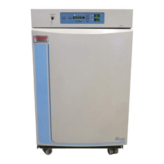
Summary of Contents for Thermo Scientific 310 Series
- Page 1 Qualified Installation of Gas Guard System (CO Application Model 310, 370, 3110 and 3950 Series Incubators Model 310 Series Incubators - Page 2 Model 370 Series Incubators - Page 3 Model 3110 Series Incubators - Page 4 Model 3950 Series Incubators - Page 8...
-
Page 2: Installation
Model 310 Series 1. Turn the incubator off and disconnect it from the power source. Installation 2. Remove the 4 screws from top panel of the unit. Set panel aside. 3. Disconnect vinyl tubing from black hose fitting on the back of the unit identified as CO2 Inlet #1 Tank (Cover this label if using N ). - Page 3 Model 370 Series 1. Turn the incubator off and disconnect it from the power source. Installation 2. Remove the 3 screws from the top panel and set the panel aside. 3. Disconnect vinyl tubing from black hose fitting on the back of the unit identified as CO2 Inlet #1 Tank (Cover this label if using N2).
- Page 4 Model 370 Series 7. Connect the Gas Guard wiring harness as shown. Refer to the wiring color identifications. Installation (continued) 8. Install and secure the top panel with the 3 screws removed previously. 9. Verify the inlet labels on the back of the unit. See Figure 3 when referring to left and right instructions.
- Page 5 Model 3110 Series 6. Slide the electronics tray outward until the main microprocessor board is accessible. Installation (continued) 7. Unplug the electrical connectors along the right side of the micro board. Cut the tie wrap securing the clamp-on ferrite and open it to release the wire cable.
- Page 6 Model 3110 Series 10. Remove the electronics tray completely from the incubator. The wiring cable must be fed through the pass-through port on the right rear Installation (continued) corner of the tray. 11. Disconnect the vinyl tubing from the black plastic hose fitting on the back of the tray identified as CO2 Inlet #1 Tank (Cover this label if using N ).
- Page 7 Model 3110 Series Installation (continued) Figure 10. Electronics Drawer 17. Connect the Gas Guard wiring harness as shown. Refer to the wiring color identifications (COM, NO) as shown in Figure 11. Figure 11. Wiring Color Indentifications QI Gas Guard System...
- Page 8 Model 3110 Series 18. Re-install the electronics tray far enough into the incubator to connect the remaining vinyl hose removed earlier. Installation (continued) Caution In this position, the tray is unstable. Support it at all times. 19. Feed the wiring cable through the pass-through in the right rear corner of the tray and push the tray in far enough to connect the cable to the micro board connectors.
- Page 9 Model 3950 Series 1. Turn the unit off and disconnect it from the power source. Installation 2. Remove the 5 screws from the front of the top cover. Lift and pull outward. Set aside. 3. Referring to Figure 13 on the following page, cut the included vinyl tubing to the lengths specified.
- Page 10 QI Gas Guard System...
- Page 11 The material in this instruction sheet is for information purposes only. The contents and the product it describes are subject to change without notice. Thermo Fisher Scientific makes no representations or warranties with respect to this instruction sheet. In no event shall Thermo be held liable for any damages, direct or incidental, arising out of or related to the use of this instruction sheet.


Need help?
Do you have a question about the 310 Series and is the answer not in the manual?
Questions and answers