Table of Contents
Advertisement
Quick Links
Advertisement
Table of Contents

Subscribe to Our Youtube Channel
Related Manuals for ClearOne Tabletop Controller


Summary of Contents for ClearOne Tabletop Controller
- Page 1 TABLETOP CONTROLLER USER’S MANUAL...
-
Page 2: Important Safety Information
IMPORTANT SAFETY INFORMATION Read the safety instructions before first use of this product. This conferencing phone is not designed for making emergency telephone calls when the power fails. Make alternative arrangements for access to emergency services. • Read and understand all instructions and follow all warnings marked on the product. •... -
Page 3: Chapter 1: Introduction
UNPACKING Carefully place the Tabletop Controller on a level surface. Ensure you have received all items shown in figure 1. Stick-on Labels Tabletop Controller w/6’ cable Documentation on CD for User-de ned Keys Female/Female 40’ cable Y-Adapter Power Supply Null Modem... - Page 4 Technical Services: 800.283.5936...
-
Page 5: Chapter 2: Getting Started
CONNECTING YOUR TABLETOP CONTROLLER 1. Connect the Tabletop Controller to your PC as shown in Figure 2.1. With the Tabeltop Controller connected to your PC, you can launch the Controller Builder application in order to customize the controller to your XAP system. - Page 6 FIGURE 2.2 INSTALLING CONTROLLER BUILDER SOFTWARE Controller Builder is the software you use to customize your Tabletop Controller to your XAP system. Perform the following steps to install the software on your PC: 1. Insert the installation CD into your PC’s CD drive.
- Page 7 USING CONTROLLER BUILDER Upon starting the Controller Builder software, the main screen appears, with the Dial K K eys button depressed (see Figure 2.3). Controller Builder main screen FIGURE 2.3 Controller Builder is composed of the following sections: • Menus and icons •...
- Page 8 > Note: When the Tabletop Controller is connected to a XAP , not only must the baud rate on the XAP be set to either 38,400 or 57,600, but flow control must also be set to OFF--refer to your XAP User’s Manual for instructions on how to set these parameters, if necessary.
- Page 9 • clicking the Help icon (see the illustration to the right). CUSTOMIZING YOUR TABLETOP CONTROLLER WITH CONTROLLER BUILDER Understanding the functions of the key grouping buttons, description fields, command editor, and status editor are best explained by describing the process for customizing the various keys for your controller.
- Page 10 (or devices) with these keys. The following process describes how to customize the room audio keys for your Tabletop Controller: 1. Click the Room A A udio K K eys button. The MUTE, UP (volume up), and DOWN (volume down) keys are outlined in the Controller Builder window.
- Page 11 Customizing room audio keys FIGURE 2.7 Depending on which key you choose to customize, some fields in the Command E E ditor and Status E E ditor at the bottom of the Controller Builder window will be editable and some will not. For example, if you are customizing the MUTE key and choose the MUTE command, then you will only be able to select the device, DID, channel, group, and value for the command, but the results that occur when you press or release the key are defined by default and not editable, as shown by the grayed out fields in the Status...
- Page 12 Customizing room audio keys: mute key with mute command FIGURE 2.8 However, if you choose the MACRO command, then you will be able to not only select the device, DID, and ID of the macro as assigned by XAP , but you will also be able to indicate what you want to occur when that macro runs, or when the key is pressed.
- Page 13 3. The Active T T ext and Inactive T T ext fields, when editable, allow you to input the text (no more than 16 characters) you wish to have displayed on your Tabletop Controller’s display window when the specific state occurs. For example, you might have a macro command running on the XAP 400 that will activate all microphones on channel 1 on that device.
- Page 14 Customizing the User Defined Keys Customizing the user defined keys enables you to use your Tabletop Controller to control a myriad of devices and functions. These keys can be programmed with any of the following commands: GAIN, MACRO, MUTE, PRESET, RAMP, SPEEDDIAL, STRING, or .
-
Page 15: Chapter 3: Using The Tabletop Controller
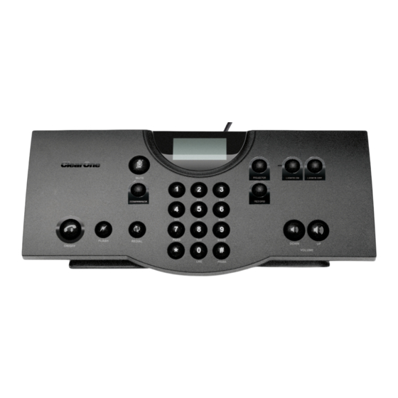
CHAPTER 3: USING THE TABLETOP CONTROLLER TO ANSWER A CALL 1. Press on the controller to answer the call. When there is an incoming call, you will see “ringing” on the. controller display and the phone icon flashes. TO MAKE A CALL 1. -
Page 16: To Adjust The Speaker Volume
TO SEND A FLASH SIGNAL 1. Press to use call transfer, call waiting, or conference calling. > Note: This feature is dependent on your PBX service or local phone service. Refer to your PBX vendor or local telephone service for details. TO ADJUST THE SPEAKER VOLUME Press to increase the volume. -
Page 17: Chapter 4: Maintenance
CREATING A CUSTOM CABLE If you wish to extend the cable length from the Tabletop Controller to the XAP to the full 150’-certified length, you will need to create a custom cable of this length using CAT-3 or better cable. You CANNOT use a standard telephone cable because the pinouts in a standard telephone cable connector are not compatible with the Y- adapter supplied with your Tabletop Controller. - Page 18 Technical Services: 800.283.5936...
-
Page 19: Chapter 5: Appendix
Input: 100 to 240 VAC, 50-60 Hz, 0.5 A Output: 12 VDC, 0.83 A RS-232 CONTROL PORT DB9 Female 38,400/57,600 baud rate: 8 bits, 1 stop, no parity Flow Control: None MAXIMUM DISTANCE FROM CONTROLLER TO MIXER 150’ CAT 3 Cable MODELS 910-151-890 Tabletop Controller Chapter 5: Appendix... -
Page 20: Serial Commands
SERIAL COMMANDS The XAP accepts serial commands through the serial port or the expansion bus. RS-232 serial port protocol is 38,400 or 57,600 baud; 8 bits, 1 stop bit, no parity. CONVENTIONS The following typographic conventions are used in this document to describe the different serial commands. Use the Command structure section and the examples as a guide when creating your serial commands. -
Page 21: Type And Device Ids
Groups and channels FIGURE 5.1 TYPE AND DEVICE IDS Type I I D Unit t t ype Device I I D r r ange XAP 800 XAP TH2 XAP 400 Chapter 5: Appendix... - Page 22 METER TYPE DEFINITIONS Meter type definitions FIGURE 5.2 SERIAL COMMAND ERROR CODES Error n n umber Text m m essage Explanation/Solution Memory error The box is out of internal memory. Power cycle the box. No command found A command was not found in the string. Unknown command A command was executed on a different device type that this box cannot display.
- Page 23 XAP SERIAL COMMANDS Command Function GAIN Changes/reports gain for in, out, or process MACRO Executes macro or reports last macro executed MUTE Sets/reports mute status PRESET Executes preset or reports last executed preset RAMP Starts/stops the gain ramp for an input, output, or assignable processing block SPEEDDIAL Dials one of ten numbers on the telco channel STRING...
-
Page 24: Preset - Preset Execution/Reporting
MUTE - MUTE This command selects/reports the setting of mute on input, output or processing channels. Command form: DEVICE M M UTE <Channel> <Group> [Value] Argument d d etails Name Description Device 0–7 or * to select all units MUTE Command form Channel See Groups and Channels in your XAP User’s Manual... - Page 25 RAMP - RAMP GAIN ADJUSTMENT This command starts/stops the gain ramp for an input, output, or assignable processing block. There is no query for this command. Command form: DEVICE R R AMP <Channel><Group><Rate>[Target] Argument D D etails Name Description Unit Device 0–7 or * to select all units RAMP...
-
Page 26: String - String Execution
STRING - STRING EXECUTION This command sends the specified string out the serial port. Command form: DEVICE S S TRING [ID] Argument D D etails Name Description Device 0–7 or * to select all units STRING Command 0 – 7 Null to query last string in text Example: #51 S S TRING 3 3 On XAP 800 unit 1 (#51), the STRING programmed into location 3 will be... -
Page 27: European Compliance
Operation is subject to the following two conditions: (1) This device may not cause interference, and (2) This device must accept any interference including interference that may cause undesired operation of the device. Changes or modifications not expressly approved by ClearOne Communications could void the user's authority to operate the equipment. -
Page 28: Warranty
Managing Director - EMEA North Title Title WARRANTY ClearOne Communications, Inc. (Manufacturer) warrants that this product is free of defects in both materials and workmanship. For warranty information and coverage, refer to the ClearOne website at www.clearone.com. ClearOne Communications Inc.
Need help?
Do you have a question about the Tabletop Controller and is the answer not in the manual?
Questions and answers