
Subscribe to Our Youtube Channel
Related Manuals for Inficon Cygnus 2


Summary of Contents for Inficon Cygnus 2
- Page 1 Cover Page Cygnus ® Thin Film Deposition Controller PN 074-545-P1H...
- Page 2 All other brand and product names are trademarks or registered trademarks of their respective companies. Disclaimer The information contained in this Operating Manual is believed to be accurate and reliable. However, INFICON assumes no responsibility for its use and shall not be liable for any special, incidental, or consequential damages related to the use of this product.
- Page 3 Declaration Of Conformity Page 1...
- Page 4 Seller product was not designed nor against any defects due to plans or instructions supplied to Seller by or for Buyer. This manual is intended for private use by INFICON® Inc. and its customers. Contact INFICON before reproducing its contents.
-
Page 5: Table Of Contents
How To Contact INFICON ........ - Page 6 Cygnus 2 Installation ........
- Page 7 Cygnus 2 Operating Manual Displays ........... . 3-5 3.3.1...
- Page 8 Trend Analysis ..........3-40 3.5.11.1 Cygnus 2 Parameters Associated with the Trend Analysis Feature ..3-40 Chapter 4 Sensor and Source Set-Up Sensor Set-Up Introduction .
- Page 9 Cygnus 2 Operating Manual Special Material Parameter Features ......5-17 5.2.1 Skip Deposit ..........5-17 5.2.2...
- Page 10 Cygnus 2 Action List........
- Page 11 Remote Material Action ........9-46 9.4.33 Cygnus 2 Communications Examples ......9-48 9.4.33.1 General Command Packet Format.
- Page 12 Troubleshooting Cygnus 2 ........13-12...
- Page 13 Cygnus 2 Operating Manual 13.8.1.1 Measurement System Diagnostic Procedure ..... . 13-27 13.8.1.2 Feedthrough Or In-Vacuum Cable Diagnostic Procedure ........13-28 13.8.1.3...
-
Page 14: Introduction And Specifications
Introduction and Specifications 1.1 Introduction Cygnus 2 is a closed loop process controller designed for use primarily in physical vapor deposition. Cygnus 2 monitors and/or controls the rate and thickness of the deposition of thin films. Deposition rate and thickness are inferred from the frequency change induced by mass added to a quartz crystal. -
Page 15: Cygnus 2 Safety
When using this manual, please pay attention to the Notes, Cautions, and Warnings found throughout. For the purposes of this manual they are defined as follows: NOTE: Pertinent information that is useful in achieving maximum Cygnus 2 efficiency when followed. CAUTION Failure to heed these messages could result in damage to Cygnus 2. -
Page 16: General Safety Information
1.2.3 Earth Ground Cygnus 2 is connected to earth ground through a sealed three-core (three-conductor) power cable, which must be plugged into a socket outlet with a protective earth terminal. Extension cables must always have three conductors including a protective earth terminal. -
Page 17: Main Power Connection
Cygnus 2 Operating Manual 1.2.4 Main Power Connection WARNING - Risk Of Electric Shock This Cygnus 2 has line voltage present on the primary circuits whenever it is plugged into a main power source. Never remove the covers from Cygnus 2 during normal operation. -
Page 18: How To Contact Inficon
If you deliver a package to INFICON without an RMA number, your package will be held and you will be contacted. This will result in delays in servicing your Cygnus 2. Prior to being given an RMA number, you may be required to complete a Declaration Of Contamination (DOC) form if your sensor has been exposed to process materials. -
Page 19: Cygnus 2 Specifications
Cygnus 2 Operating Manual 1.4 Cygnus 2 Specifications 1.4.1 Measurement Crystal Frequency ....6.0 MHz (new crystal) to 4.5 MHz Internal Precision ..... ±0.0035 Hz over 100 ms sample for... -
Page 20: Cygnus 2 Features
Cygnus 2 Operating Manual 1.4.3 Cygnus 2 Features 1.4.3.1 Recipe Storage and Datalogging USB Memory Device 1.4.3.2 Sensor Parameters (Sensor) Shutter Output ....0 to 38 Sensor Type . -
Page 21: Material Parameters
Cygnus 2 Operating Manual 1.4.3.4 Material Parameters 6 Materials can be specified and given unique names (15 character max.). Density ......0.100 to 99.999 g/cc Z-ratio . - Page 22 Cygnus 2 Operating Manual Time Limit (in Deposit) ....00:00 to 99:59 min:s Rate Filter Time ..... . 0.1, 0.4, 1.0, 4.0, or 10.0, 20.0, 30.0 s Time Power Averaging Time .
-
Page 23: General Global Parameters
Cygnus 2 Operating Manual 1.4.3.5 General Global Parameters Date Format ......DDMMYYYY or MMDDYYYY LCD Dimmer Time ....0 for Always On or # of Minutes till Off 0 to 99 minutes Graph Scale . -
Page 24: Display
Cygnus 2 Operating Manual 1.4.4 Display Type/Color/Size ..... . LCD/Color/TFT/7 inch diagonal Dimming Feature ..... Always Full on or Full on when in use. -
Page 25: Dac Outputs
Cygnus 2 Operating Manual 1.4.5 DAC Outputs Quantity and Type ....6 with BNC, 6 optional with 15 pin miniature D-sub providing analog outputs for Rate and Thickness. -
Page 26: Logic Processing
Hierarchy ......Statements evaluated in numerical order at 10 Hz any time Cygnus 2 is Partitioning . -
Page 27: Remote Communications
1.4.8 Remote Communications RS232C Serial Port ....Standard; INFICON binary protocol Baud Rates......115,200, 57,600, 38,400, 19,200, 9,600 Ethernet . -
Page 28: Operating Environment
Cygnus 2 Operating Manual 1.4.11 Operating Environment Usage......Indoor only Temperature ......0 to 50°C (32-122°F) Humidity . -
Page 29: Weight
1.6 Parts and Options Overview 1.6.1 Base Configurations Cygnus 2 Control Unit ....781-500-G11 North America, 781-500-G12 Europe Ship Kit ......781-020-G1 North America, 781-020-G2 Europe Operating Manual on CD ROM . -
Page 30: Pre-Installed Options Or Spares
Function:Power Increase/Decrease/Stop/Switch Crystal 1.6.4 Oscillator Packages Cygnus 2 Oscillator, 15 ft. and 6 in. cable . . pkg. . . 781-611-G15 Cygnus 2 Oscillator, 30 ft. and 6 in. cable pkg..781-611-G30 Cygnus 2 Oscillator, 50 ft. and 6 in. cable pkg..781-611-G50 Cygnus 2 Oscillator, 100 ft. -
Page 31: Replacement Cables
6 in Cygnus 2 Unit to Oscillator Cable 15 ft ..600-1261-P15 Cygnus 2 Unit to Oscillator Cable, 30 ft ..600-1261-P30 Cygnus 2 Unit to Oscillator Cable, 50 ft . -
Page 32: Initial Power-On Verification
Cygnus 2 Operating Manual 1.7 Initial Power-On Verification A preliminary functional check of Cygnus 2 can be made before formal installation. It is not necessary to have sensors, source controls, inputs or relays connected to do this. For more complete installation information, see... - Page 33 Cygnus 2 Operating Manual Confirm that AC line voltage is supplied and proper for Cygnus 2. Confirm that the back panel (main) AC switch is in the ON position. Press the ON/STBY button on the front panel. A green pilot light should be illuminated next to the power switch.
-
Page 34: Installation And Interfaces
The choice of sensor type must be dictated by the process, the deposition material and the physical characteristics of the process chamber. General guidelines for each sensor type produced by INFICON are outlined in the Sensor Data Sheets on www.inficon.com website. - Page 35 Cygnus 2 Operating Manual Figure 2-1 Typical installation Mounting Bracket Coax Cable (Routed with Water Tubes) Sensor Shutter Brazing Adapters Source to Sensor Customer Supplied 10" Minimum Cajon Coupling Source Shutter Source Pneumatic Actuator Source Controller Water In Water Out...
- Page 36 Cygnus 2 Operating Manual Generally, install the sensor as far as possible from the evaporation source (a minimum of 10 in. (25.4 cm) is recommended) while still being in a position to accumulate thickness at a rate proportional to accumulation on the substrate.
-
Page 37: Cygnus 2 Installation
Cygnus 2 Operating Manual 2.1.3 Cygnus 2 Installation Cygnus 2 is designed to be rack mounted. It may be also used on a table. Cygnus 2 is forced-air cooled, with the air flow exiting the rear of Cygnus 2 for clean room convenience. -
Page 38: Connections To Earth Ground
There are two required earth ground connections: The earth ground connection on Cygnus 2 is a threaded stud with a hex nut. Connect a ring terminal to the ground strap, thus allowing a good connection and easy removal and installation. This connection must be made at installation. -
Page 39: Minimizing Noise Pickup From External Cabling
Vacuum System 2.2.3 Minimizing Noise Pickup from External Cabling When a Cygnus 2 is fully integrated into a deposition system, there can be many wire connections, each a potential path for electrical noise to reach the inside of Cygnus 2. The likelihood of these wires causing a problem can be greatly diminished by adhering to the following guidelines. -
Page 40: Connecting The Controller
Cygnus 2 is initially powered by AC line current. The line voltage provided in your facility must be within the voltage range shown in section 1.4.10, Power, on page... -
Page 41: Source Control Connection
2.3.2.1 Source Control Connection Six Digital-to-Analog (DAC) outputs are provided as standard equipment with Cygnus 2. These standard 6 DAC channels with BNC connectors and six optional DAC outputs on a 15 pin sub-D connector may be programmed for Source control or chart recorder functions as desired. -
Page 42: I/O Expansion Options
Cygnus 2 Operating Manual 2.3.2.4 I/O Expansion Options One I/O Relay module is included as standard equipment with Cygnus 2 and is used to interface with other machinery of the vacuum system. It can control components such as heaters, rotators or shutters through its 8 relays. It can respond to external instructions through its 14 isolated input lines. - Page 43 Cygnus 2 Operating Manual Table 2-3 Input/Relay pin connections I/O Board #1 I/O Board #2 Relay # Pins Relay # Pins Input # Input # 7, 6 7, 6 9, 8 9, 8 11, 10 11, 10 13, 12 13, 12...
-
Page 44: Rs-232C Communications
2.3.2.5 RS-232C Communications RS-232C serial communications is included in Cygnus 2 as standard equipment. It can be used to remotely control or monitor Cygnus 2. An industry standard 9-pin D-Sub connector is required for the host computer side connection. Depending on the computer source, all connections may not be necessary. -
Page 45: Isolated +24 V (Dc) Supply
2.3.2.6 Isolated +24 V (dc) Supply An isolated +24 V (dc) power supply is available on a 9-pin D-Sub connector on the Cygnus 2 back panel. This supply is rated for 1.75 Amps maximum. The pin assignments for this connector are shown in Table 2-5. -
Page 46: Operation
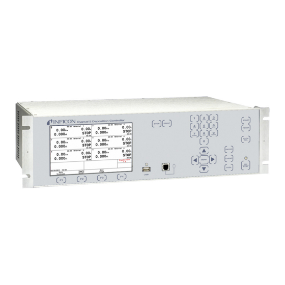
Cygnus 2 Operating Manual Chapter 3 Operation 3.1 Front Panel Controls Operational controls for Cygnus 2 are located on the front panel, see Figure 3-1. Figure 3-1 Cygnus 2 front panel LCD Screen Provides graphical displays, set-up menus, status and error messages. - Page 47 An array of five keys used to move the display cursor either up, down, left or right. The MENU key is used to navigate through the Cygnus 2 displays. The keys auto-repeat; the cursor will continue to move as long as the key is held down.
-
Page 48: Rear Panel Interfaces
Cygnus 2 Operating Manual 3.2 Rear Panel Interfaces Interfaces for Cygnus 2 are located on the rear panel, see Figure 3-2. Figure 3-2 Cygnus 2 rear panel Ground Stud Refer to section 2.2.2, Connections to Earth Ground, on page 2-5. - Page 49 Provides recorder output for six channels (15 pin miniature D-sub connector). Outputs are programmable for recorder function. 13 Fan Outlet Exhaust opening for the Cygnus 2’s miniature fan; Do not block! 14 24-Volt Supply (standard) Provides three 24 V (dc) supplies rated at 1.75 Amps. See Table 2-5 on page 2-12.
-
Page 50: Displays
Cygnus 2 Operating Manual 3.3 Displays Cygnus 2 has many display screens for monitoring and programming processes. The five main types of displays are: Operate, Sensor, Source, Material, and General. To move from one display to another, use the cursor and MENU keys. -
Page 51: Operate
Cygnus 2 is in Test mode. Status messages are displayed as long as a status is true. They are put up and taken down as the condition that set them changes. - Page 52 Cygnus 2 Operating Manual Operate Display Description Rate Thickness Power Level State of Material State Timer Material Timer Material Being Deposited Source Number In Use Sensor Number In Use 10 Crystal Position In Use 11 Graphical Display of Rate Deviation or Power...
-
Page 53: Sensor Information
Cygnus 2 Operating Manual Figure 3-5 6 Material display 3.3.3 Sensor Information 3.3.3.1 Sensor Information Rate/Xtal Display Description NOTE: N/A (not available) will be displayed in these fields for disabled features or for Sensors not in use. Figure 3-6 Rate/Xtal display... - Page 54 Q Counts, or Clear Failed Crystals is pressed, that function will be performed on the Sensor indicated by the box cursor if Cygnus 2 is in Ready, Stop or all active Materials are in Idle. Text will only be shown for installed cards, unless you are in TEST.
-
Page 55: Crystal Life And Starting Frequency
On the Sensor Information RATE/XTAL display, crystal life is shown as a percentage of the monitor crystal’s frequency shift, relative to the 1.50 MHz frequency shift allowed by Cygnus 2. This quantity is useful as an indicator of when to change the monitor crystal to safeguard against crystal failures during deposition. -
Page 56: Sensor Information Type/Freq Display Description
Cygnus 2 Operating Manual taken on the Sensor indicated by the box cursor if Cygnus 2 is in Ready, Stop or all active Materials are in Idle. Failed crystal numbers are shown in the Failed column under Crystal. Generic Sensor Status showing which crystals are good and which are failed relative to the current position is displayed in the bottom region of the table. -
Page 57: Test Xiu
Auto-Z value (prior to failure) is used for thickness calculations for this Sensor. Cygnus 2 determines to use Matl or Sens depending on the frequency of the fundamental resonance. If the fundamental frequency closely matches the last valid fundamental frequency prior to Auto-Z failure, Cygnus 2 will use the Sens value. -
Page 58: Sensor Screen
Cygnus 2 Operating Manual 3.3.4 Sensor Screen From the main MENU display, placing the cursor on Sensor and pressing MENU brings up the Sensor display. The Sensor Overview display, see Figure 3-8, shows the current configuration for all six Sensors. -
Page 59: Source
Cygnus 2 Operating Manual 3.3.5 Source The Source Overview display, see Figure 3-9, shows the current configuration for all six Sources. Figure 3-9 Source overview display Once the right cursor key has been used to move to one of the six Sources, the Select Source function key will appear. -
Page 60: Material
Cygnus 2 Operating Manual 3.3.6 Material This display is organized into eight sub pages accessible thru the Select Menu described below. Chapter 5, Material Set-Up for programming details and screen displays. 3.3.6.1 Overview Page The Material Overview display, see Figure 3-10, shows all 6 available Materials. -
Page 61: Sensor Page
Cygnus 2 Operating Manual 3.3.6.3 Sensor Page The Material Sensor page, see Figure 3-11, allows selecting the Tooling factor. Other choices will be shown according to the Sensor Type. If the Sensor is a CrystalTwo, the Tooling factor for the secondary crystal can be specified. In the case of a multi-position rotary sensor head, the range of crystal positions to use can be specified. -
Page 62: Lib A-Hf, Lib Hf-Sc, Lib Sc-Z Sub-Displays
Cygnus 2 Operating Manual 3.3.6.6 Lib A-Hf, Lib Hf-Sc, Lib Sc-Z Sub-Displays These three libraries allow convenient selection of a Material by its chemical formula along with the correct density and Z-Ratio values. Cursor to a Material formula, then press F1 Define Material to select that Material. The Material/Source display will be shown where the remaining parameters can be entered. -
Page 63: Comm Page
Cygnus 2 Operating Manual 3.3.7.3 Comm Page Datalogging of crystal data is enabled here and RS232 and optional Ethernet parameters are entered. Datalog Xtal Info RS232 / Baud Rate/ Protocol Ethernet / IP Address/ Net Mask section 6.4, COMM Page Parameters, on page 6-3. -
Page 64: Digital I/O
Cygnus 2 Operating Manual 3.3.8 Digital I/O The Digital I/O displays show configuration of all inputs, see Figure 3-13, and outputs, see Figure 3-14, and allows configuring inputs and outputs on the three possible I/O boards. See Chapter 7, Digital I/O for programming details. -
Page 65: Logic
Cygnus 2 Operating Manual 3.3.9 Logic 100 logic statements can be set up. Logic statements are evaluated sequentially, 10 times per second, while Cygnus 2 is powered up. Chapter 8, Logic Statement Set-Up for programming details. 3.3.10 Maintenance The Maintenance display is organized into two subscreens: Source Maint(enance) and Sys(tem) Status. - Page 66 Cygnus 2 Operating Manual Figure 3-15 Process state diagram Figure 3-16 Normal Sequence Alternate Sequence Hand denotes key press 3 - 21...
- Page 67 Cygnus 2 Operating Manual 3 - 22...
-
Page 68: State Descriptions
STATUS COMM ENCODES Source Sensor Shutter Shutter 1. READY Cygnus 2 will accept a START command. Inactive Inactive 2. CRUCIBLE SWITCH During this state, the crucible turret is being Inactive Inactive (Crucible Sw) moved from its current position to the one called out for the given Material. - Page 69 Cygnus 2 Operating Manual Table 3-2 State descriptions (continued) STATE CONDITION RELAY CONTACT REMOTE STATUS COMM ENCODES Source Sensor Shutter Shutter 13. TIME POWER Crystal failed; Source maintained at average Active Inactive control power and average rate prior to crystal failure. [Failure Actions] 14.
-
Page 70: Special Features
The Material’s display is frozen at the last thickness value. NOTE: In STOP Cygnus 2 will accept a START provided a valid crystal is available for the Material being started. 3.5 Special Features Cygnus 2 has several special features to enhance the performance of the instrument. -
Page 71: Xtaltwo (Crystaltwo)
Power-up initialization is performed on a dual sensor to verify that the secondary crystal is good. If a crystal fail occurs while in Deposit, Cygnus 2 will switch to the second crystal and continue. The Failed Crystal list can be cleared while in Deposit by pressing the F4 function key on the Sensor Information screen with the cursor positioned on the appropriate Sensor number. -
Page 72: Xtalsix (Crystalsix)
Cygnus 2 pulses again and rechecks the position. If position 1 is not detected or after 13 pulses of the wrong value, Cygnus 2 reports a Crystal Sw Fail message. In that case, all crystals are also marked as failed, except for current position status. -
Page 73: Generic Sensor Crystal Switching
After a crystal switch sequence, Cygnus 2 will attempt to find the resonant frequency for the crystal in this position. If Cygnus 2 does not find a good resonant frequency for this crystal, it will again pulse the Crystal Switch Output and attempt to find a resonant frequency at the next position. -
Page 74: Auto-Z
The selection of a particular crucible for a Material is defined in the Material page. 3.5.3 Auto-Z The Auto-Z feature of Cygnus 2 automatically determines the Z-Ratio of a crystal. This feature is enabled on the SENSOR page of the SENSOR screen. For the theory behind Auto-Z, see section 14.1.6, Auto-Z Theory, on page... - Page 75 As mass is deposited onto the crystal, the oscillation is damped. This damping may be severe enough that the resonance can no longer be determined. If Cygnus 2 loses the ability to measure the first anharmonic frequency, but is still able to determine the fundamental frequency, the “unable to Auto-Z” message is displayed.
-
Page 76: Rate Watcher
2. The Handheld Controller serves as a wired remote to manually control power, switch crystals and produce a STOP. The Handheld Controller is attached to Cygnus 2 with a modular plug to the front panel. Power is affected only when in Manual mode by moving the POWER/STOP switch laterally. -
Page 77: Determining Soak Power With The Handheld Controller
Test mode is active. 3.5.6.1 Standard or Time Compressed This Cygnus 2 contains a software-controlled test mode which simulates actual operation. In Time Compressed mode, all Material times are sped up so that a long process can be simulated in one tenth of the time. The purpose of the test mode is to verify basic operation and to demonstrate typical operation. -
Page 78: Usb Storage Device
The parameter set may be stored under a new or existing filename and retrieved from an existing file. A file containing the Cygnus 2 parameter set is referred to as a configuration file. Datalog information will be saved only if the USB Datalog Format setting in the Datalog page of the USB Storage screen is set to Comma or Page. -
Page 79: Lock And Access Codes
Cygnus 2 Operating Manual 3.5.8 Lock and Access Codes Cygnus 2 has several forms of protection to prevent unauthorized changing of parameters. Refer to the General setup section for a description of parameter and Program lock codes and the File Access Code. In addition, a method of locking the entire display is available through the remote communications. -
Page 80: Datalog
Cygnus 2 Operating Manual 3.5.9 Datalog When a Source Shutter closes, an end of deposit occurs, or following a Stop, a set of data will be collected. The data gives the user a snap shot of the layer data as the layer completed. -
Page 81: Datalog Contents
Cygnus 2 Operating Manual 3.5.9.1 Datalog contents: The following values make up the data in the datalog. The data is sent in ASCII strings when the RS-232 port is set for data logging. The data is also saved as ASCII strings in the datalog files. The ASCII strings are made up of the labels and values in the following list. - Page 82 Cygnus 2 Operating Manual NOTE: If Data Log Xtal Info Parameter is set to Yes, the following Crystal History will be sent for each Sensor, see Table 3-3. The Crystal history contains the history of every crystal in every Sensor used in the Material. In the Remote status command SL17 #, the crystal history for all twelve crystals in all six Sensors is returned.
-
Page 83: Page Format Ascii Example
Cygnus 2 Operating Manual 3.5.9.2 Page Format ASCII Example: To USB Storage Device and/or RS-232 Protocol Dlog Page for Material #1. DATE: 09/16/2010 TIME: 09:13 LAYER #: MATERIAL NAME: LAYER TIME: 01:02 DEPOSITION TIME: 01:02 THICKNESS: 2.504 kAng AVE. AGG. RATE: 40.0 Ang/S... -
Page 84: Comma Format Ascii Example To Usb Storage Device
Cygnus 2 Operating Manual 3.5.9.3 Comma Format ASCII Example to USB Storage Device: "09/15/2010","14:04", 1,"ONE ","00:15","00:15", 0.600, 40.0, 0.0, 0.0, 0.0,"Post Deposit ","TIME POWER" If Datalog Xtal Info was set to Yes, Crystal History consisting of Sensor #, Crystal#, with the crystal data for twelve crystals is sent as displayed below. -
Page 85: Dac Monitoring
0 indicates there is not a DAC identified with this particular Material. Values 1 through 6 correspond to the six DAC BNC outputs on the back of the Cygnus 2 labeled DAC 1 to DAC 6. DAC outputs 7 to 12 require the optional DAC outputs card. -
Page 86: Sensor And Source Set-Up
The basic Cygnus 2 has one sensor measurement board with two Sensor channels, identified as CH1 and CH2 on the Cygnus 2 back panel and as Sensor # 1 and Sensor # 2 on the display screens. Two more sensor measurement boards can be added to support up to six sensors. -
Page 87: Sensor Parameters
Cygnus 2 Operating Manual Figure 4-2 Sensor parameter editing 4.1.2 Sensor Parameters SENSOR TYPE ....Single (0), XtalTwo (1), XtalSix (2), Xtal12 (3), Generic (4). Press the TOGL key to move through the choices. - Page 88 DAC used with this Sensor. Values 1 through 6 correspond to the six DAC BNC outputs on the back of the Cygnus 2 labeled DAC 1 to DAC 6. DAC outputs 7 to 12 require the optional DAC output card.
-
Page 89: Source Set-Up Introduction
Cygnus 2 Operating Manual 4.2 Source Set-Up Introduction Cygnus 2 provides the capability to configure the six Source control channels. Each Source control channel is treated as an individual device. Source Set-Up is initiated by moving the cursor to the Source heading on the Main Menu and pressing MENU. -
Page 90: Source Parameters
Values range from 0 to 12, with 0 indicating there is no DAC identified with this particular Source. Values 1 through 6 correspond to the six DAC BNC outputs on the back of the Cygnus 2 labeled DAC 1 to DAC 6. DAC outputs 7 to 12 require the optional DAC outputs card. - Page 91 TURRET FEEDBACK ... Yes (1), No (0) Some turret source indexers provide feedback to signify when the turret is in the proper position. This parameter allows Cygnus 2 to accept this input and respond accordingly. Parameter entry may be either Yes or No. Yes indicates that Turret Feedback is expected and the Turret Input parameter is displayed on the screen.
-
Page 92: Dac Output Selection Rules
The six standard DAC outputs, DAC 1 to DAC 6, located on the back of the Cygnus 2 and the six optional DAC outputs, DAC 7 to DAC 12, may be used for rate control or to record rate, thickness and rate deviation. Since these outputs can be set up for different functions, certain rules apply. -
Page 93: Material Set-Up
Material Set-Up 5.1 Introduction Cygnus 2 can store definition parameters for up to 6 Materials. Any Material that is to be used must be defined. Materials can be defined by referencing the internal Material Library containing more than two hundred cataloged materials and by completing a series of parameter entries at the front panel. -
Page 94: Material Definition
Cygnus 2 Operating Manual 5.1.2 Material Definition Figure 5-2 Material library A - Hf display The three Material Libraries—Lib A - Hf, Lib Hf - Sc and Lib Sc - Z—provide an alphabetic list of materials by chemical name along with their density and Z-Ratio. -
Page 95: Material Source
Cygnus 2 Operating Manual 5.1.3 Material Source Page Parameters Figure 5-3 Material source screen MATERIAL NUMBER ... 1 to 6 Change the number to edit or create a different Material. - Page 96 Cygnus 2 Operating Manual CONTROL LOOP ....NonPID (0), PI (1), PID (2) The bracketed value is used for changing the setting via the remote communications commands. This parameter establishes the control loop algorithms pertaining to either a slow responding source or a fast responding source.
- Page 97 Cygnus 2 Operating Manual DEAD TIME ....0.010 to 9999.99 s This value is defined as the time difference between a change in % power and the start of an actual change in rate.
- Page 98 Values 1 through 6 correspond to the six DAC BNC outputs on the back of the Cygnus 2 labeled DAC 1 to DAC 6. DAC outputs 7 to 12 require the optional DAC outputs card. The default value is zero for...
-
Page 99: Material Sensor Parameters Page
Cygnus 2 Operating Manual 5.1.4 Material Sensor Parameters Page Figure 5-6 Material sensor page MATERIAL NUMBER ... 1 to 6 Change the number to edit or create a different Material. - Page 100 Cygnus 2 Operating Manual If the Sensor type is XtalSix (CrystalSix) or Xtal12 (Crystal12) XTAL POSITION FIRST . . . 0 to 6 (12 for Xtal12) XTAL POSITION LAST..0 to 6 (12 for Xtal12) If all available positions are to be used for this Material, set both values to 0.
- Page 101 Quality Percent, the Counts value is decremented. Counts are not allowed to have negative values. If Counts exceeds the value programmed, Cygnus 2 will automatically crystal switch, complete the process on TIME-POWER, POST DEP, or STOP the process. The rate deviation is computed on each individual rate measurement during the deposit phase, that is, every 100 ms.
-
Page 102: Pre/Post Screen Deposit
This parameter is usually set to the power level at which the source material just begins to glow. Cygnus 2 ramps the power level from zero to Pre-Cond Soak Power linearly over the time period Pre-Cond Rise Time. The default value is 0. - Page 103 This parameter is usually set to the power level at which the material just begins to melt. Cygnus 2 ramps the power level from zero or Precon Soak level if programmed to Soak Power 1 linearly over the time period Rise Time 1. The default value is 0.
- Page 104 Source control power for the time interval programmed in Control Delay Time. During Control Delay, the Source and Sensor shutters are activated. Both (3): Cygnus 2 will first enter a shutter delay state followed by the control delay interval. 5 - 12...
-
Page 105: Post Deposit Parameters
CONTROL DELAY TIME ..00:00 to 99:59 This is the time interval for Cygnus 2 to be held in the Control Delay state. The parameter is displayed only if the Delay Option chosen is Control or Both. The default value is 00:00. -
Page 106: Deposit
Cygnus 2 Operating Manual IDLE POWER ....0.0 to 99.99% This value is the power level at which the Source is maintained after the DEPOSIT state (or after Feed state if one is set up). - Page 107 Cygnus 2 Operating Manual TIME LIMIT ....00:00 to 99:59 min:s This is the deposition time at which the Time Limit is triggered. This time begins to accumulate at the start of the Deposit state.
- Page 108 Cygnus 2 Operating Manual ION ASSIST DEPOSIT ..No (0), Yes (1). Sets the logic condition to True if Yes (1) is selected and the Deposit state is entered. Default is No (0).
-
Page 109: Special Material Parameter Features
Rate 1 to New Rate 2. The default value is 00:00. 5.2 Special Material Parameter Features 5.2.1 Skip Deposit If the Final Thickness is set to 0.000 kÅ, Cygnus 2 will skip the DEPOSIT State. State processing will go directly to the post-Deposit parameter state from the last pre-Deposit state. - Page 110 Cygnus 2 Operating Manual If the deposition rate meets the RateWatcher Accuracy requirement for the duration of the Acceptance Window Time, the sensor shutter is closed and RateWatcher enters Hold phase for the RateWatcher Time duration. Finally, after the Hold Time has elapsed, RateWatcher will enter a 5 second Delay phase.
-
Page 111: General Parameters
Chapter 6 General Parameters 6.1 General Set-Up Overview Cygnus 2 provides the capability to modify a series of top level parameters that define the controller’s method of handling system level activities. Some of the parameters are automatically incremented by Cygnus 2. -
Page 112: Dacs
Cygnus 2 Operating Manual THICKNESS EQUATION 1, 2, 3 . . . 0 to 654321 Each of the three thickness equations can be set up to sum the thickness of the specified Sources. Each Source can only be used once in an equation and can be used in all three equations. -
Page 113: Comm
Standard enables receiving communication commands from an external host and sending the expected responses. Dlog Comma and Dlog Page allow only one-way transmission of information from Cygnus 2 to the external device. The Dlog Comma format allows importation of the Data Log string into a spreadsheet program. - Page 114 Once the cursor is in the parameter area, the Test RS-232 function can be performed by pressing the F1 function key. Plug the loop-back connector 760-406-P1 supplied in Cygnus 2 ship kit into the RS-232 connector on the rear panel and press F1. Message RS-232 Test Failed or RS-232 Test Passed will appear.
-
Page 115: Message Page Set-Up
These Messages are turned on and off under control of logic statements. Up to four Messages can be displayed in the Message area. Newer Messages will displace older ones. Cygnus 2 status messages have priority and will also displace user Messages. -
Page 116: Date / Time Set Up
Cygnus 2 Operating Manual 6.6 DATE / TIME Set Up Figure 6-5 General date/time page DATE FORMAT ....MM/DD/YYYY, DD/MM/YYYY Default is MM/DD/YYYY. Use the TOGL key to select DD/MM/YYYY. -
Page 117: Test Page Set Up
ADVANCED TEST ....On (1), Off (0) If set to On, Cygnus 2 will respond to crystal fails and switch to backup crystal positions. The text "A TEST" will be displayed when the Advanced Test is On. -
Page 118: Lock Page Code Set-Up
Cygnus 2 Operating Manual 6.8 LOCK Page Code Set-up Figure 6-7 General lock page PROGRAM LOCK CODE ..1 to 9999 The lock code is set by moving to Program Lock Code and entering the desired code of up to 4 digits. -
Page 119: Audio / Visual Page Set Up
Program Lock Code is locked. This allows a process recipe to be entered into Cygnus 2 from a USB storage device without unlocking the Program Lock Code. If the File Access Code has not been enabled, USB port retrieval is not allowed when a Program Lock Code is present. -
Page 120: Digital I/O Screen
7.2 All Input Page Figure 7-1 All input page All input names assigned by Cygnus 2 or by the user are shown to facilitate system diagnosis. Darker font color designates inputs that are currently active. 7 - 1... -
Page 121: All Output Page
Cygnus 2 Operating Manual 7.3 All Output Page Figure 7-2 All output page All output names assigned by Cygnus 2 or by the user are shown to facilitate system diagnosis. Darker font color designates inputs that are currently active. 7 - 2... -
Page 122: I/O Board Page
Cygnus 2 has automatically assigned a name. Names created by Cygnus 2 cannot be edited. To enter or edit a user name, move the cursor onto the appropriate input or output and use the keyboard in cell phone fashion to create or edit the name. -
Page 123: Logic Statement Set-Up
Logic Statement Set-Up 8.1 Logic Statement Overview Cygnus 2 programmable logic capabilities allow it to respond to digital external inputs to control the execution of a Material or series of Materials without operator intervention. You can tailor these capabilities by programming the logic statements. -
Page 124: Editing The Logic Statements
I/O card, eight more relays and fourteen open collector outputs are available. Cygnus 2 has the capacity for 100 logic statements. 8.2 Editing the Logic Statements All Materials must be in Ready, Idle or Stop to edit or create logic statements. Logic Set-Up is initiated by moving the cursor to the Logic heading on the Main Menu and pressing MENU. -
Page 125: Logic Statement Groups
Cygnus 2 Operating Manual 8.2.1 Logic Statement Groups To view logic statements in groups of four, move the cursor in the left pane down to that group. Individual statements in that group can then be edited by moving the cursor to the statement number and pressing F1 Edit, see Figure 8-3. -
Page 126: Logic Statement Editing
Cygnus 2 Operating Manual 8.2.2 Logic Statement Editing Figure 8-3 Logic event IF selection Figure 8-4 Logic action Then selection While in logic-edit, the select menu area will be cleared from the screen. This allows the whole screen to be used for statement editing. A single statement is displayed to edit. - Page 127 Cygnus 2 Operating Manual event or the action list. Events are displayed if the cursor is on the IF portion of the statement and Actions are displayed if the cursor is on the THEN portion of the statement. Cursor begins on the first IF item.
-
Page 128: And/Or And On Logic Connectors
Cygnus 2 Operating Manual Figure 8-5 Function Keys IF/THEN, REPLACE, INSERT With the cursor in the lower half of the Event page, the F4 key will carry the Negate function in addition to the first three shown above. When moving the cursor from an event or action, the next element is a numeric field, if required. -
Page 129: If Event Definitions
Cygnus 2 Operating Manual Thick Limit, Time Limit, Material, Material End, Crystal Fail, Crystal Switching, Max Power, Min Power, Backup Sensor In Use, Crucible Switch Fail, Rate < 0.1, Auto-Z Fail, Ion-Assist, and Rate Deviation Error. There cannot be two consecutive ONs in a statement. A ON B ON C is not allowed. - Page 130 Cygnus 2 Operating Manual CRUC SWCH FAIL Sets the logic condition to be true if a Turret Feedback input is specified and is not received within the allocated time span. The condition remains true until the input arrives or a Reset is done.
- Page 131 Cygnus 2 Operating Manual IDLE Sets the logic condition to be true at the beginning of the Idle state. The condition remains true until the end of Idle. The condition is also cleared when entering the Manual state, and when a STOP/RESET or a STOP/START sequence is executed.
- Page 132 Cygnus 2 Operating Manual MATERIAL END ## Sets the logic condition to be true when the specified Material ## enters the IDLE state. The condition remains true until a START or a STOP ALL/RESET command is received. Numeric inputs range from 0 to 6, with 0 indicating any Material.
- Page 133 Manual state, and when a STOP/RESET or a STOP/START sequence is executed. READY Sets the logic condition to be true as long as Cygnus 2 is in the READY state. The condition remains true until a START command is received or when entering Manual State.
- Page 134 Numeric inputs range from 1 through 100. STOP Sets the logic condition to be true as long as Cygnus 2 is in Stop. The condition remains true until a START or RESET command is received. TEST Sets the condition to be true when Cygnus 2 is in TEST.
- Page 135 Cygnus 2 Operating Manual THICK SUM # ### Sets the logic condition to be true when the sum of thickness indicated by the designated Thickness Equation #, 1 to 3, reaches the thickness value ### (0-999.9) kÅ. TIME LIMIT Sets the logic condition to be true once the Time Limit is achieved. The condition remains true until the Material which has achieved Time Limit enters the IDLE state or until a STOP/RESET sequence is executed.
-
Page 136: Then Action Definitions
For the feature to be activated the state’s timer must be non-zero. If the Cygnus 2 is in the Ready state and a Start command is executed while CLOCK HOLD is active, Cygnus 2 will progress to the first pre-deposit state with a non-zero state time. - Page 137 Cygnus 2 Operating Manual GO TO NON-DEP ## ... . 0 (any Material) to 6 Places the designated Material ## into the Non-Deposit Control state. This cannot be done from the Ready, Idle, Stop, or Crucible Switch states. If the crystal is failed, this action will place the Material into the Non-Deposit Hold state if the previous state was Time Power, otherwise it is not allowed.
- Page 138 Cygnus 2 Operating Manual SOAK 2 HOLD (ON/OFF) # ..0 (any Material) to 6 If active (ON), the designated Material # will pause execution and maintain Soak Power 2 until Soak Hold 2 is turned OFF. Commands from Remote Comm and Logic will be independent.
-
Page 139: Logic Statement Example
Material # being deposited, provided it is not in Stop. 8.5 Logic Statement Example The logic statement capability of Cygnus 2 allows for automation of a thin film process. For example, it is possible to start any Material without manually pressing START. - Page 140 Cygnus 2 Operating Manual Cursor down to START. Press F3 INSERT. Start ### will appear. Press F1 IF/THEN.Cursor to ### behind Start and enter 1(the Material to start). Press ENTER. Press F4 SAVE & EXIT to return to the Logic page. At this point the Logic Statement is entered into memory.
-
Page 141: Remote Communications
9-pin female connector found on the rear panel of Cygnus 2. A mating male connector is required for attachment of a host interface. The host and Cygnus 2 can be separated by up to fifty feet using multiconductor shielded data cable. -
Page 142: Tcp/Ip Ethernet Port
Most personal computers (PC) are configured to obtain the IP address, an address which defines the computer on the Internet, automatically from a server. To communicate directly with Cygnus 2, the Internet protocol (IP) on the PC must be configured manually and an Ethernet crossover cable (for example, IPN 600-1211-P5) must be connected between the PC and Cygnus 2. - Page 143 Cygnus 2 Operating Manual Select the Local Area Connection to be changed, right-click and select Properties. See Figure 9-2. Figure 9-2 Local area connection properties On the General tab, select Internet Protocol (TCP/IP) and select the Properties button. See Figure 9-3.
- Page 144 IP address to use when communicating with Cygnus 2. Cygnus 2 is shipped from INFICON with a pre-assigned address of 10.211.72.203. To communicate directly with Cygnus 2 from a PC, the PC must also be assigned an address that starts with 10.211.72 but cannot be set to 10.211.72.203. The...
-
Page 145: Message Format
I ..Or x...x..One or more of x included 9.3.1.1 Command Packet (Host to Cygnus 2 Message) <length><message><checksum> Length ..... . . 2 bytes Low / High (not including checksum or length bytes). - Page 146 Cygnus 2 Operating Manual Checksum ....1 byte, sum, modulo 256, of all bytes, not including length. Modulo 256 is the numeric...
-
Page 147: Data Type Codes
Cygnus 2 Operating Manual 9.3.1.2 Data Type Codes All parameters are stored internally as four byte words. The data type codes indicate how individual parameters are represented in the four bytes (and how they need to be passed via remote communications). -
Page 148: Response Packet (Cygnus 2 To Host Message)
The value is stored as an integer. Unlock code is 0. 9.3.1.3 Response Packet (Cygnus 2 to Host Message) <Length><CCB><Timer><Response Message><Checksum> Length ..... . . Number of bytes including CCB, Timer, and Response Message. - Page 149 D = Illegal ID E = Data not available F = Cannot do now (some commands require Cygnus 2 to be in Ready/Stop). L = Length Error, must be greater than 0 and equal to or less than 65,500 bytes.
-
Page 150: Timeouts
If more than 3 seconds pass between characters of a command packet, Cygnus 2 will time out. No response packet is sent, Cygnus 2 will clear its buffers and assume any future characters are the beginning of a new packet. -
Page 151: Status Commands
9-47). Every command requires a remote code and may require a value. Command variations include: RG = Affects system or Cygnus 2 level conditions. RL = Affects conditions for a specified Material 9.4.3 HELLO Command H <Command ID> given in hex format... -
Page 152: Update General Parameter
Cygnus 2 Operating Manual 9.4.5 Update General Parameter Command = UG <Command ID> <Parameter Value> Command ID = <Byte> See Table 9-5 Parameter Value = <Integer> | <Float> Type of value depends on command ID, see "Data Type" column in Table 9-5. - Page 153 Cygnus 2 Operating Manual Table 9-5 General parameters (continued) Range: Data Type Update Restrictions & Name and Display Notes Notes (Units) Limit/ Cmnd High Limit/ Default Datalog Xtal Info 0/ 1/ 0 Encode 0 = No (0x13) 1 = Yes...
- Page 154 Cygnus 2 Operating Manual Table 9-5 General parameters (continued) Range: Data Type Update Restrictions & Name and Display Notes Notes (Units) Limit/ Cmnd High Limit/ Default DAC 1 Scale 0.1/ REAL_3X1 Update not allowed if 10.0/ Material using DAC is (0x18) 10.0...
- Page 155 Cygnus 2 Operating Manual Table 9-5 General parameters (continued) Range: Data Type Update Restrictions & Name and Display Notes Notes (Units) Limit/ Cmnd High Limit/ Default DAC 1 Polarity 0/ 1/ 1 Encode 0 = Negative Update not allowed if...
- Page 156 Cygnus 2 Operating Manual Table 9-5 General parameters (continued) Range: Data Type Update Restrictions & Name and Display Notes Notes (Units) Limit/ Cmnd High Limit/ Default Channel 1 Graph 0/ 9/ 8 Encode 0 = Power 1 = ±0.1 Å/s...
-
Page 157: Query Material Parameter
Cygnus 2 Operating Manual 9.4.6 Query Material Parameter Command = QM <Command ID> <Material Number> Command ID = <Byte> See Table 9-6 Material Number = <Byte> 1- 6 Response = <Integer> | <Float> Type of response depends on command ID, see Data Type column in Table 9-6. - Page 158 Cygnus 2 Operating Manual Table 9-6 Material parameters (continued) Range: & Name Low Limit/ Update Restrictions Notes (Units) High Limit/ Data Type and Display Notes Cmnd Default Maximum Power 0.01/ REAL_4X2 (0x09) 99.99/ 90.0 Minimum Power 0.00/ REAL_4X2 (0x0a) 99.98/ 0.0...
- Page 159 Cygnus 2 Operating Manual Table 9-6 Material parameters (continued) Range: & Name Low Limit/ Update Restrictions Notes (Units) High Limit/ Data Type and Display Notes Cmnd Default Rise Time 2 (0x13) (seconds) 0/ 5999/ 0 Time (mm:ss) 0/ 99:59/ 0...
- Page 160 Cygnus 2 Operating Manual Table 9-6 Material parameters (continued) Range: & Name Low Limit/ Update Restrictions Notes (Units) High Limit/ Data Type and Display Notes Cmnd Default Time Limit See Time Note (0x22) (seconds) 0/ 5999/ 0 Time (mm:ss) 0/ 99:59/ 0...
- Page 161 Cygnus 2 Operating Manual Table 9-6 Material parameters (continued) Range: & Name Low Limit/ Update Restrictions Notes (Units) High Limit/ Data Type and Display Notes Cmnd Default Failure Action 1/ 4/ 3 Encode 1 = PostDp 2 = Stop All...
-
Page 162: Query Sensor Parameter
Cygnus 2 Operating Manual 9.4.8 Query Sensor Parameter Command = QS <Command ID> <Sensor Number> Command ID = <Byte> See Table 9-7. Sensor Number = <Byte> Sensor number 1 - 6 Response = <Integer> | <Float> Type of response depends on command ID, see "Data Type" column in Table 9-7. -
Page 163: Query Source Parameter
Cygnus 2 Operating Manual Table 9-7 Sensor parameters (continued) Range: & Name Low Limit/ Update Restrictions Notes (Units) High Limit/ Data Type and Display Notes Cmnd Default # of Positions 1/ 12/ 1 Integer (0x05) # of Pulses 1/ 10/ 1... - Page 164 Cygnus 2 Operating Manual Table 9-8 Source parameters Range: & Name Low Limit/ Update Restrictions Notes (Units) High Limit/ Data Type and Display Notes Cmnd Default DAC Output 0/ 12/ # Integer 0 = not defined. Update not allowed if (0x01) Source is running.
-
Page 165: Query Process Material Parameter
Cygnus 2 Operating Manual 9.4.12 Query Process Material Parameter Command: QP <Command ID> <Process Number><Material Number> Command ID = <Byte> See Table 9-9. Process Number = <Byte> 1 Material Number = <Byte> 1 - 6 Response = <Integer> | <Float>... -
Page 166: Query Material Name
Input Name = <String> Up to 15 characters, null terminated Response = None (Just header and trailer) Input Names may only be updated if Cygnus 2 is in Ready or Stop. NOTE: UI changes are not allowed while a Material is running. The UI command will not allow updating a name set by hardware designation, unless it is identical to the defined hardware name. -
Page 167: Update Output Name
Output Name = <String> Up to 15 characters, null terminated Response = None (Just header and trailer) Output Names may only be updated if Cygnus 2 is in Ready or Stop. NOTE: UO changes are not allowed while a Material is running. The UO command... -
Page 168: Update User Message
Cygnus 2 Operating Manual 9.4.23 Update User Message Command = UV < User Message Number> < User Message Name> User Message Number = <Byte> 1 - 10 User Message # Name = <String> Up to 19 characters, null terminated Response = None (Just header and trailer) NOTE: A user message that is currently displayed will not be changed on the screen until the message area is refreshed. - Page 169 Cygnus 2 Operating Manual Note 1: For definition of event and action codes see section 9.4.26 on page 9-31 for the Event list and section 9.4.27 on page 9-35 for the Action list. The codes sent via communications would be the number listed there. If the event is to be negated, the event code will be negated as well.
-
Page 170: Update Logic Statement
1500554C01114115264102264112264108205101410A031A Response = None (Just header and trailer) Logic changes are not allowed while a process is running or if Cygnus 2 is in a stop. 9.4.26 Cygnus 2 Event List Events used in the Logic Statement IF section. Logic codes are used in the remote communication query and update commands. - Page 171 Cygnus 2 Operating Manual Table 9-10 Event list (continued) Events Min Max Logic Logic numeric Code Code numeric Negated (1 Byte) (Integer) (XXX) (YYY) Rise 1 0x4A 0xB6 Soak 1 0X4B 0xB5 Rise 2 0x4C 0xB4 Soak 2 0x4D 0xB3...
- Page 172 Cygnus 2 Operating Manual Table 9-10 Event list (continued) Events Min Max Logic Logic numeric Code Code numeric Negated (1 Byte) (Integer) (XXX) (YYY) Timer Seconds Timer # Time in 999.9 0x6A 0x96 (See Note 1) Tenths of Seconds Count limit...
- Page 173 Cygnus 2 Operating Manual Table 9-10 Event list (continued) Events Min Max Logic Logic numeric Code Code numeric Negated (1 Byte) (Integer) (XXX) (YYY) Not Used 0x7E 0x82 Rate Dev(iation) 0x7F 0x81 Err(or) Note 1: Seconds are entered via remote communications as tenths of seconds. Seconds are entered by keyboard as whole numbers.
-
Page 174: Cygnus 2 Action List
Cygnus 2 Operating Manual 9.4.27 Cygnus 2 Action List Actions are triggered in the Logic Statement THEN section. Logic codes are used in the remote communication query and update commands. Some actions that require a numeric may act on all items by entering a zero, as noted in Table 9-11. - Page 175 Cygnus 2 Operating Manual Table 9-11 Action list (continued) Actions Numeric Min Max Logic (Byte) Code * PreCond S/H Off XXX 0x54 * PreCond S/H On XXX 0x55 * Soak 1 Hold Off XXX 0x56 * Soak 1 Hold On XXX...
-
Page 176: Status General
Cygnus 2 Operating Manual 9.4.28 Status General Command = SG <Command ID><Option> Command ID = <Byte> See "Description" in Table 9-12. Option = <Byte> |< Integer > | <32 Bit Word> | <48 Bit Word> Response = <Byte>… <Byte> | <Integer>…<Integer... - Page 177 Cygnus 2 Operating Manual Table 9-12 Status general commands (continued) Number Comm Description Option of bytes and ID in the Data Returned Notes response Status Message <Status 1-13 <Byte>| Status Message Word Designators Message corresponding to one of (0x07) (Can have <Byte>..<Byte>...
- Page 178 Cygnus 2 Operating Manual Table 9-12 Status general commands (continued) Number Comm Description Option of bytes and ID in the Data Returned Notes response Get time <Integer><Integer> Integers for the hour, minute and the (0x10) <Integer> seconds. System <Byte><Byte> Configuration...
-
Page 179: Status Material
Cygnus 2 Operating Manual 9.4.29 Status Material Command = SL <Command ID><Material> Command ID = <Byte> See “Description” in Table 9-13. Material = <Byte>Material number (0 – 6) Material = 0 will return the status of six Materials. The response will include all active Materials. - Page 180 Cygnus 2 Operating Manual Table 9-13 Status material (continued) Number Command Description of bytes in the Data Returned Notes response Deposit Average 4 or 24 <Float> KÅ Based on Averaging Time Rate parameter. Only available when in a (0x0a) control state.
-
Page 181: Status Sensor
Cygnus 2 Operating Manual 9.4.30 Status Sensor Command = SS <Command ID><Sensor> Command ID = <Byte> See "Description" in Table 9-14. Sensor = <Byte> Sensor number (0 - 6) If the Sensor number is zero the response will give the value for all six Sensors. - Page 182 Cygnus 2 Operating Manual Table 9-14 Status sensor (continued) Number Description of bytes Command in the Data Returned Notes response Fundamental 4 or 24 <Integer> or One integer for each Sensor Activity <Integer><Integer> (0x05) Range 0 - 999 <Integer><Integer> <Integer><Integer>...
-
Page 183: Remote General Action
Cygnus 2 Operating Manual 9.4.31 Remote General Action Command = RG <Command ID> (<Action Value>) Command ID = <Byte> See Table 9-15. Action Value = <Byte>… <Byte> | <Integer>…<Integer>|<Float>…<Float> Table 9-15 for commands that require an action value. Response = None (Just header and trailer) - Page 184 Cygnus 2 Operating Manual Table 9-15 Remote general (continued) Meaning Action Value Notes Command Zero Counter <Byte> Counter Range is 0-20 <Counter> (0x0b) 0 = All Zero Timer <Byte> Timer Range is 0-20 <Timer> (0x0c) 0 = All Start Timer <Byte>...
- Page 185 Cygnus 2 Operating Manual Table 9-15 Remote general (continued) Meaning Action Value Notes Command Clear Failed <Byte> Clears all failed crystals except the current crystal for the Crystals X requested Sensor. X = Sensor (1- 6) (0x18) 25 (0x19) Reserved for future use.
-
Page 186: Remote Material Action
Cygnus 2 Operating Manual 9.4.32 Remote Material Action Command = RL <Command ID> <Material Number> (<Action Value>) Command ID = <Byte>. Material Number = <Byte> 1- 6 Action Value = <Byte> | <Integer> | <Float> Table 9-16 for commands that require an action value. - Page 187 Cygnus 2 Operating Manual Table 9-16 Remote material (continued) Meaning Action Notes Command Value Set Averaged <Float> Range is 0-999.9. Only in Time power or Non Deposit Hold - the Rate estimated rate used. (0x0a) 11 (0x0b) Start 12 (0x0c)
-
Page 188: Cygnus 2 Communications Examples
Cygnus 2 Operating Manual 9.4.33 Cygnus 2 Communications Examples 9.4.33.1 General Command Packet Format <Length(low/high, 2 byte)><Message(command)><Checksum(1 byte Hex)> 9.4.33.2 General Response Packet Format <Length(low/high, 2 byte)><CCB(1 byte, no errors returns 00)><Timer(1 byte binary)><Response Message(Command Response)><Checksum(1 byte Hex)> 9.4.33.3 HELLO Command, ASCII name and version Command Format: H <Command ID>... -
Page 189: Query Material Parameter, Z-Ratio (2), Material 1
Cygnus 2 Operating Manual 9.4.33.4 Query Material Parameter, Z-Ratio (2), Material 1 Command Format: QM <Command ID> <Material Number> QM2 1 Command QM2 1: 0400514D0201A1 Response: 070000F10648E1BA3E18 9.4.33.5 Update Material Parameter, Control Loop (4), Material 1, PID (2) Command Format: UM <Command ID> <Material Number> <Parameter Value>... -
Page 190: Query Material Name, Material 1
Cygnus 2 Operating Manual 9.4.33.10 Query Material Name, Material 1 Command Format: QN <Material Number> QN 1 Command QN 1: 0300514E01A0 Response: 0A0000470653494C5645520022 9.4.33.11 Update Material Name, Material 1, “SILVER” Command Format: UN <Material Number> <Material Name> UN 1 SILVER... -
Page 191: Query Output Type, Output 1
Cygnus 2 Operating Manual 9.4.33.16 Query Output Type, Output 1 Command Format: QT <Output Number> QT 1 Command QT 1: 0300515401A6 Response: 040000BF0600C5 9.4.33.17 Update Output Type, Output 1, Normally Closed (1) Command Format: UT <Output Number> <Output Type> UT 1 1... -
Page 192: Update Logic Statement, Statement 1, "If External Input 1 Then Start 1
Cygnus 2 Operating Manual 9.4.33.21 Update Logic statement, Statement 1, “IF External Input 1 THEN Start 1” Command Format: UL <Statement Number> <Length of logic elements> <set of elements> UL 1 IF EXTERNAL INPUT 1 THEN START 1 Command UL 1 IF EXTERNAL INPUT 1 THEN START 1:... -
Page 193: Status Material, Thickness (4), Material 1
Cygnus 2 Operating Manual 9.4.33.22 Status Material, Thickness (4), Material 1 Command Format: SL <Command ID> <Material> SL4 1 Command SL4 1: 0400534C0401A4 Response: 070000980689418C4236 9.4.33.23 Status Sensor, Crystal Life (0), Sensor 1 Command Format: SS <Command ID> <Sensor> SS0 1... -
Page 194: Example For Interpreting Float Responses
Cygnus 2 Operating Manual 9.4.33.26 Example for Interpreting Float Responses Command used: SS 6 1, Status Sensor, Z-Ratio, Sensor 1 NOTE: Data is shown in Hex format for convenience. Actual data transmission is in binary. Commas have been inserted for clarity. - Page 195 Cygnus 2 Operating Manual Rewrite each individual "1" in the value above in exponent form: 1.10001011000010100011111 x 2 = (2 ) x 2 Distribute the 2 (Add the exponents, so for example, 2 etc) : Expand the exponents in their decimal form: = 8 + 4 + 0.25 + 0.0625 + 0.03125 + 0.0009765625...
-
Page 196: Maintenance And Calibration Procedures
The tooling factor can be experimentally established by following the guidelines in section 10.3 on page 10-2. In Cygnus 2, if the Z-Ratio is not known it could be estimated from the procedures outlined in section 10.4 on page 10-3, or, typically, the Auto-Z function can be used to determine the Z-Ratio. -
Page 197: Determining Tooling
A quick check of the calculated density may be made by programming Cygnus 2 with the new density value and observing that the displayed thickness is equal to the measured thickness, provided that Cygnus 2's thickness has not been zeroed between the test deposition and entering the calculated density. -
Page 198: Laboratory Determination Of Z-Ratio
Cygnus 2 Operating Manual 10.4 Laboratory Determination of Z-Ratio NOTE: On Cygnus 2, the Auto-Z function is available to automatically calculate the Z-Ratio. Especially when precise Z-Ratio values are significant, Auto-Z is recommended. See section 14.1.6 on page 14-9 for a description of Auto-Z theory. - Page 199 Cygnus 2 Operating Manual Using the density value from step 1 and the recorded values for F and F adjust the Z-Ratio value in thickness equation [5] to bring the calculated thickness value into agreement with the actual thickness. If the calculated value of thickness is greater than the actual thickness, increase the Z-Ratio value.
-
Page 200: Source Maintenance
Material. Source power may be manually adjusted using the hand-held controller. Cygnus 2 must be in Ready or Idle mode to Enable Source Maintenance and it must be Disabled to exit back to normal operation. If in Manual mode, Stop must be activated to Enable Source Maintenance. -
Page 201: Source Maintenance Parameters
NOTE: Remote Comm is not allowed while in Source Maintenance. SOURCE MAINTENANCE ..Enabled/Disabled Cygnus 2 must be in Ready to Enable and must be Disabled to return to normal operation. Default is Disabled. -
Page 202: System Status
Cygnus 2 Operating Manual 10.6 System Status Figure 10-2 System status display The System Status display shows installed option boards and firmware versions. There are no user parameters. 10 - 7... -
Page 203: Counters And Timers
Counters and Timers 11.1 Introduction Cygnus 2 has twenty counters and twenty timers. These counters and timers enable you to customize logic statements. Timers and counters are "up/increasing" value variables. You can increment a counter or start a timer on any event via a logic statement. -
Page 204: Usb Storage
USB port storage device. To prevent loss of data, no more than 500 data log files should be written to the USB device. Cygnus 2 will only display the first 120 files (15 per page) and a message "More Files on the USB". All files will be displayed on a computer. -
Page 205: Configuration Files
Cygnus 2 Operating Manual 12.3 Configuration Files With all Materials in the READY or STOP state, the configuration of Cygnus 2 may be sent to a storage device attached to the USB port. Configuration files will be written with the default name CYGNUS2.ISC. The configuration file can be named within the eight-character limitation that exists in the USB file handling firmware. -
Page 206: Data Logs
DD = day of month, MM = month, YY = year, C# represents the Material# where # is from 1 to 6. If a file with the same name exists, the new data log information will be appended to the existing file. Cygnus 2 will use the .IDL extension to identify Datalog files. See Figure 12-2. -
Page 207: Screen Captures
DD = day of month, MM = month, YY = year, xx is a number that increments from 0 to 99, resetting to 0 every day. Cygnus 2 will use the .BMP extension to identify screen capture files. The +++ indicates that additional files exist on the USB device beyond those displayed. -
Page 208: Troubleshooting, Status And Error Messages
Cygnus 2 Operating Manual Chapter 13 Troubleshooting, Status and Error Messages 13.1 Status Messages Some Cygnus 2 status messages will have designators to indicate the Material, Source or Sensor the status refers. Table 13-1 indicates designators and to what they refer. If there is a message that has multiple occurrences, it will display on one line with multiple designators after it. -
Page 209: Status Messages
Source power greater then the programmed 0000,0000 reaches the programmed minimum power or when minimum power. Cygnus 2 leaves rate control. This message doesn’t appear if the Minimum power is programmed for 0.0%. X = Material Crystal Switch(ing) - Page 210 Cygnus 2 Operating Manual Table 13-1 Status messages (continued) Status Message Cleared Screen Remote Comm. Encode Abbr(eviated) During a rate control state, a When a new Material is 0x0000,2000 Average X..X crystal failure occurred after started. 0000,0000 more then one minute but...
-
Page 211: User Messages
Cygnus 2 Operating Manual 13.2 User Messages Table 13-2 messages are a subgroup of status messages. The user defines these messages. They are displayed and cleared via logic actions. The messages will display in the same screen area as other status messages. -
Page 212: Stop Messages
Cygnus 2 Operating Manual 13.3 STOP messages When a Cygnus 2 Material goes into STOP, a cause of stop message appears on the line above STOP if the "Show Graph" Operate screen is selected. Some of these messages will have designators to indicate the Material, Source or Sensor that caused the Stop. -
Page 213: Transient Messages
Cygnus 2 Operating Manual 13.4 Transient Messages Transient messages, see Table 13-4, are displayed as the condition happens. The messages are removed from the screen on any key press or if another transient message appears. Only one transient message will be displayed at a time. These messages will appear on all screens. - Page 214 Transient Message Clear Screen Remote Comm. Encodes Datalog Failure Cygnus 2 is sending the Datalog The message is information faster then the receiving device removed from can accept the data. The data is lost. the screen on any key press or...
- Page 215 Cygnus 2 Operating Manual Table 13-4 Transient messages (continued) Transient Message Clear Screen Remote Comm. Encodes USB (File Check Sum) The message is Storage Error: Data Corrupt removed from the screen on USB error: Bad Conf. Storage any key press or...
- Page 216 Cygnus 2 Operating Manual Table 13-4 Transient messages (continued) Transient Message Clear Screen Remote Comm. Encodes In Crucible Switch An attempt was made to navigate or The message is Source * Not change a parameter in the Source removed from...
-
Page 217: Input Error Messages
Cygnus 2 Operating Manual 13.5 Input Error Messages Keyboard Input Error Messages come up on the entry of invalid parameters. These messages will appear on the transient error message line in the message box. The font color of the parameter value being updated will change to a different color to denote an input error has been made. -
Page 218: Troubleshooting Guide
USB Storage a Material is running. 13.6 Troubleshooting Guide If Cygnus 2 fails to work, or appears to have diminished performance, the following Symptom/Cause/Remedy charts may be helpful. WARNING - Risk Of Electric Shock There are no user serviceable components within the Cygnus 2 case. -
Page 219: Troubleshooting Cygnus 2
Electrical cord unplugged b. Reconnect power cord from wall or back of Cygnus 2 c. Incorrect line voltage c. Have qualified personnel verify line voltage, verify Cygnus 2 is configured for the correct voltage 2. - Page 220 Cygnus 2 is "locked" up a. Turn power OFF and then ON using the power switch fail to function on the back of Cygnus 2, see item 2 above 6. Control voltage output a. DAC board damaged from a. Ensure cable connection...
- Page 221 Use Test XIU diagnostic b. XIU/oscillator function to determine if malfunctioning cause is Cygnus 2 / XIU / XIU cables or if cause is Feedthrough / Sensor / Crystal. If available, insert a known working XIU/oscillator in place of suspect one;...
-
Page 222: Troubleshooting Transducers/Sensors
Cygnus 2 Operating Manual 13.6.2 Troubleshooting Transducers/Sensors NOTE: Many sensor head problems may be diagnosed with a DVM (Digital Volt Meter). Disconnect the short oscillator cable from the feedthrough and measure the resistance from the center pin to ground. If the reading is less than 1-2 megohms, the source of the leakage should be found and corrected. - Page 223 5 to 1 length to width ratio is recommended), change location of Cygnus 2 and oscillator cabling away from RF power lines, connect Cygnus 2 to a different power line d. Cables/oscillator not d. Verify proper connections, connected, or connected to...
- Page 224 Cygnus 2 Operating Manual Table 13-7 Troubleshooting transducers/sensors (continued) SYMPTOM CAUSE REMEDY 4. Crystal oscillates in a. Crystal was near the end a. Replace crystal vacuum but stops oscillation of its life; opening to air after open to air causes film oxidation which increases film stress b.
- Page 225 Cyclic change in rate d. Make certain source's sweep frequency is not "beating" with the Cygnus 2's measurement frequency 7. Large drift in thickness a. Crystal heating due to poor a. Clean or polish the crystal (greater than 200 Å...
-
Page 226: Troubleshooting Computer Communications
Cause/Remedy b and c. If cause the host computer and cause is Cygnus 2 or if is Cygnus 2 contact INFICON Cygnus 2 cause is RS-232 cable / host service department computer. -
Page 227: Replacing The Crystal
Cygnus 2 Operating Manual 13.7 Replacing the Crystal The procedure for replacing the crystal is basically the same with all transducers, except the XtalSix. CAUTION Always use clean nylon lab gloves and plastic tweezers for handling the crystal (to avoid contamination which may lead to poor adhesion of the film to the electrode). -
Page 228: Cool Drawer
Cygnus 2 Operating Manual Figure 13-1 Front load crystal sensor (exploded) Front Load Crystal Holder (IPN 750-172-G1) Crystal (IPN 008-010-G10) Fully Coated Face (Gold) Crystal Retainer (IPN 007-023) Finger Spring Contact (IPN 750-171-P1) Front Load Standard Crystal Sensor Body (IPN 750-207-G1) - Page 229 Cygnus 2 Operating Manual Hold the retainer by its sides. Align its orientation notch with the drawer then gently and evenly push the retainer down until it snaps firmly into the drawer. Figure 13-3. Never push down (or pull up) on the contact spring, doing so may permanently damage it.
-
Page 230: Bakeable Sensor
Cygnus 2 Operating Manual 13.7.3 Shuttered and Dual Sensors There is no difference in the crystal replacement procedure between shuttered and non-shuttered Front Load sensors, since the shutter pivots away from the crystal opening when the shutter is in the relaxed state. This is also the case for Cool Drawer Sensors as the shutter assembly does not obstruct the drawer from being inserted into the sensor body. -
Page 231: Sputtering Sensor
Cygnus 2 Operating Manual 13.7.5 Sputtering Sensor Observe the general precautions for replacing crystals and follow the instructions below to replace the crystal in a sputtering sensor. Grip the body assembly with your fingers and pull it straight out to separate it from the water-cooled front cover. -
Page 232: Crystal Snatcher
Cygnus 2 Operating Manual 13.7.6 Crystal Snatcher Use the crystal snatcher, supplied with the sensor, as follows: Insert crystal snatcher into ceramic retainer (1) and apply a small amount of pressure. This locks the retainer to the snatcher and allows the retainer to be pulled straight out (2). -
Page 233: Crystal Sensor Emulator Ipn 760-601-G1 Or 760-601-G2
IPN 760-601-G1 or 760-601-G2 NOTE: Crystal Sensor Emulator 760-601-G1 (obsolete) is not compatible for use with a Cygnus 2, IC6, IC/5 and IC/4. 760-601-G2 is fully compatible with all Thin Film Deposition Controllers. The Crystal Sensor Emulator option is used in conjunction with the Thin Film Deposition Controller to rapidly diagnose problems with the Deposition Controller's measurement system. -
Page 234: Diagnostic Procedures
Cygnus 2 Operating Manual 13.8.1 Diagnostic Procedures The following diagnostic procedures employ the Crystal Sensor Emulator to analyze a constant Crystal Fail message. The symptom is a Crystal Fail message that is displayed by the Deposition Controller even after the monitor crystal has been replaced with a new good monitor crystal. -
Page 235: Feedthrough Or In-Vacuum Cable
Cygnus 2 Operating Manual 13.8.1.2 Feedthrough Or In-Vacuum Cable Diagnostic Procedure Refer to Figure 13-8 on page 13-26. Remove the in-vacuum cable from the Sensor Head at point B. Connect the Crystal Sensor Emulator to the in-vacuum cable. If the Crystal Fail message disappears after approximately five seconds, the feedthrough and in-vacuum cable are working properly. -
Page 236: Sensor Head Or Monitor Crystal Diagnostic Procedure
There must be electrical isolation between the center pin of the Microdot connector and the Sensor Head body. If the Sensor Head is found to be defective, contact INFICON to have the Sensor Head repaired—refer to section 1.3 on page 1-5. -
Page 237: System Diagnostics Pass But
The Crystal Sensor Emulator contains a quartz crystal having a fundamental frequency at 5.5 MHz. With the Crystal Sensor Emulator connected, the % XTAL Life display should read approximately 30% for Cygnus 2 deposition controllers which allow a 1.5 MHz frequency shift. -
Page 238: Sensor Cover Connection
INFICON Thin Film Deposition Controllers and Monitors. NOTE: The Crystal Sensor Emulator 760-601-G1 is not compatible for use with an Cygnus 2. Use 760-601-G2 for all thin film deposition controllers. However, the Crystal Sensor Emulator's Sensor Cover Connector is compatible with some sensor heads, and is incompatible with others. -
Page 239: Specifications
Cygnus 2 Operating Manual 13.8.4 Specifications Dimensions 1.58 in. diameter x 1.79 in. (40.13 mm diameter x 45.47 mm) Temperature Range 0 to 50 Frequency 760-601-G1: 5.5 MHz ± 30 ppm at room temperature 760-601-G2: 5.5 MHz ± 1 ppm at room temperature Materials 304 Stainless Steel, Nylon, Teflon, brass. -
Page 240: Measurement And Control Theory
Cygnus 2 Operating Manual Chapter 14 Measurement and Control Theory 14.1 Basics The Quartz Crystal deposition Monitor, or QCM, utilizes the piezoelectric sensitivity of a quartz monitor crystal to added mass. The QCM uses this mass sensitivity to control the deposition rate and final thickness of a vacuum deposition. When a voltage is applied across the faces of a properly shaped piezoelectric crystal, the crystal is distorted and changes shape in proportion to the applied voltage. -
Page 241: Monitor Crystals
Cygnus 2 Operating Manual effect provides a means of determining how much material is being deposited on a substrate in a vacuum system, a measurement that was not convenient or practical prior to this understanding. 14.1.1 Monitor Crystals No matter how sophisticated the electronics surrounding it, the essential device of the deposition monitor is the quartz crystal. - Page 242 Cygnus 2 Operating Manual reduces the intensity of response of the generally unwanted anharmonic modes; hence, the potential for an oscillator to sustain an unwanted oscillation is substantially reduced. Figure 14-2 Frequency response spectrum 1000 Frequency (in MHz) The use of an adhesion layer has improved the electrode-to-quartz bonding, reducing “rate spikes”...
-
Page 243: Period Measurement Technique
Cygnus 2 Operating Manual Figure 14-3 Thickness shear displacement displacement node 14.1.2 Period Measurement Technique Although instruments using equation [2] were very useful, it was soon noted they had a very limited range of accuracy, typically holding accuracy for DF less than 0.02 F... -
Page 244: Z-Match Technique
Cygnus 2 Operating Manual monitor crystal’s period is (n/F )/m where n is the number of counts in the second accumulator. The precision of the measurement is determined by the speed of the reference clock and the length of the gate time (which is set by the size of m). -
Page 245: Active Oscillator
Cygnus 2 Operating Manual for a number of materials, and has been found to be valid for frequency shifts equivalent to F = 0.4F . Keep in mind that equation [2] was valid to only 0.02F equation [3] was valid only to ~0.05F 14.1.4 Active Oscillator... -
Page 246: Modelock Oscillator
Figure 14-5 Crystal frequency near series resonance point 14.1.5 ModeLock Oscillator INFICON created a new technology that eliminates the active oscillator and its limitations. This new system constantly tests the crystal’s response to an applied frequency in order to not only determine the resonant frequency, but also to verify that the crystal is oscillating in the desired mode. - Page 247 Cygnus 2 Operating Manual measurement system uses the phase/frequency properties of the quartz crystal to determine the resonant frequency. It operates by applying a synthesized sine wave of specific frequency to the crystal and measuring the phase difference between the applied signal’s voltage and the current passing through the crystal. At series resonance, this phase difference is exactly 0 degrees;...
-
Page 248: Auto-Z Theory
Cygnus 2 Operating Manual fundamental mode continuously, but also it can be implemented to alternate between one or more other modes. This interrogation of multiple modes can be performed as fast as 10 Hz for two modes of the same crystal. - Page 249 Cygnus 2 Operating Manual assignment refer to the number of phase reversals in the wave motion along the three axes of the crystal. The above-referenced papers by Wilson and Tiersten & Smythe are examinations of modal properties, relating the various properties of the radius of curvature to the placement of the anharmonics relative to the fundamental.
-
Page 250: Control Loop Theory
Cygnus 2 Operating Manual Needless to say, similar errors occur with the Z-match™ technique under similar circumstances. However, the automatic Z-Ratio estimate is somewhat more prone to error, because the amplitude distribution of the mode [102] is asymmetric, whereas that of the mode [100] is symmetric over the active area of the crystal. - Page 251 Cygnus 2 Operating Manual In general, it is not possible to characterize all processes exactly; some approximation must be applied. The most common is to assume that the dynamic characteristics of the process can be represented by a first-order lag plus a dead time.
- Page 252 Cygnus 2 Operating Manual = integral time = derivative time E(s) = process error Figure 14-8 represents the controller algorithm and a process with first order lag plus a dead time. The process block implicitly includes the dynamics of the measuring devices and the final control elements, in our case the evaporator power supply.
- Page 253 Cygnus 2 Operating Manual Graham and Lathrop introduced the Integral of Time multiplied by the Absolute Error (ITAE) as an alternate criterion of performance: t e t ITAE [12] ITAE is insensitive to the initial and somewhat unavoidable errors, but it will weight heavily any errors occurring late in time.
-
Page 254: Material Table
Material Table A.1 Introduction The following Table A-1 represents the content of the Cygnus 2's Material library. The list is alphabetical by chemical formula. CAUTION Some of these materials are toxic. Please consult the material safety data sheet and safety instructions before use. - Page 255 Cygnus 2 Operating Manual Table A-1 Material Table (continued) Code Formula Density Z-Ratio Material Name 4.886 0.793 Barium Fluoride 3.244 1.261 Barium Nitrate 5.720 *1.000 Barium Oxide BaTiO 5.999 0.464 Barium Titanate (Tetr) BaTiO 6.035 0.412 Barium Titanate (Cubic) 1.850 0.543...
- Page 256 Cygnus 2 Operating Manual Table A-1 Material Table (continued) Code Formula Density Z-Ratio Material Name 8.900 0.343 Cobalt 6.440 0.412 Cobalt Oxide 7.200 0.305 Chromium 5.210 *1.000 Chromium (III) Oxide 6.680 *1.000 Chromium Carbide 6.170 *1.000 Chromium Boride 1.870 *1.000 Cesium 4.243...
- Page 257 Cygnus 2 Operating Manual Table A-1 Material Table (continued) Code Formula Density Z-Ratio Material Name 7.410 *1.000 Gadolinium Oxide 5.350 0.516 Germanium 5.200 *1.000 Germanium Nitride 6.240 *1.000 Germanium Oxide GeTe 6.200 *1.000 Germanium Telluride 13.090 0.360 Hafnium 10.500 *1.000 Hafnium Boride, 12.200...
- Page 258 Cygnus 2 Operating Manual Table A-1 Material Table (continued) Code Formula Density Z-Ratio Material Name 2.638 0.778 Lithium Fluoride LiNbO 4.700 0.463 Lithium Niobate 9.840 *1.000 Lutetium 1.740 1.610 Magnesium MgAl 3.600 *1.000 Magnesium Aluminate MgAl 8.000 *1.000 Spinel 3.180 0.637...
- Page 259 Cygnus 2 Operating Manual Table A-1 Material Table (continued) Code Formula Density Z-Ratio Material Name 8.910 0.331 Nickel NiCr 8.500 *1.000 Nichrome NiCrFe 8.500 *1.000 Inconel NiFe 8.700 *1.000 Permalloy NiFeMo 8.900 *1.000 Supermalloy 7.450 *1.000 Nickel Oxide 2.510 *1.000 Phosphorus Nitride 11.300...
- Page 260 Cygnus 2 Operating Manual Table A-1 Material Table (continued) Code Formula Density Z-Ratio Material Name 3.860 *1.000 Scandium Oxide 4.810 0.864 Selenium 2.320 0.712 Silicon 3.440 *1.000 Silicon Nitride 3.220 *1.000 Silicon Carbide 2.130 0.870 Silicon (II) Oxide 2.648 1.000 Silicon Dioxide 7.540...
- Page 261 Cygnus 2 Operating Manual Table A-1 Material Table (continued) Code Formula Density Z-Ratio Material Name 4.930 *1.000 Titanium Carbide 5.430 *1.000 Titanium Nitride 4.900 *1.000 Titanium Oxide 4.260 0.400 Titanium (IV) Oxide 11.850 1.550 Thallium TIBr 7.560 *1.000 Thallium Bromide TICI 7.000...
- Page 262 Cygnus 2 Operating Manual Table A-1 Material Table (continued) Code Formula Density Z-Ratio Material Name ZnSe 5.260 0.722 Zinc Selenide ZnTe 6.340 0.770 Zinc Telluride 6.490 0.600 Zirconium 6.080 *1.000 Zirconium Boride 6.730 0.264 Zirconium Carbide 7.090 *1.000 Zirconium Nitride 5.600...
- Page 263 Cygnus 2 Operating Manual Index datalog 3-36 Declaration Of Contamination acoustic impedance 14-9 density active oscillator 14-6, 14-8 calibration 10-1 Activity 3-12 value 10-1 aerial mass density 14-10 2-11 aggregate rate 5-14 anharmonic 3-29, 14-2, 14-7, 14-9 earth ground 1-3,...
- Page 264 Cygnus 2 Operating Manual mode hopping 14-7 control 3-28, ModeLock oscillator 14-9 spreadsheet program 3-39 multiple layer deposition 10-4 spurious shift 14-10 status code 9-11 Subnet mask net mask Suspend 3-25 Open Loop Method 14-11 TEST mode test mode 3-32...
- Page 266 Cygnus 2 Operating Manual ® www.inficon.com re achus@inficon.com Due to our continuing program of product improvements, specifications are subject to change without notice. All trademarks are the property of their respective owners. PN 074-545-P1H ©2017 INFICON...
Need help?
Do you have a question about the Cygnus 2 and is the answer not in the manual?
Questions and answers