
Related Manuals for Inficon XTC/3


Summary of Contents for Inficon XTC/3
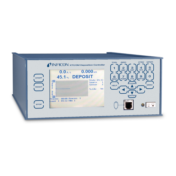
- Page 1 Cover Page XTC/3 Thin Film Deposition Controller PN 074-446-P1L...
- Page 2 All other brand and product names are trademarks or registered trademarks of their respective companies. Disclaimer The information contained in this manual is believed to be accurate and reliable. However, INFICON assumes no responsibility for its use and shall not be liable for any special, incidental, or consequential damages related to the use of this product.
- Page 3 Declaration Of Conformity Page 1...
- Page 4 Seller product was not designed nor against any defects due to plans or instructions supplied to Seller by or for Buyer. This manual is intended for private use by INFICON® Inc. and its customers. Contact INFICON before reproducing its contents.
-
Page 5: Table Of Contents
Returning Sensor to INFICON ........1-5... - Page 6 2.3.5.2 Change the IP Address in XTC/3 ....... . 2-11 2.3.5.3...
- Page 7 XTC/3 Operating Manual 3.3.2.1 Crystal Life and Starting Frequency ....... 3-8 3.3.2.2...
- Page 8 XTC/3 Operating Manual Chapter 4 XTC/3 Programming Overview ........... 4-1 Film Set Up Overview.
- Page 9 Standard Protocol..........5-6 5.2.1.1 Standard Command Packet (Host to XTC/3 Message) ....5-6 5.2.1.2 Standard Response Packet (XTC/3 to Host Message) .
- Page 10 Troubleshooting XTC/3 ........
- Page 11 XTC/3 Operating Manual 6.5.4 Specifications ..........6-30...
-
Page 12: Introduction And Specifications
This operating manual provides user information for installing, programming, and operating the XTC/3. XTC/3 is a closed loop process controller designed for use primarily in physical vapor deposition. XTC/3 monitors and/or controls the rate and thickness of thin film depositions. Deposition rate and thickness are inferred from the frequency change induced by mass added to a quartz crystal. -
Page 13: Related Manuals
When using this manual, please pay attention to the NOTES, CAUTIONS and WARNINGS found throughout. For the purposes of this manual they are defined as follows: NOTE: Pertinent information that is useful in achieving maximum XTC/3 efficiency when followed. CAUTION Failure to heed these messages could result in damage to XTC/3. -
Page 14: General Safety Information
XTC/3 Operating Manual 1.2.2 General Safety Information WARNING - Risk Of Electric Shock Do not open the XTC/3 case! There are no user-serviceable components within the XTC/3 case. Dangerous voltages may be present whenever the power cord or external input/relay connectors are present. -
Page 15: Earth Ground
XTC/3 Operating Manual 1.2.3 Earth Ground XTC/3 is connected to earth ground through a sealed three-core (three-conductor) power cable, which must be plugged into a socket outlet with a protective earth terminal. Extension cables must always have three conductors including a protective earth terminal. -
Page 16: How To Contact Inficon
Prior to being given an RMA number, a completed Declaration Of Contamination (DoC) form will be required. DoC forms must be approved by INFICON before an RMA number is issued. INFICON may require that the XTC/3 be sent to a designated decontamination facility, not to the factory. -
Page 17: Xtc/3 Specifications
XTC/3 Operating Manual 1.4 XTC/3 Specifications 1.4.1 Measurement Measurement Frequency Range . . . 6.0 to 5.0 MHz (fixed) Frequency Resolution ... ± 0.028 Hz @ 6 MHz Thickness and Rate Resolution/Measurement . -
Page 18: Process Recipe Storage
XTC/3 Operating Manual 1.4.3 Process Recipe Storage XTC/3M XTC/3S Process Programs Film Programs Process Layers process 1.4.3.1 Film Parameters Pre/Post Deposit Power Ramps....2 per film Power Level . -
Page 19: Display
XTC/3 Operating Manual Crystal Stability, Total ... . 0, 25 to 9999 Hz (1 to 24 are excluded) Crystal Quality Percent... 0 to 99% Crystal Quality Counts . -
Page 20: Source / Recorder Outputs
XTC/3 Operating Manual Power Display Range... . 0.0 to 99.9% Graphic Display Functions ..Rate Deviation at ± 5, 10, 20, or 40 Å/s or Power at 0.0 to 100%... -
Page 21: Remote Communications
XTC/3 Operating Manual # of TTL Compatible Outputs ..8 standard, Internally pulled up to 5 V (dc). May be pulled up externally to 24 V (dc) through 2.4 k resistor. minimum high level 0.5 mA load @3.75 V maximum low level 10 mA load @1.1 V... -
Page 22: Operating Environment
XTC/3 Operating Manual 1.4.10 Operating Environment Usage......Indoor only Temperature ....0 to 50°C (32-122°F) Humidity . -
Page 23: Unpacking And Inspection
XTC/3 Operating Manual 1.5 Unpacking and Inspection If XTC/3 control module has not been removed from its shipping container, do so now. Carefully examine the control module for damage that may have occurred during shipping. This is especially important if you notice obvious rough handling on the outside of the container. -
Page 24: Accessories
XTC/3 DLL ........ -
Page 25: Replacement Cables & Oscillators
Standard XTC/3 Oscillator ......PN 780-600-G1 4 m XTC/3 Oscillator ......PN 780-600-G2 1.6.4 Sensors... - Page 26 XTC/3 Operating Manual For more information about Inficon’s full line of QCM sensors, please contact your local INFICON representative or visit www.inficon.com. Table 1-1 Crystal12 sensor Crystal12 Sensor Package XL12-xxxxX XL12- Base Unit None Crystal 12 Sensor In-Vacuum Cable Assembly Length None 78 cm (30.75 in.)
-
Page 27: Initial Power On Verification
XTC/3. Never unscrew or loosen this connection. Confirm that AC line voltage is supplied and proper for XTC/3. Set the power switch on XTC/3 rear panel to On. Press the power button on the front panel. A green LED will illuminate next to the power switch. - Page 28 XTC/3 Operating Manual The LCD will display a screen similar to the one shown in Figure 1-1 Figure 1-2. Figure 1-1 XTC/3M operate screen Figure 1-2 XTC/3S operate screen 1 - 17...
-
Page 29: Installation And Interfaces
PN 779-220-G2 (20 in. BNC Cables) and Xtal 2 (CrystalTwo) Switch is required. XTC/3 uses only one Crystal Interface Unit (XIU) signal connection at XTC/3 for the dual sensor. The Xtal 2 Switch is wired in parallel with the solenoid valve (PN 750-420-G1) to route the XIU connection from one to the other crystal at the same time that the shutter is activated. -
Page 30: Sensor Installation
XTC/3 Operating Manual 2.1.2 Sensor Installation Figure 2-1 shows a typical installation of an INFICON water cooled crystal sensor in the vacuum process chamber. Use the illustration and the following guidelines to install sensors for optimum performance and convenience. Figure 2-1 Typical installation... - Page 31 Ensure there is easy access for the exchange of crystals. For systems employing two XTC/3 for simultaneous source evaporation (co-deposition), locate the sensors so the evaporant from each source is flowing to only one sensor. It is not generally possible to do this without special shielding or optional material directors.
-
Page 32: Xtc/3 Installation
XTC/3 Operating Manual 2.1.3 XTC/3 Installation XTC/3 is designed to be rack mounted with the optional rack mount kit (PN 780-702-G1). It may be also used on a table. A two-unit rack mount option kit (PN 780-702-G2) is available for mounting two XTC/3 side by side. -
Page 33: Connections To Earth Ground
XTC/3 is also connected to earth via a sealed three-core power cable, which must be plugged into a socket outlet with a protective earth terminal. Extension cables must always have three conductors including a protective earth conductor. -
Page 34: Minimizing Noise Pickup From External Cabling
Vacuum System 2.2.3 Minimizing Noise Pickup from External Cabling When a XTC/3 is fully integrated into a deposition system, there are many wire connections, each a potential path for noise to reach the inside of XTC/3. The likelihood of these wires causing a problem can be greatly diminished by adhering to the following guidelines: ... -
Page 35: Connecting The Controller
XTC/3 Operating Manual 2.3 Connecting the Controller The operation of the XTC/3 depends on the proper connection of power and signal interfaces to owner equipment and sources. 2.3.1 Verifying the Correct Input Voltage WARNING - Risk Of Electric Shock XTC/3 has line voltage present on the primary circuits whenever it is plugged into a main power source. -
Page 36: Input And Output Connections
XTC/3 Operating Manual 2.3.3.2 Input and Output Connections CAUTION The relay, relay circuit, and associated pins in the I/O connector(s) have a maximum voltage rating of 30 V (dc) or 30 V (ac) RMS or 42 V (peak). The maximum current rating per connector pin or relay contact is 2.5 Amps. -
Page 37: System I/O Connector
XTC/3 Operating Manual 2.3.3.2.1 System I/O Connector Table 2-1 System I/O connector Description Pin # XTC/3S Function Relay 1 1, 2 Source Shutter 1 Relay 2 3, 4 Source Shutter 2 Relay 3 5, 6 ** Sensor Shutter 1 Relay 4... -
Page 38: Aux I/O Connector
XTC/3 Operating Manual 2.3.3.2.2 Aux I/O Connector Table 2-3 Aux I/O connector Description Pin # XTC/3S Function Relay 7 1, 2 Thickness Setpoint Relay 8 3, 4 Soak 2 Relay 9 5, 6 Crystal Fail Relay 10 7, 8 Alarms... -
Page 39: Rs-232C Communications
(not a null modem cable) with a female 9 pin D connector on the PC end and a male 9 pin D connector at the XTC/3 end will work, however, only pins 1, 2, 3 and 5 are used. -
Page 40: Operation
CLEAR is used to erase data entry errors. If an illegal value has been entered, CLEAR will erase the error message and re-display the last valid data. MENU is used to navigate through XTC/3 displays. HELP key brings up context-related text. -
Page 41: Rear Panel Interfaces
XTC/3 Operating Manual Power This switch controls secondary power to XTC/3 between ON and STANDBY. Power is provided when the button is in its depressed position. Pilot Light A green LED, adjacent to the power switch, is illuminated when power is on. - Page 42 XTC/3 Operating Manual RS-232C Remote Communication Connector Provides a 9-pin RS-232C communications port. Ground Stud section 2.2.2, Connections to Earth Ground, on page 2-5. Recorder DAC Output Provides 0 to 10 V output selectable to correspond to Rate, Rate Deviation, and Thickness at various ranges and Power (BNC connector).
-
Page 43: Displays
XTC/3 Operating Manual 3.3 Displays Seven XTC/3 display screens are used for monitoring and programming processes: Operate Film Parameter Process List (XTC/3M only) General Parameter I/O Map Diagnostics Sensor To maximize the life of the display, it can be set to dim after a period of 1 to 99 minutes without a key press (see section 4.4.2, Hardware Parameters, on page... -
Page 44: Menu Display
(located to the right of Sensor), enter the lock code and press ENTER. The lock code message will disappear. XTC/3 will be re-locked after entering the Operate screen. 3.3.2 Operate Display The Operate screen will appear on power-up following the temporary initialization screen. - Page 45 XTC/3 Operating Manual A graphical representation of rate deviation or the power over time will also be displayed. The graph display can be modified by placing the cursor on the Y-axis graph label and pressing TOGL to toggle between rate deviation and power. The rate deviation scale can also be toggled between 5,10, 20 and 40 Å/s when the...
- Page 46 XTC/3 Operating Manual Operate Display Description (See Figure 3-4) 1. Layer Currently In Process (Film in XTC/3S) 2. Layer Time 3. Process Time (XTC/3M only) 4. % Power 5. Rate 6. Graphical Display of Rate Deviation or Power 7. Layer Thickness 8.
-
Page 47: Crystal Life And Starting Frequency
Silver crystals may also improve the deposition of oxides, but try gold crystals first. Keep in mind that silver tarnishes and cannot be kept in storage for long periods of time. INFICON silver crystals are shipped in a sealed bag filled with an inert gas to maximize shelf life. -
Page 48: Film Name Display
XTC/3 Operating Manual 3.3.3 Film Name Display Figure 3-6 Film Name display The Film Name display shows the film parameters and their values. Thirty-two films may be programmed in XTC/3M; nine in XTC/3S. Pre/Post Deposit, Deposit, Sensor, Source and Option screens are accessed from the Film Name screen. -
Page 49: Process List Display (Xtc/3M Only)
XTC/3 Operating Manual 3.3.4 Process List Display (XTC/3M only) The Process screen is present only in XTC/3M. XTC/3S is a single process, single layer controller. Figure 3-7 XTC/3M Process display A process consists of one or more layers, to be run in order. See section 4.3 on... -
Page 50: General Parameter Display
XTC/3 Operating Manual 3.3.5 General Parameter Display Figure 3-8 XTC/3M General parameter display NOTE: XTC/3S replaces Process to Run with Film To Run. XTC/3S does not support AutoStart Next Layer. The General parameter screen is subdivided into Process, Hardware and Communication Info screens. -
Page 51: I/O Map Display
4.5 on page 4-26 for XTC/3M programming details. 3.3.7 Diagnostics Display Figure 3-10 Diagnostics display The Diagnostics display is described under section 6.2, XTC/3 Diagnostics, on page 6-6. The Diagnostics display: shows firmware version shows main board serial number ... -
Page 52: Sensor Information Display
XTC/3 Operating Manual 3.3.8 Sensor Information Display Figure 3-11 Typical Sensor Information display Inactive choices will be gray. If non-zero values have been programmed for the S and/or Q parameters, the accumulated counts can be cleared on this screen. If a multi-position sensor is in use, it can be switched to the next or rotated through all its positions by positioning the cursor on Switch Crystal or Rotate Head and pressing TOGL. -
Page 53: Executing A Process
STOP freezes a process, the status information on the display is maintained and the control voltage output is set to zero. RESET, if pressed when XTC/3 is in Stop, takes a process back to the first layer. HINT: It may be desirable to execute a new process in TEST (enabled in Process sub-screen of the General Parameter display, see section 4.4.1 on page... - Page 54 XTC/3 Operating Manual 3 - 15...
- Page 55 Press START. The next layer to be run will enter pre-deposition, and continue on through deposition and post-deposition. When the layer is complete, XTC/3 will go to IDLE. If AutoStart Next Layer (XTC/3M only) has been set to Yes in the Process sub-screen of the General Parameter display, the next layer, if there is one, will be started automatically.
-
Page 56: State Descriptions
Inactive Inactive Rate is displayed and Thickness is accumulated. CRUCIBLE SWITCH XTC/3 advances to next state when the Inactive Inactive Cruc Valid input is low. If IDLE PWR of the previous layer using this source is not equal to zero, power is set to zero before the crucible position changes. - Page 57 XTC/3 Operating Manual Table 3-1 State descriptions (continued) STATE CONDITION RELAY CONTACT STATUS Source Sensor Shutter Shutter NOTE: The following are Deposit states. CONTROL DELAY Constant Power at Soak Power 2. Begins Active Active rate control when the control delay time (Deposit state) elapses.
- Page 58 XTC/3 Operating Manual Table 3-2 Output states Output Active Inactive Source Shut 1 In any deposit state When leaving control states Source Shut 2 Sensor Shut 1 In shutter delay or any deposit Closes when leaving control states. state. In RateWatcher Hold...
- Page 59 When Start or Reset is done. seconds of a crucible switch (M only) If Stop on Alarms is set to No, XTC/3 will give the error message but will not do anything else, it stays in Crucible Switch. If the Crucible Valid...
- Page 60 XTC/3 Operating Manual Table 3-2 Output states (continued) Output Active Inactive Shutter Delay Fail Shutter delay is enabled and the When Start or Reset is done rate deviation is greater than 5% (M only) If Stop on alarms is set to No, the unit or 0.5 Å...
- Page 61 READY or IDLE state and a START command is executed while NON-DEP HOLD is active, XTC/3 will progress to the first pre-deposit state with a non zero state time. If XTC/3 is in the Crucible Switch state, waiting for the Cruc Valid input, and NON-DEP HOLD is activated when the Cruc Valid input is activated, XTC/3 will progress to the next pre-deposit state having a non zero state time.
-
Page 62: Alarms And Stops
Source sub-screen of the Film Parameter display, for five continuous seconds. 3.5.1.2 Stops The following actions or conditions produce a STOP state. This condition is indicated by the STOP message on XTC/3 and the closure of the STOP relay (if assigned): ... -
Page 63: Recovering From Stop
XTC/3 Operating Manual A CRYSTAL FAIL detected during the DEPOSIT state if the Time Power parameter (Option sub-screen of the Film Parameter display ) is set to No (when crystal switching is not available). Following the POST-DEPOSIT states of a layer when the DEPOSIT state completes in TIME POWER. -
Page 64: Ion Assisted Deposition
Rate control must be maintained at ± 5% Å/sec or ± 0.5 Å/sec, whichever is greater, of the desired deposition rate for five seconds before XTC/3 will enter the DEPOSIT state, opening the source shutter and thus exposing the substrate to a well controlled rate of evaporant flux. -
Page 65: Crucible Switching
4.5.3 on page 4-29.) 3.6.8 Crystal Switching XTC/3 offers a choice of Single, CrystalTwo, CrystalSix, Crystal12, Rotary or Dual Head sensors. The CrystalTwo, CrystalSix, Crystal12, Rotary and Dual Head sensors provide one or more backup crystals in case a crystal fails during deposition. -
Page 66: Crystaltwo
A crystal (sensor in the case of Dual Head) switch will automatically occur when: XTC/3 is configured for a CrystalTwo or Dual Head sensor type, a film is STARTed or running and there is another good crystal available when the active crystal fails. -
Page 67: Crystalsix
Clear Failed Crystals or by powering down and up again. In both cases, XTC/3 will run the next layer using the last crystal position it switched to. Crystal Fail can also be cleared by executing a crystal switch from the front... -
Page 68: Rotary Sensor Crystal Switching
(i.e., one pulse to move one position); there is no intermediate position. XTC/3 will not keep track of which position the Rotary Sensor is on nor will it keep track of which crystals are good and which are failed. All crystals are assumed to be good following a START command. -
Page 69: Xtc/3S Sensor Shutter / Crystalswitch Output
If Start Without Backup is set to Yes, a layer with a multi-position sensor can be started even if there is only one good crystal. Additionally, if Start Without Backup is set to Yes and XTC/3 switches to the backup crystal during the process, it will continue using the backup crystal until the process is RESET, even if the primary crystal is replaced. -
Page 70: Ratewatcher
STOP. The handheld controller is connected to XTC/3 with a coiled cord and attaches with a modular plug to the front panel of XTC/3. The POWER/STOP switch located at the top of the controller is asymmetrical to increase awareness of the direction of power increment and decrement. -
Page 71: Lock Code
POWER/STOP switch laterally. A STOP is produced by pressing POWER/STOP. A crystal switch is activated by pressing the red button on the body of the XTC/3. This action alternates the active crystal of a dual head configuration or advances the multi-position sensor to the next available crystal. -
Page 72: Tcp/Ip
5.3.5.5 on page 5-42. 3.6.15 TCP/IP The optional TCP/IP interface will provide all the commands available through the standard RS232 interface. The interface uses a static address entered via XTC/3 front panel (see section 4.4.3.1 on page 4-25). DHCP is not supported. -
Page 73: Xtc/3 Programming
XTC/3 Programming 4.1 Overview The following basic procedure is used to program XTC/3. If a lock code has been programmed, it must be entered after cursoring to the Lock Code on the Menu screen. (All steps do not necessarily have to be followed in the given order.) Make sure XTC/3 is in READY. - Page 74 XTC/3 Operating Manual Configure General Parameters From the General Parameter display, three sub-screens can be accessed: Process; Hardware; and Comm Info. The Process screen provides for a number of selections including which process (XTC/3M) or film (XTC/3S) to run. The Hardware screen allows selecting the sensor type, source control voltage range and polarity, chart recorder mode, audio feedback and LCD dimmer time.
-
Page 75: Film Set Up Overview
XTC/3 Operating Manual 4.2 Film Set Up Overview 4.2.1 Film Set Up The film screen appears after pressing the MENU key, then cursoring down to Film Parameter and pressing Menu. Figure 4-1 Main Menu screen XTC/3M Figure 4-2 Pre/Post Film Programming Screen From the Film Parameter display, Pre/Post, Deposit, Sensor, Source and ◄►... -
Page 76: Film Definition
XTC/3 Operating Manual 4.2.2 Film Definition A film is defined by the parameters needed to run it, including sensor and source numbers, source heat-up and cool down parameters, deposition rate and final thickness, material parameters, control loop parameters, etc. XTC/3M can define 32 films which can be named. -
Page 77: Film Definition Parameters
SOAK POWER 2 ....0.0 to 100% This parameter is usually set to the power level at which the source material evaporates material at about the target rate. XTC/3 ramps the power level from SOAK POWER 1 to SOAK POWER 2 linearly over the time period RISE TIME 2. - Page 78 Deposit state to the Idle Power level. The control voltage is maintained at the Idle Power level until XTC/3 enters STOP or until the next layer, using the specified source, is started, or the turret source is rotated.
-
Page 79: Deposit
XTC/3 Operating Manual 4.2.3.2 Deposit Figure 4-3 Deposit Film Programming screen FILM NUMBER ....1 to 32 (XTC/3M) 1 to 9 (XTC/3S) RATE ......0.0 to 999.9 Å/s This specifies the rate at which the deposition is to be controlled during the DEPOSIT and Shutter Delay states. -
Page 80: Sensor Parameters
XTC/3 Operating Manual RW ACCURACY ....1 to 99% During the rate sampling period, the deposition rate is measured by the crystal and source power control is active. When the measured rate is within the desired accuracy continuously for five seconds, the shutter is closed and the deposition state returns to HOLD. -
Page 81: Setting S&Q Parameters (Soft Crystal Failures)
By programming non-zero values for Stability and/or Quality, various improvements in process control can be achieved if one or more backup crystals are available. XTC/3 can be made to automatically switch to a different crystal and continue the deposition normally, or complete the run in the TIME-POWER mode or even terminate the process if a backup crystal is not available. -
Page 82: Quality
If the rate deviation is less than the programmed threshold, the COUNTS value is decremented. COUNTS is not allowed to have negative values. If COUNTS exceeds the value programmed, XTC/3 will automatically crystal switch, complete the process on TIME-POWER or STOP the process. The rate deviation is computed on each individual rate measurement during the deposit phase, i.e., every 250 ms. -
Page 83: Source Parameters
XTC/3 Operating Manual 4.2.3.4 Source Parameters Figure 4-5 Source Film Programming screen SOURCE ... . 1, 2 This parameter determines which source output is to be used for source control voltage for the material being defined. - Page 84 XTC/3 Operating Manual CONTROL GAIN ..0.01 to 100.0 Å/sec/% Pwr This parameter determines the change in % Power for a given rate deviation (dRate/dPower). The larger the process gain value, the smaller the change in power for a given rate error.
- Page 85 XTC/3 Operating Manual DEAD TIME ..0.1 to 100.0 sec This value is defined as the time difference between a change in % power and the start of an actual change in rate. The default value is 1.
-
Page 86: Option
TIME POWER ..Yes / No using TOGL key. Default is No. The Time-Power state will only be entered while XTC/3 is in the DEPOSIT or RATE RAMP state and the film program has been set to complete on Time-Power in the event of a failed crystal when there is no backup crystal. - Page 87 Delay. After the Control Delay Time elapses, control loop action is initiated. Both ..XTC/3 will first enter a Shutter Delay state followed by Control Delay. TRANSFER SENSOR ... Yes / No Press the TOGL key to move through the choices.
-
Page 88: Process Set-Up Overview (Xtc/3M Only)
XTC/3 Operating Manual 4.3 Process Set-Up Overview (XTC/3M only) Figure 4-10 Main Menu screen In XTC/3M, the Process display appears after pressing the MENU key, then cursoring down to Process List and pressing Menu. XTC/3S does not have the Process List menu option. -
Page 89: Process Definition
XTC/3 Operating Manual 4.3.1 Process Definition Figure 4-11 Process screen 4.3.1.1 Process Number PROCESS ... 1 to 99 Upon entering the Process screen, the process displayed will be the one displayed when this screen was last left. -
Page 90: General Parameters
XTC/3 Operating Manual Entering a film number between 1 and 32 next to a layer number, followed by the ENTER key, will place the desired film in that layer. If a film number was previously entered, it will be replaced. Entering a 0 will delete the specified film and shift all following films up. -
Page 91: Process Parameters
XTC/3 Operating Manual 4.4.1 Process Parameters Figure 4-13 XTC/3M Process screen Figure 4-14 XTC/3S Process screen PROCESS TO RUN ..1 to 99 (XTC/3M only) Selects the process to be run. Only processes with layers may be entered. - Page 92 STOP ON MAX POWER . . . Yes / No Press the TOGL key to move through the choices. Default setting is No. If set to Yes, XTC/3 will stop if Max Power condition has been true for 5 seconds continuously.
-
Page 93: Hardware Parameters
XTC/3 Operating Manual LOCK CODE ..1 to 9999 The L Lock lock code is set by moving to the Lock Code XXXX and entering the desired code of up to 4 digits. If no lock code is desired, no entry needs to be made. - Page 94 XTC/3 Operating Manual RECORDER MODE ..Rate, Thickness, Power, Rate Deviation. Press the TOGL key to move through the choices. Default is Rate. RANGE ..100, 1000 Press the TOGL key to move through the choices. Default is 1000.
-
Page 95: Xtc/3S Film Select Option
XTC/3 Operating Manual 4.4.2.1 XTC/3S Film Select Option Figure 4-16 XTC/3S Film Select INPUT OPTION ....Standard, Film Select (XTC/3S only) Press the TOGL key to move through the choices. Default is Standard. Selecting the Film Select option allows selecting one of the 9 films based on the state of the Film Select inputs 5, 6, 7 and 8 as shown in the table below. -
Page 96: Comm Info
XTC/3 Operating Manual 4.4.3 Comm Info Figure 4-17 Comm Info Screen with TCP/IP Option installed NOTE: IP address and net mask are initialized 1 minute after power-up. IP address and net mask text are grayed if no TCP/IP option is installed or if communication cannot be established. -
Page 97: Remote Communication Parameters
The optional TCP/IP interface supports static addresses; DHCP is not supported. NOTE: IP address and net mask are initialized 1 minute after power-up. After this time, they may be changed and XTC/3 must be power-cycled for the new values to become active. -
Page 98: I/O Overview
XTC/3 Operating Manual 4.5 I/O Overview Figure 4-18 XTC3/M Main Menu screen The I/O Map display appears after pressing the MENU key, then cursoring down to I/O Map and pressing MENU. Figure 4-19 XTC/3M All I/O screen The All I/O screen displays the complete digital I/O map. The functions of inputs 1 to 9 are shown in the upper portion of the screen and the status of the outputs is shown on the lower portion of the screen. -
Page 99: Xtc/3S Inputs And Outputs
XTC/3 Operating Manual 4.5.1 XTC/3S Inputs and Outputs In XTC/3S, the fixed I/O will be displayed on the I/O Map screen. The assignment of the 9 fixed inputs corresponds to the default assignments in XTC/2. Also, refer to section 4.4.2.1, XTC/3S Film Select Option, on page 4-23 for inputs. -
Page 100: Xtc/3M Inputs
XTC/3 Operating Manual 4.5.2 XTC/3M Inputs Figure 4-22 Inputs screen 1 (XTC/3M only) Figure 4-23 Inputs screen 2 (XTC/3M only) In XTC/3M, this screen allows modification of the 9 inputs. On the right side of the parameter panel will be a column of the inputs as they are currently programmed. -
Page 101: Xtc/3M Outputs
XTC/3 Operating Manual 4.5.3 XTC/3M Outputs The Relay Outputs and TTL Outputs screens allow modification of the 12 relays or the 8 TTL outputs, respectively. All relays (1 to 12) and TTL Open Collector outputs (13 to 20) are selectable to perform the functions shown on the screen. Any number of outputs may be assigned to the same function. - Page 102 XTC/3 Operating Manual Figure 4-25 Relay Outputs 2 Figure 4-26 Relay Outputs 3 Figure 4-27 Relay Outputs 4 4 - 30...
-
Page 103: Clear Input Or Output
XTC/3 Operating Manual Figure 4-28 TTL Outputs NOTE: Three additional selection screens, identical to those for the Relay outputs, are available for selecting additional TTL Outputs. NOTE: Three consecutive relay or TTL outputs must be available when selecting the BCD output function, Cruc Src 1 BCD or Cruc Src 2 BCD. -
Page 104: Remote Communications
XTC/3 may be remotely controlled, programmed or interrogated. This is accomplished through remote communications and the use of a remote command set. XTC/3 will respond to messages that contain these commands. It will accept and operate on messages one at a time. It will respond to each command by carrying out valid operations and/or returning a message to the sender. -
Page 105: Physical Connections
5.1.3 RS-232C Serial Port RS-232C serial communications are accomplished through an industry standard 9-pin female connector found on the rear panel of XTC/3. A mating male connector is required for attachment of a host interface. The host and XTC/3 can be separated by up to fifty feet using multiconductor shielded data cable. -
Page 106: How To Set Up The Network Protocol On The Pc
Most personal computers are configured to obtain the IP address, an address which defines the computer on the Internet, automatically from a server. To communicate directly with XTC/3, the Internet protocol (IP) on the PC must be configured manually and an ethernet crossover cable (PN 600-1211-P5) must be connected between the PC and XTC/3. - Page 107 XTC/3 Operating Manual Figure 5-2 Local Area Connection Properties On the General tab, select Internet Protocol (TCP/IP) and press the Properties button, as shown in Figure 5-3. Figure 5-3 Internet Protocol (TCP/IP) Properties 5 - 4...
- Page 108 IP address to use when communicating with XTC/3. XTC/3 is shipped from INFICON with a pre-assigned address of 10.211.70.203. To communicate directly with XTC/3 from a PC, the PC must also be assigned an address that starts with 10.211.70 but cannot be set to 10.211.70.203.
-
Page 109: Standard Protocol Message Format
I......Or x...x..... . . One or more of x included 5.2.1.1 Standard Command Packet (Host to XTC/3 Message) <length><message><checksum>... - Page 110 XTC/3 Operating Manual Command Sub-group = 1 ASCII byte, used with some command groups to further specify commands. For command Q and U: F – Film G - General I - Input N - Film Name O - Output P - Process T - Output Type No sub-groups are allowed for H, E, S or R.
-
Page 111: Standard Response Packet (Xtc/3 To Host Message)
XTC/3 Operating Manual 5.2.1.2 Standard Response Packet (XTC/3 to Host Message) <Length><CCB><Timer><Response Message><Checksum> Length ..... . . 2 bytes Low / High (not including checksum or length bytes). - Page 112 C = Illegal ID D = Illegal format E = Data not available F = Cannot do now (some commands require XTC/3 to be in Ready/Stop). L = Length Error, must be greater than 0 and equal to or less than 57,800.
-
Page 113: Standard Communication Commands
XTC/3 Operating Manual 5.2.2 Standard Communication Commands NOTE: The following only include the “command” portion of the command packet and the “response” portion of the response packet. The headers/trailers are assumed. (See Protocol documentation above for their definition.) General definitions <Float>... -
Page 114: Standard Query Commands
XTC/3 Operating Manual 5.2.2.3 Standard QUERY Commands 5.2.2.3.1 Query Block Command: QB<Command ID> Command ID = See listing below Response: Depends on Command ID. See listing that follows Command ID = 1 ”All Parameters” The command will return all parameters in the following order. Formats are listed in the individual commands. - Page 115 XTC/3 Operating Manual Response: <Number of Bytes in Response><General Parameters><Film 1 Parameters>…<Film32 Parameters><Inputs><Outputs><Output Types><Film 1 Name>…<Film 32 Name> Number of Bytes in Response (2 bytes) All General parameters (4 bytes per parameter) All parameters for each film (4 bytes per parameter) (9 or 32 films based on...
-
Page 116: Standard Query Film Name (Xtc3/M Only)
XTC/3 Operating Manual 5.2.2.3.2 Standard Query Film Name (XTC3/M only) Command: QN <Film Number> Film Number = <Byte> 1-32 Response: <String> (maximum 15 characters, plus terminating null character) String = Null terminated series of ASCII characters 5.2.2.3.3 Standard Query Film Parameters Command: QF <Command ID>... -
Page 117: Standard Query Input Definition (Xtc/3M Only)
XTC/3 Operating Manual 5.2.2.3.5 Standard Query Input Definition (XTC/3M Only) Command: QI <Input Number> Input Number = <Byte> 1-9, 255 (255=All 9 inputs) Response: If Input Number was 1 – 9: <Input Definition> If Input Number was 255: <Input 1 Definition> <Input 2 Definition> … <Input 9 Definition>... -
Page 118: Standard Query Output Definition (Xtc/3M Only)
XTC/3 Operating Manual 22 (Select Process 1-64, 6 bits, bit 5) 23 (Select Process 1-64, 6 bits, bit 6) 24 Select Process 1-99, 7 bits* 25 (Select Process 1-99, 7 bits, bit 2) 26 (Select Process 1-99, 7 bits, bit 3) - Page 119 XTC/3 Operating Manual 2 Source Shutter 2 3 Sensor Shutter 1 4 Sensor Shutter 2 5 Stop 6 End of Process 7 Thickness Setpoint 8 Crystal Fail 9 Alarms 10 Source in use (Open=1; closed=2) 11 Final Thickness 12 End of Film...
- Page 120 XTC/3 Operating Manual 33 Crystal Switching 34 Crucible Switcher Fail 35 Shutter Delay Error 36 Computer Control 37 Crucible Select Source 1 Binary (8 outputs required, one/position)* 38 (Crucible Select Source 1 Binary, bit 2) 39 (Crucible Select Source 1 Binary, bit 3)
-
Page 121: Standard Query Output Type Definition (Xtc/3M Only)
XTC/3 Operating Manual 5.2.2.3.7 Standard Query Output Type Definition (XTC/3M Only) Command: QT <Output Number> Output Number = <Byte> 1-20, 255 (255=all outputs) Response: If Output Number was 1 – 20: <Output type> If Output Number was 255: < Output 1 type > < Output 2 type > … < Output 20 type >... -
Page 122: Standard Update Commands
XTC/3 Operating Manual Command ID = 3 "Specific Layer" <Parameter> = <2 Bytes>Desired Layer Response: <Byte> 1-32, film number of given layer 5.2.2.4 Standard UPDATE Commands 5.2.2.4.1 Update Block Command: UB< Command ID> <List of parameters> Response: None (Just header and trailer) List of parameters for Command ID 1 = <Number of Bytes in Response><General Parameters><Film 1... -
Page 123: Standard Update Film Name (Xtc/3M Only)
XTC/3 Operating Manual All General parameters (4 bytes per parameter) All parameters for each film (4 bytes per parameter) (9 or 32 films based on XTC/3S or XTC/3M) All input definitions (9) (1 byte per input) (XTC/3M only) All output definitions (20) (1 byte per output) (XTC/3M only) -
Page 124: Standard Update Film Parameters
XTC/3 Operating Manual 5.2.2.4.3 Standard Update Film Parameters Command: UF <Command ID> <Film Number> <Parameter Value> Command ID = <Byte>. See “UF Command ID” column of Table 5-2. Film Number = <Byte> 1-9 (XTC/3S ) or 1-32 (XTC/3M) Parameter Value = <Integer> | <Float>... - Page 125 XTC/3 Operating Manual Table 5-2 Standard film parameters Name Units / Allowed Values Data Type High Limit / Notes / Format Limit (0x5546) Command ID Rise Time 1 MM:SS 99:59 (0x00) (Seconds) (5999) Soak Power 1 Float 100.0 (0x01) xxx.x...
- Page 126 XTC/3 Operating Manual Table 5-2 Standard film parameters (continued) Name Units / Allowed Values Data Type High Limit / Notes / Format Limit (0x5546) Command ID RW Hold Time MM:SS 99:59 (0x0e) (Seconds) (5999) Sensor Cannot change if film is running...
- Page 127 XTC/3 Operating Manual Table 5-2 Standard film parameters (continued) Name Units / Allowed Values Data Type High Limit / Notes / Format Limit (0x5546) Command ID Z-Ratio Float 0.100 9.999 (0x1d) x.xxx xx.xx xxx.x Time Power 1=Yes, (0x1e) 0 = No...
-
Page 128: Standard Update General Parameters
XTC/3 Operating Manual 5.2.2.4.4 Standard Update General Parameters Command: UG <Command ID> <Parameter Value> Command ID = <Byte> See “UG Command ID” column of Table 5-3. Parameter Value = <Integer> | <Float> Integer = 4 byte, low to high Float = 4 byte, ANSII standard, single precision, low to high Description: Type of parameter value depends on command ID, see “DataType”... - Page 129 XTC/3 Operating Manual Table 5-3 Standard general parameters (continued) Name Units / Allowed Data High Values / Notes Type / Limit Limit (0x5547) Format Command ID Sensor 2 Type 0 = Single (0x07) 1 = CrystalTwo (5 for Query 2 = CrystalSix...
-
Page 130: Standard Update Input Definition (Xtc/3M Only)
XTC/3 Operating Manual Table 5-3 Standard general parameters (continued) Name Units / Allowed Data High Values / Notes Type / Limit Limit (0x5547) Format Command ID Auto Start Next Layer 1 = Yes, 0 = No (XTC/3M only) 16 (0x10) -
Page 131: Standard Update Process Parameters (Xtc/3M Only)
0 to 256 (0x00 to 0xFF) at a rate of 4x per second. XTC/3 stores the S0 data set valid for each timer tick and returns that specific data set when the S0 command is sent with that particular timer tick. If the timer tick sent... - Page 132 XTC/3 Operating Manual seconds (256 timer ticks / 4 per second). Therefore, to get current data, the timer tick must first be extracted from a prior command and then incremented every 250 msec and inserted in the S0 as the <Action Value>.
- Page 133 XTC/3 Operating Manual Table 5-4 Standard Status commands (continued) Description Response: (0x53) Description (Data Format) Units -Detail- Command ID 1 (0x01) * Current Rate (Float) Å/Sec -One second rolling average- 2 (0x02) Current Power (Float) % 3 (0x03) Current Thickness (Float) kÅ...
- Page 134 XTC/3 Operating Manual Table 5-4 Standard Status commands (continued) Description Response: (0x53) Description (Data Format) Units -Detail- Command ID Input Status Byte (2 Byte) - Each bit represents an input - (0 = not set, 1 = set) (0x0c) Input 1 = LSB, Input 9 = 9th bit...
- Page 135 XTC/3 Operating Manual Table 5-4 Standard Status commands (continued) Description Response: (0x53) Description (Data Format) Units -Detail- Command ID Data Log Returns data as follows Layer # (Int) (0x13) Film # (Int) Rate (Float) Å/Sec - One second average- Thickness (Float) kÅ...
- Page 136 XTC/3 Operating Manual Table 5-4 Standard Status commands (continued) Description Response: (0x53) Description (Data Format) Units -Detail- Command ID Status Messages (4 bytes) Each bit indicates which status message is displayed. (0x21) 0x80000000 = Max Power 0x40000000 = Crystal Fail...
-
Page 137: Standard Remote Commands
Stop Stops the layer, puts power to zero, closes shutters, etc. (0x01) Reset If in Stop, resets XTC/3 to the Ready state, at the beginning of the process. (0x02) Remote lock on Prevents the update of parameters via the front panel. - Page 138 (0x0f) and their normal functions are overridden. XTC/3 must be in this mode to remotely set or clear relays (R17 and R18). If the unit is an XTC/3M an Illegal ID error is returned. Exit comm. I/O mode Exits the Communication I/O mode, returns Used in XTC/3S only.
-
Page 139: Xtc/2 Protocols
XTC/C Ck Sum or XTC/C No Ck Sum has been selected under the RS-232 Protocol parameter. TCP/IP always uses the Standard protocol. Unlike XTC/3’s standard protocol, which is binary based, XTC/2 protocols are ASCII based. That is, numbers are represented by their ASCII codes, not as "floats"... -
Page 140: Xtc/2 Serial Communication With Checksum
XTC/3 Operating Manual 5.3.2 XTC/2 Serial Communication with Checksum This portion of the protocol is in effect in addition to the portion described under section 5.3.1 above if XTC/2 Ck Sum or XTC/C Ck Sum has been selected under the RS-232 Protocol parameter. -
Page 141: Xtc/2 Error Codes
XTC/3 Operating Manual 5.3.4 XTC/2 Error Codes Table 5-6 XTC/2 error codes Code Description Illegal command Illegal Value Illegal ID Illegal command format No data to retrieve Cannot change value now Bad checksum 5 - 38... -
Page 142: Xtc/2 Message Strings
C, depending on the RS232 protocol set, and x.xx is the software revision code. The format is: H 5.3.5.3 XTC/2 QUERY Command The Query command returns information concerning current XTC/3 parameter values. The format of the query command is: Q pp F - Query parameter pp of film F or Q pp L for layer parameters. A space is... - Page 143 XTC/3 Operating Manual Table 5-7 XTC/2 parameter definition table (for QUERY and UPDATE commands) XTC/2 XTC/3 Parameter Range Xtal Switch Q 0 - 9 (See XTC/2 manual section 4.6) Tool Factor 1 10 - 500.0 Tool Factor 2 10 - 500.0 Deposition Rate 0 - 999.9...
-
Page 144: Xtc/2 Update Command
XTC/3 Operating Manual Table 5-8 Q40 command responses Command XTC/3S Response XTC/3M Response Q40 0 "a 0 0 " (a = 1 to 9, "a b c" (a = 1 to 32, b = 0 to 32, 0 = no film in layer) -
Page 145: Xtc/2 Status Command
XTC/3 Operating Manual NOTE: In XTC/2 one can program a zero film number in layer two and a good film number in layer three. This is not allowed in XTC3. If a zero is programmed in layer two and there is a good film number in layer three the film in layer three is then placed in layer two. - Page 146 XTC/3 Operating Manual S6..Active layer. x S7..Active film x S8..Active sensor. x S9..Crystal life (%). x % to xx % S10.
- Page 147 XTC/3 Operating Manual S12 ..Input status - returns 9 ASCII bytes in order byte 1 to 9, 1 byte per input. Each byte has an ASCII value of 0 or 1, corresponding to the input’s status.
- Page 148 XTC/3 Operating Manual 1 = Selection active, 0 = default state for selection Also see S22 below. NOTE: In the default configuration, bits 8 and 9 will return values of 1 whereas the defaults for these bits was 0 in XTC/2. If it is desired to make the S20...
-
Page 149: Xtc/2 Remote Commands
9 Error 9 10 No Errors S22 ..XTC/3 configuration readout, same as S20. S30 ..Returns status of each crystal of a multi-head sensor. S31 ..Returns a rolling 6.25 second average (updated every 0.25 seconds) of the measurement rate. - Page 150 XTC/3 Operating Manual R12..Zero thickness. Simulates remote input or front panel ZERO keystroke. R13..Final thickness-end deposit trigger. Simulates remote input. R14..CrystalSwitch. Equivalent to front panel XTSW keystroke.
-
Page 151: Xtc/2 Sample Host Programs
5.3.5.7.1 XTC/2 Program Without Checksum 10 ’----XTC/3 RS232 COMMUNICATIONS PROGRAM WITHOUT CHECKSUM---- 20 ’ 30 ’------THIS PROGRAM IS DESIGNED TO TRANSMIT INDIVIDUAL COMMANDS TO XTC/3 AND ACCEPT THE APPROPRIATE RESPONSE FROM XTC/3, WRITTEN IN GWBASIC 2.32. 40 ’ 50 OPEN "COM1:9600,N,8,1,CS,DS" AS #1 :’--OPEN COMM PORT 1 60 NAK$ = CHR$(21): ACK$ = CHR$(6) :’--DEFINE ASCII CODES... -
Page 152: Xtc/2 Program With Checksum
10 ’--XTC/3 RS232 COMMUNICATIONS PROGRAM WITH CHECKSUM USING THE INFICON FORMAT-- 20 ’ 30 ’------THIS PROGRAM IS DESIGNED TO TRANSMIT INDIVIDUAL COMMANDS TO XTC/3 AND ACCEPT THE APPROPRIATE RESPONSE FROM XTC/3, WRITTEN IN GWBASIC 2.32. 40 ’ 50 OPEN "COM1:9600,N,8,1,cs,ds" AS #1 :’--OPEN COMM PORT 1 60 STX$ = CHR$(2) : NAK$ = CHR$(21) : ACK$ = CHR$(6) :’--DEFINE ASCII CODES... - Page 153 290 PRINT #1, STX$ + SIZEM$ + SIZEL$ + CMD$ + CHECKSUM$ 300 ’ 310 ’----RECEIVE RESPONSE MESSAGE FROM XTC/3---- 320 TOUT = 3: GOSUB 510 :’--SET TIMER AND WAIT FOR 330 IF I$ <> STX$ THEN 290 :’ START OF TRANSMISSION CHARACTER.
-
Page 154: Troubleshooting, Status And Error Messages
Crystal switching is in progress. CRYSTAL SW FAIL Crystal switching failed to complete. DELAY FAILURE Indicates that XTC/3 was unable to achieve rate control during the Shutter Delay state. DELAYED START Start will be executed after XTC/3 completes internal processing. - Page 155 Ethernet values cannot be changed at this time. ETHERNET VALUES HAVE CHANGED Changes take effect on power up. FRONT PANEL Indicates that XTC/3 was stopped by pressing STOP on the front panel. HANDCONTROL Indicates that XTC/3 was stopped by pressing STOP on the Handheld Controller.
- Page 156 Message appears if trying to enter the Diagnostics mode while a process is running. PROCESS VAR DEFAULT Indicates XTC/3 process variables have been set to their default values. Any previous process variables will have been changed to the default values. 6 - 3...
- Page 157 XTC/3 Operating Manual R LOCK Indicates XTC/3 is in a Remote Program Lock mode. This prohibits any parameter from being entered from the front panel until the lock is released via remote communications. RATE DEV ERR Indicates XTC/3 entered the Stop mode because rate control was not achieved within 60 seconds.
- Page 158 TESTING XIU XIU test in progress. TIME POWER Indicates XTC/3 entered the Time Power mode due to a crystal failure of the last good crystal and Time Power was set to Yes. TRANSFER DELAY Indicates XTC/3 is in the transition from the pre-deposit sensor to the deposit sensor.
-
Page 159: Xtc/3 Diagnostics
XTC/3 Operating Manual 6.2 XTC/3 Diagnostics The initial page shows the revision level of the firmware as well as serial numbers. Figure 6-1 Diagnostics display Pressing Enter permits various test and maintenance functions. Figure 6-2 Diagnostics Test/Maintenance display 6 - 6... - Page 160 COMM PORT is okay; or the test failed and the COMM PORT is bad. NOTE: The RS-232C Loop Back connector, PN 760-406-P1 must be installed on XTC/3 RS-232C port for the self-test to work properly. 6 - 7...
-
Page 161: Troubleshooting Guide
XTC/3 Operating Manual 6.3 Troubleshooting Guide If XTC/3 fails to work, or appears to have diminished performance, the following Symptom/Cause/Remedy chart may be helpful. CAUTION There are no user serviceable components within the XTC/3 case. WARNING - Risk Of Electric Shock Potentially lethal voltages are present when the line cord, Inputs or Outputs are connected. -
Page 162: Troubleshooting Xtc/3
XTC/3 c. incorrect line voltage c. have qualified personnel verify line voltage 2. XTC/3 "locks" up a. cover or back panels not a. - Page 163 "beating" with is not a multiple of XTC/3 XTC/3 measurement measurement frequency (4 Hz) frequency 9. power-on LED a. internal hardware defect a. contact INFICON...
- Page 164 XTC/3 Operating Manual Table 6-1 Troubleshooting XTC/3 (continued) SYMPTOM CAUSE REMEDY 10. crystal fail message a. XIU/oscillator not a. verify proper sensor/oscillator is always on connected connections b. XIU oscillator b. if available, insert a known malfunctioning working XIU/oscillator in place of suspect one;...
-
Page 165: Troubleshooting Transducers/Sensors
6.5 on page 6-25 for a discussion of its use and diagnostic capabilities. 6.3.2.1 Verifying Crystal Switching and Rotation The Sensor Information screen allows checking active sensor function from XTC/3 front panel. Refer to section 3.3.8, Sensor Information Display, on page 3-13. - Page 166 XTC/3 Operating Manual Table 6-2 Troubleshooting transducers/sensors SYMPTOM CAUSE REMEDY 1. large jumps of thickness a. mode hopping due to a. replace crystal reading during deposition defective crystal b. stress causes film to peel b. replace crystal from crystal surface c.
- Page 167 RF interference from c. verify earth ground, use sputtering power supply ground strap adequate for RF ground, change location of XTC/3 and oscillator cabling away from RF power lines, connect XTC/3 to a different power line d. cables/oscillator not d.
- Page 168 XTC/3 Operating Manual Table 6-2 Troubleshooting transducers/sensors (continued) SYMPTOM CAUSE REMEDY 5. thermal instability: large a. inadequate cooling a. check cooling water flow changes in thickness water/cooling water rate, be certain that cooling reading during source temperature too high water temperature is less warm-up (usually causes than 30°C;...
- Page 169 XTC/3 Operating Manual Table 6-2 Troubleshooting transducers/sensors (continued) SYMPTOM CAUSE REMEDY 6. poor thickness a. variable source flux a. move sensor to a more reproducibility distribution central location to reliably sample evaporant, ensure constant relative pool height of melt, avoid tunneling into the melt b.
- Page 170 XTC/3 Operating Manual Table 6-2 Troubleshooting transducers/sensors (continued) SYMPTOM CAUSE REMEDY 8. CrystalSix and Crystal12: a. loss of pneumatic supply, a. ensure air supply is crystal switch problem or pressure is insufficient regulated at 80-90 PSIG (does not advance or not...
-
Page 171: Troubleshooting Computer Communications
Diagnostics: Blinking 1-1-1 - starting the operating (Bottom left) system; Blinking 1-5-1 - configuration has been returned to factory default; contact INFICON Service if other blinking patterns occur; On - normal operation Yellow Blinking - network data is transmitted or received... -
Page 172: Replacing The Crystal
XTC/3 Operating Manual 6.4 Replacing the Crystal The procedure for replacing the crystal is basically the same with all transducers, except the Cool Drawer, RSH-600, CrystalSix and Crystal12. CAUTION Always use clean nylon lab gloves and plastic tweezers for handling the crystal (to avoid contamination which may lead to poor adhesion of the film to the electrode). -
Page 173: Shuttered Front Load Single And Front Load Dual Sensors
XTC/3 Operating Manual Figure 6-3 Front load single sensor (exploded) Standard Crystal Holder (PN 750-172-G1) Crystal (PN 008-010-G10) Fully Coated Face (Gold) Crystal Retainer (PN 007-023) Finger Spring Contact (PN 750-171-P1) Standard Crystal Sensor Body (PN 750-207-G1) In-Vacuum Cable to XIU Water Tubes 6.4.2 Shuttered Front Load Single and Front Load Dual Sensors... - Page 174 XTC/3 Operating Manual Hold the drawer by the handle and turn it upside down to remove the spent crystal. Install a new crystal in the drawer. Observe its orientation. The pattern electrode should face upward as shown in Figure 6-5.
-
Page 175: Bakeable Sensor
XTC/3 Operating Manual 6.4.4 Bakeable Sensor For the Bakeable sensor, the procedure is the same as the Front Load Single sensor except that the cam assembly must be unlocked by flipping it up. Once the crystal has been replaced, place a flat edge of the holder flush with the cam mechanism and lock it in place with the cam. -
Page 176: Sputtering Sensor
XTC/3 Operating Manual 6.4.5 Sputtering Sensor Observe the general precautions for replacing crystals and follow the instructions below to replace the crystal in a sputtering sensor. Grip the body assembly with your fingers and pull it straight out to separate it from the water-cooled front part. -
Page 177: Crystal Snatcher
XTC/3 Operating Manual 6.4.6 Crystal Snatcher Use the crystal snatcher, supplied with the sensor (excluding Cool Drawer sensors), as follows: Insert crystal snatcher into ceramic retainer (1) and apply a small amount of pressure. This locks the retainer to the snatcher and allows the retainer to be pulled straight out (2). -
Page 178: Crystal Sensor Emulator Pn 760-601-G2
XTC/3 Operating Manual 6.5 Crystal Sensor Emulator PN 760-601-G2 NOTE: 760-601-G2 is fully compatible with all INFICON thin film deposition controllers. The Crystal Sensor Emulator option is used in conjunction with the Thin Film Deposition Controller to rapidly diagnose problems with the Deposition Controller's measurement system. -
Page 179: Diagnostic Procedures
XTC/3 Operating Manual 6.5.1 Diagnostic Procedures The following diagnostic procedures employ the Crystal Sensor Emulator to analyze a constant Crystal Fail message. The symptom is a Crystal Fail message that is displayed by the Deposition Controller even after the monitor crystal has been replaced with a new “good”... -
Page 180: Feed-Through Or In-Vacuum Cable
XTC/3 Operating Manual 6.5.1.2 Feed-Through Or In-Vacuum Cable Diagnostic Procedure Refer to Figure 6-10 on page 6-25. Remove the In-Vacuum cable from the Sensor Head at point B. Connect the Crystal Sensor Emulator to the In-Vacuum cable. If the XTAL Fail message disappears after approximately five seconds, the Feed-Through and In-Vacuum Cable are working properly. -
Page 181: Sensor Head Or Monitor Crystal Diagnostic Procedure
There must be electrical isolation between the center pin of the Microdot connector and the Sensor Head body. If the Sensor Head is found to be defective, contact INFICON to have the Sensor Head repaired. Refer to section 1.3 on page 1-5. -
Page 182: System Diagnostics Pass But
XTC/3 Operating Manual Connect the In-Vacuum Cable to the Sensor Head. Verify there is continuity (<0.2 Ω) from the finger spring contact in the Sensor Head to the center pin on the un-terminated end of the In-Vacuum cable. ... -
Page 183: Sensor Cover Connection
Cool Drawer Dual Sensor Head CDD-XXXX Crystal12 Sensor Head XL12-XXXXXX RSH-600 Sensor Head 15320X-XX NOTE: The Crystal Sensor Emulator’s Sensor Cover will not fit the crystal holder opening of the older style INFICON transducers that have the soldered finger springs. 6 - 30... -
Page 184: Specifications
XTC/3 Operating Manual 6.5.4 Specifications Dimensions 1.58 in. diameter x 1.79 in. (40.13 mm diameter x 45.47 mm) Temperature Range 0 to 50°C Frequency PN 760-601-G2: 5.5 MHz ± 1 ppm at room temperature Materials ® 304 Stainless Steel, Nylon, Teflon , brass. -
Page 185: Calibration Procedures
7.1 Importance of Density, Tooling and Z-Ratio The quartz crystal microbalance (QCM) is capable of precisely measuring the mass added to the face of the oscillating quartz crystal sensor. XTC/3 knowledge of the density of this added material (specified in the density parameter in the Film/Source parameters set up) allows conversion of the mass information into thickness. -
Page 186: Determining Tooling
= Thickness reading on Cygnus = Measured thickness A quick check of the calculated density may be made by programming XTC/3 with the new density value and observing that the displayed thickness is equal to the measured thickness, provided that XTC/3's thickness has not been zeroed between the test deposition and entering the calculated density. -
Page 187: Laboratory Determination Of Z-Ratio
XTC/3 Operating Manual 7.4 Laboratory Determination of Z-Ratio A list of Z-values for materials commonly used is available in the Material Library. For other materials, Z can be calculated from the following formula: -- - ----------- - ... -
Page 188: Estimating Z-Ratio
XTC/3 Operating Manual of thickness is greater than the actual thickness, increase the Z-Ratio value. If the calculated value of thickness is less than the actual thickness, decrease the Z-Ratio value. ATan zTan F ATan zTan F ... -
Page 189: Measurement And Control Theory
XTC/3 Operating Manual Chapter 8 Measurement and Control Theory 8.1 Basics The Quartz Crystal deposition monitor, or QCM, utilizes the piezoelectric sensitivity of a quartz monitor crystal to added mass. The QCM uses this mass sensitivity to control the deposition rate and final thickness of a vacuum deposition. -
Page 190: Monitor Crystals
XTC/3 Operating Manual when 1 angstrom of Aluminum (density of 2.77 g/cm ) is added to its surface. In this manner the thickness of a rigid adlayer is inferred from the precise measurement of the crystal’s frequency shift. The quantitative knowledge of this... - Page 191 XTC/3 Operating Manual Contouring dissipates the energy of the traveling acoustic wave before it reaches the edge of the crystal. Energy is not reflected back to the center where it can interfere with other newly launched waves, essentially making a small crystal appear to behave as though it is infinite in extent.
-
Page 192: Period Measurement Technique
XTC/3 Operating Manual Figure 8-3 Thickness shear displacement displacement node 8.1.2 Period Measurement Technique Although instruments using equation [2] were very useful, it was soon noted they had a very limited range of accuracy, typically holding accuracy for F less than 0.02 F... -
Page 193: Z-Match Technique
XTC/3 Operating Manual Since the frequency of the reference is stable and known, the time to accumulate the m counts is known to an accuracy equal to ± 2/F where F is the reference oscillator’s frequency. The monitor crystal’s period is (n/F )/m where n is the number of counts in the second accumulator. -
Page 194: Active Oscillator
XTC/3 Operating Manual To achieve this new level of accuracy requires only that the user enter an additional material parameter, Z, for the film being deposited. This equation has been tested for a number of materials, and has been found to be valid for frequency shifts equivalent to F = 0.4F... -
Page 195: Modelock Oscillator
Frequency (MHz) 8.1.5 ModeLock Oscillator INFICON has created a new technology that eliminates the active oscillator and its limitations. This new system constantly tests the crystal’s response to an applied frequency in order to not only determine the resonant frequency, but also to verify that the crystal is oscillating in the desired mode. - Page 196 XTC/3 Operating Manual uses the phase/frequency properties of the quartz crystal to determine the resonant frequency. It operates by applying a synthesized sine wave of specific frequency to the crystal and measuring the phase difference between the applied signal’s voltage and the current passing through the crystal. At series resonance, this phase difference is exactly 0 degrees;...
-
Page 197: Control Loop Theory
XTC/3 Operating Manual 8.1.6 Control Loop Theory The instrumental advances in measurement speed, precision and reliability would not be complete without a means of translating this improved information into improved process control. For a deposition process, this means keeping the deposition rate as close as possible to the desired rate. - Page 198 XTC/3 Operating Manual Three parameters are determined from the process reaction curve. They are the steady state gain, K , the dead time, L, and the time constant, T . Several methods have been proposed to extract the required parameters from the system response...
- Page 199 XTC/3 Operating Manual R(s) represents the rate setpoint. The feedback mechanism is the error generated by the difference between the measured deposition rate, C(s), and the rate set point, R(s). Figure 8-8 PID controller block diagram Deposition Setpoint Error Rate R s ...
- Page 200 XTC/3 Operating Manual ITAE is insensitive to the initial and somewhat unavoidable errors, but it will weight heavily any errors occurring late in time. Optimum responses defined by ITAE will consequently show short total response times and larger overshoots than with either of the other criteria.
-
Page 201: Material Table
XTC/3 Operating Manual Chapter A Material Table CAUTION Some of these materials are toxic. Please consult the material safety data sheet and safety instructions before use. An * is used to indicate that a Z-Ratio has not been established for a certain material. - Page 202 XTC/3 Operating Manual Table A-1 Material table (continued) Formula Density Z-Ratio Material Name 1.850 0.543 beryllium 1.990 *1.000 beryllium fluoride 3.010 *1.000 beryllium oxide 9.800 0.790 bismuth 8.900 *1.000 bismuth oxide 7.390 *1.000 bismuth trisulfide 6.820 *1.000 bismuth selenide 7.700 *1.000...
- Page 203 XTC/3 Operating Manual Table A-1 Material table (continued) Formula Density Z-Ratio Material Name 6.170 *1.000 chromium boride 1.870 *1.000 cesium 4.243 1.212 cesium sulfate CsBr 4.456 1.410 cesium bromide CsCI 3.988 1.399 cesium chloride 4.516 1.542 cesium iodide 8.930 0.437 copper 6.000...
- Page 204 XTC/3 Operating Manual Table A-1 Material table (continued) Formula Density Z-Ratio Material Name 13.090 0.360 hafnium 10.500 *1.000 hafnium boride 12.200 *1.000 hafnium carbide 13.800 *1.000 hafnium nitride 9.680 *1.000 hafnium oxide HfSi 7.200 *1.000 hafnium silicide 13.460 0.740 mercury 8.800...
- Page 205 XTC/3 Operating Manual Table A-1 Material table (continued) Formula Density Z-Ratio Material Name MgAl 8.000 *1.000 spinel 3.180 0.637 magnesium fluoride 3.580 0.411 magnesium oxide 7.200 0.377 manganese 5.390 0.467 manganese oxide 3.990 0.940 manganese (II) sulfide 10.200 0.257 molybdenum 9.180...
- Page 206 XTC/3 Operating Manual Table A-1 Material table (continued) Formula Density Z-Ratio Material Name 7.450 *1.000 nickel oxide 2.510 *1.000 phosphorus nitride 11.300 1.130 lead PbCl 5.850 *1.000 lead chloride 8.240 0.661 lead fluoride 9.530 *1.000 lead oxide 7.500 0.566 lead sulfide PbSe 8.100...
- Page 207 XTC/3 Operating Manual Table A-1 Material table (continued) Formula Density Z-Ratio Material Name 2.130 0.870 silicon (II) oxide 2.648 1.000 silicon dioxide 7.540 0.890 samarium 7.430 *1.000 samarium oxide 7.300 0.724 6.950 *1.000 tin oxide 5.080 *1.000 tin sulfide SnSe 6.180...
- Page 208 XTC/3 Operating Manual Table A-1 Material table (continued) Formula Density Z-Ratio Material Name TIBr 7.560 *1.000 thallium bromide TICI 7.000 *1.000 thallium chloride 7.090 *1.000 thallium iodide (B) 19.050 0.238 uranium 8.300 *1.000 tri uranium octoxide 10.969 0.348 uranium oxide 10.970...
- Page 209 XTC/3 Operating Manual Table A-1 Material table (continued) Formula Density Z-Ratio Material Name 7.090 *1.000 zirconium nitride 5.600 *1.000 zirconium oxide A - 9...
- Page 210 XTC/3 Operating Manual ® www.inficon.com re achus@inficon.com Due to our continuing program of product improvements, specifications are subject to change without notice. All trademarks are the property of their respective owners. PN 074-446-P1L ©2016 INFICON...
Need help?
Do you have a question about the XTC/3 and is the answer not in the manual?
Questions and answers
how to clear an error XTC#1 0 sec display in my computer screen
To clear the "XTC#1 0 sec" error display on the Inficon XTC/3, follow these steps:
1. Check for a "Crystal Fail" condition. This message may appear when the monitor crystal is not functioning.
2. Replace the monitor crystal with a known good one.
3. If the error persists, use the Crystal Sensor Emulator:
- Disconnect the 6 in. BNC cable from the Feed-Through (Point A).
- Connect the Crystal Sensor Emulator to the cable.
- If the error disappears after 5 seconds, the measurement system is working. Reconnect the cable.
- If the error remains, inspect the BNC cable’s center pins and verify electrical continuity with an ohm meter.
4. If related to communication issues, verify:
- Correct cable connections.
- Matching BAUD rate between the host and XTC/3.
- Proper communication protocol (RS232, TCP/IP).
- Correct device address settings.
These steps help identify and resolve causes of the error display.
This answer is automatically generated