
Related Manuals for Inficon VGC083A


Summary of Contents for Inficon VGC083A
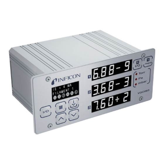
- Page 1 Operating Manual Incl. EU Declaration of Conformity Vacuum Gauge Controller VGC083A, VGC083B tinb29e1-c (2019-10)
-
Page 2: Product Identification
INFICON cannot assume responsibility or liability for any actual use based on the examples and diagrams. No patent liability is assumed by INFICON with respect to use of information cir- cuits, equipment, or software described in this manual. -
Page 3: Liability And Warranty
Labels may be located on or inside the device to alert people that dangerous voltages may be present. Liability and Warranty INFICON assumes no liability and the warranty is rendered null and void if the end- user or third parties • disregard the information in this document •... -
Page 4: Table Of Contents
Contents Product Identification Validity Important User Information Liability and Warranty 1 Introduction / General Information 1.1 VGC083A 1.2 VGC083B 2 Technical Data 3 Important Safety Information 3.1 Safety Precautions - General 3.2 Safety Precautions - Service and Operation 3.3 Electrical Conditions 3.3.1 Proper Equipment Grounding... - Page 5 Convection Gauge 9 Communication Protocol (Serial Interface) 9.1 Device Specific Serial Communication Info 9.2 INFICON RS232 / RS485 Command Protocol Summary 9.3 INFICON RS232 and RS485 Command Protocol Summary 9.4 RS232 GP 307 and 358 Protocol 9.5 RS485 GP 307 and 358 Protocol 9.6 RS232 and RS485 GP 350 Protocol...
-
Page 6: Introduction / General Information
PGE050 convection gauge please refer to the PGE050 Operating Manual. Read the Operating Manuals in their entirety for any device you intend to connect to the VGC083A prior to connecting and using the external devices and cables that the VGC083A is intended to be used with. -
Page 7: Vgc083B
The Vacuum Gauge Controller VGC083B is a vacuum pressure measurement system which is comprised of the following: The VGC083B Vacuum Gauge Controller • One INFICON BAG051 nude or BAG052 / 053 glass I R Bayard-Alpert hot • cathode ionization gauge or other equivalent brands of I... -
Page 8: Technical Data
VGC083A (IG) powers & operates one INFICON BAG050 nude UHV EB-Degas B-A hot cathode or other equivalent brands or INFICON BAG055 Mini IG (CG) powers & operates up to 2 INFICON PGE050 ® convection or Granville-Phillips (GP) ® Convectron VGC083B (IG) powers &... - Page 9 Analog input one 0 … 10 V (dc) analog input signal from a CDG when used as an alternate gauge to CG2, or analog input from one of the following INFICON modules: PGE300, PGE500, BAG302 Serial communications Protocol RS485 / RS232 - ASCII protocol...
- Page 10 Used with BAG055 20 … 28 V (dc), 36 W protected against power reversal and transient over-voltages Connectors IG & CG gauge cable assemblies provided by INFICON Digital I/O 9-pin D-sub male Serial communications RS232 9-pin D-sub female...
-
Page 11: Important Safety Information
3 Important Safety Information INFICON has designed and tested this product to provide safe and reliable service, provided it is installed and operated within the strict safety guidelines provided in this manual. Please read and follow all warnings and instructions. - Page 12 Turn off power to the unit if a cable or plug is damaged or the product is not operat- ing normally according to this instruction manual. Contact qualified INFICON ser- vice personnel for any service or troubleshooting condition that may not be covered by this operating manual.
-
Page 13: Electrical Conditions
3.3 Electrical Conditions WARNING! When high voltage is present in any vacuum system, a life threat- ening electrical shock hazard may exist unless all exposed electrical conductors are maintained at earth ground potential. This applies to all products that come in contact with the gas contained in vacuum chambers. -
Page 14: Gases Other Than Nitrogen / Air
Nitrogen / air without referring to correction factor data tables. INFICON gauges and modules are calibrated for direct readout of nitrogen or air. Do not attempt to use with other gases such as argon (Ar) or carbon dioxide (CO unless you have applied correction factors to both the displayed pressure and the analog output to determine the true measured pressure. -
Page 15: Installation
Optional EIA-standard, 19-inch, 2U height rack mount panels are available from INFICON. The optional rack mount panels are provided with panel cut- outs and mounting holes to allow efficient mounting of your VGC083 unit. - Page 16 Single cut-out panel All dimensions in inches. The single cut-out and dual cut-out rack mountable panels shown above are availa- ble from INFICON. Panel color matches the front panel of VGC083 units. Screws for mounting to rack enclosure are included. tinb29e1-c (2019-10) VGC083A_B.om...
-
Page 17: Mechanical Installation - Ionization Gauge
4.1.3 Mechanical Installation - Ionization Gauge VGC083A The VGC083A can operate one INFICON BAG050 nude UHV EB-degas Bayard-Alpert hot cathode ionization gauge or other brands of equivalent nude UHV EB-degas B-A gauges or or INFICON BAG055 Mini IG. VGC083B The VGC083B can operate... -
Page 18: Electrical Installation
Mount the PGE050 with port down, if possible, to help minimize the effect of any particles or condensation from collecting in the gauge. Do not mount the PGE050 where it will be subjected to excessive vibration. Vibra- tions may cause unstable readings, measurement errors and possible mechanical stress to components in the PGE050. -
Page 19: Installation
4.2.2 Installation A good, recommended practice is to remove power from any cable prior to con- necting or disconnecting it. The electrical connections for the VGC083 are located on the back panel of the device as shown below. 4.2.3 Connecting the Ionization Good, recommended practice is to remove power from any cable prior to connect- Gauge Cable ing or disconnecting it. -
Page 20: Standard Nude, Glass And Mini Ig Cables
Mini IG Cables VGC083A For the nude or Mini IG, connect the IG cable (PN → 85) at the VGC083A controller as described in the previous page. After installing the nude IG head on your vacuum system, connect the head end of the IG cable as shown below. -
Page 21: Bakeable Nude Ig Cable
VGC083A controller. When using the bakeable IG cable (PN → 85) connect the VGC083A to BAG050 or equivalent Nude EB- degas IG head according to wire colors listed below. -
Page 22: Standard Nude Ig Cable Connector Pin Out
Bakeable Cable wiring information below). All other cables listed above are rated BAG055 Mini IG for 50 °C ambient temperature. All IG cables provided by INFICON can be used with either single or dual filament ion gauges and filament switching is controlled from the VGC083B controller. -
Page 23: Connecting The Pge050 - Connectors Labeled "2" And "3
DE-9 D-subminiature connector to VGC083 and PGE050 connectors to "2" or "3". For your reference, the wiring chart for the PGE050 cable provided by INFICON is shown below. In addition to INFICON provided standard cable assembly lengths, INFICON will provide custom length cable assemblies upon request. -
Page 24: Power Connection
The VGC083 requires an input power of 20 … 28 V (dc), 200 W to operate. One each 2-contact pluggable terminal strip mating connector is provided for connection to the power contactors. Optional power supplies are also available from INFICON (PN → 85). -
Page 25: Digital I/O Connection
When using a capacitance manometer / diaphragm gauge or INFICON modules such as the PGE300, PGE500, BAG302 as an ALTERNATE GAUGE, the gauge must be connected to the VGC083 as shown below. The alternate gauge must be provided power from an auxiliary power supply capable of providing the power re- quired by the alternate gauge connected to the VGC083. -
Page 26: Rs232 / Rs485 Serial Communications Connection
1. RS485 with address, start and stop characters and command/response syntax derived from the INFICON BAG302 IG protocol. 2. RS232 with start and stop characters, but no addressing is used. The syntax is the same as the RS485 protocol. - Page 27 9-contact (DE-9S) D-subminiature RS232 Connections Socket Description RS232 Connector No connection Transmitted Data (OUT) Received Data (IN) No connection Signal Ground No connection No connection No connection No connection Connect either RS232 or RS485 cable to VGC083 - DO NOT CONNECT BOTH AT THE SAME TIME 9-pin (DE-9P) D-subminiature RS485 Connections Description...
-
Page 28: Operation - Ig And Cg
For example, if an applica- tion requires that pressure measurements be performed by the ion gauge from pressures lower than VGC083A: 5.00 × 10 Torr up to 1.00 × 10 Torr VGC083B: 1.00 × 10 Torr up to 1.00 ×... -
Page 29: Ig Over Pressure Shut Down
Good vacuum practice is to use a separate pressure gauge such as INFICON's PGE050 convection gauge to know when to turn on the ion gauge fila- ment. -
Page 30: Ig Over Temperature Shut Down
The information presented in sections 5.1 through 5.6, above, is intended as an introduction to the programming capabilities of the VGC083 for use in controlling the selectable parameters and functions of the BAG050 IG (VGC083A), BAG051, BAG052/053 IG (VGC083B) and PGE050 heads. -
Page 31: Setup And Programming
6 Setup and programming 6.1 Applying Power Before you turn on power to the VGC083 for the first time, ensure the cables from the VGC083 to the BAG05x nude on Mini and PGE050 convection gauges are connected and secured. Turn on power by pressing the Power key. 6.2 Front Panel Display Display - Pressure Measure- The VGC083 provides three independent front panel LED displays:... -
Page 32: User Interface Basics
6.3 User Interface Basics The setup and programming of the VGC083 controller is done via the four pro- gramming-keys located below the OLED setup screen on the left hand side of the VGC083 front panel. During programming of the VGC083, the OLED display will identify what function each key represents. - Page 33 IG CONTROL [Factory default = MANUAL MODE] • • CAL FACTORS [Factory default = C0, C1, C2, C3, C4, C5 all factory-set to 50] (VGC083A - future use only) ION GAUGE EMISS SELECT [Factory default = IE = 100UA] •...
-
Page 34: Programming
6.5 Programming NOTE The VGC083A/B controller is shipped from the factory with the ION GAUGE menu default parameters for the nude or glass IG. If you are using the BAG055 Mini IG, connect the Mini IG cable at the controller first, turn power on, access the SETUP UNIT Menu and set "DEFAULTS". -
Page 35: Setup Unit
• ITI LOG IG7V is reserved for future use. Currently not applicable. • Select ITI LOG IG if you are using INFICON's ionization gauge module such as the BAG302 IG with a Log-linear analog output. • Select ITI NON-LINEA if you are using INFICON's convection gauge modules such as the PGE300 or PGE500 with a non-linear analog output. -
Page 36: Ion Gauge
Example - To perform ALT GAUGE CAL if ALT GAUGE menu is selected for ITI LOG CG, ITI LOG IG or ITI NON-LINE. When using other INFICON vacuum gauge modules such as PGE300, PGE500 or BAG302 as alternate gauges to CG2, the analog output signals from these devices can be used to display pressure in the CG2/ALT display channel. - Page 37 EMISS SELECT [Factory default = IE = 100UA] For BAG050 / 051 / 052 / 053 Use the Up and Down key to select emission current to 100 μA, 4 mA, 10 mA, AUTO IE 100-4, AUTO IE 100-10. Then press ENTER to save setting. The selec- tion of 100 μA, 4 mA, 10 mA results in operation of the unit with a fixed emission current throughout the measurement range.
- Page 38 (sensor) sensitivity described above. Failure to ensure that the VGC083A is programmed for the actual sensitivity of the head it is used with may result in pressure readings that are not true pressure. Equipment...
- Page 39 This setting can be useful for compensating the readout of pressure when measured by the ion gauge for gases other than nitrogen/air. Consult reachus@inficon.com for further discussion on the use of this setting for compensated readings.
- Page 40 Do not change CAL FACTORS values. This menu is intended for future enhance- ment of the VGC083A capabilities. Leave C0, C1, C2, C3, C4, and C5 CAL FACTORS values at the factory default setting of 50. Changing these values to a number other than 50 will result in inaccurate vacuum pressure measurements.
-
Page 41: Convec Gauge
This programming menu allows the user to set the atmospheric pressure reading (also known as the "span" adjustment) and vacuum reading ("zero" point) for con- vection gauges CG1 and CG2. INFICON advises that you first determine if the "span" (ATM) adjustment of your measurement device is set properly before set- ting the "zero"... -
Page 42: Relays
6.5.4 RELAYS Press the ENTER key to access the RELAYS menu for configuring the setpoint relays. ASSIGN REL 1 [Factory default = ION GAUGE] This assigns Relay #1 to the ion gauge, CG1, CG2 or ALT GAUGE (alternate gauge). ASSIGN REL 2 [Factory default = CG1] ASSIGN RELAY 2;... - Page 43 REL 4 LO TRIP [Factory default = 1.00E-06] (RELAY 4 LO TRIP; same info as RELAY 1 LO TRIP above) REL 4 HI TRIP [Factory default = 2.00E-06] (RELAY 4 HI TRIP; same info as RELAY 1 HI TRIP above) REL 5 LO TRIP [Factory default = 1.00E-01] (RELAY 5 LO TRIP;...
-
Page 44: Analog Output
ALT LINEAR Linear analog output for alternate gauge only ALT CG 1-8V Log-linear analog output if alternate gauge connected is an INFICON PGE300 or PGE500 ALT IG LOGN10 Log-linear analog output if alternate gauge connected is an INFICON BAG302 CG1 1 - 8V... - Page 45 INFICON convection gauges such as the PGE300 or PGE500 provide this capability. If you are using a...
- Page 46 V is the output signal in volts. Select "ALT IG LOGN10" only if you have selected ANALOG INPUT in the SET CG2 - ALT menu intended for use with an INFICON BAG302 ionization vacuum gauge module as an alternate gauge to CG2. Essentially, this allows retransmis- sion of the same analog input signal being received from the BAG302.
- Page 47 Select "CG1 NON - LIN" as the analog output type to set the analog output (non- linear) voltage proportional to the pressure measured by convection gauge CG1. This produces a non-linear analog output signal of 0.375 to 5.659 V (dc) for 0 to 1000 Torr of N , roughly in the shape of an "S"...
- Page 48 Torr is 7.881 V. Use the UP or DOWN keys in the AOUT CAL 1 screen to set the analog output to 7.881 V as recorded by your voltmeter. Alternatively, if the CG1 analog output is used to display the CG1 pressure on your PLC or system display console, simply adjust the AOUT CAL 1 while the gauge is exposed to atmosphere so that the CG1 atmospheric pressure displayed by your PLC matches the CG1 atmospheric pressure displayed by the VGC083.
-
Page 49: Serial Comm
The VGC083 supports six different protocols listed below (See section 9 for details). • RS485 RS485 with start and stop characters and address, derived from INFICON BAG302 • RS232 RS232 with start and stop characters, like RS485 above but no address •... - Page 50 SCREEN SAVER menu and change setting to OFF and then ON again. This initiates the screen saver function immediately. NOTE To increase longevity of the OLED display, INFICON recommends that the screen saver function remains ON as shipped from the factory. BRIGHTNESS...
-
Page 51: Analog Output Charts & Equations (Nitrogen/Air Only)
7 Analog Output Charts & Equations (Nitrogen/Air Only) This section provides various charts & equations for analog outputs available from the VGC083. 7.1 Analog Output wide When the analog output is setup, as described in section 6.5.6 for IG - CG1/CG2/ALT 0.5-7V, the analog output voltage represents a combination of the range measurement for IG and CG1 or IG and CG2 or IG and ALT gaue for wide range measurements. -
Page 52: Analog Output For Ig Log N - 10 (Nitrogen / Air Only)
7.2 Analog Output for IG When the analog output is setup, as described in section 6.5.6 for IG LOG N - 10, the analog output voltage represents the pressured measured by the IG for nitro- LOG N - 10 (Nitrogen / gen/air only. -
Page 53: Analog Output For Ig Log N - 11 (Nitrogen / Air Only)
7.3 Analog Output for IG When the analog output is setup, as described in section 6.5.6 for IG LOG N - 11, the analog output voltage represents the pressured measured by the IG for nitro- LOG N - 11 (Nitrogen / gen/air only. -
Page 54: Analog Output For Ig Log N - 12 (Nitrogen / Air Only)
7.4 Analog Output for IG When the analog output is setup, as described in section 6.5.6 for IG LOG N - 12, the analog output voltage represents the pressured measured by the IG for nitro- LOG N - 12 (Nitrogen / gen/air only. -
Page 55: Analog Output For Ig 1.8 - 8.7 V (Nitrogen / Air Only)
7.5 Analog Output for IG 1.8 When the analog output is setup, as described in section 6.5.6, for IG 1.8 – 8.7V, the analog output voltage represents the pressured measured by the IG for nitro- - 8.7 V (Nitrogen / Air gen/air only. -
Page 56: Analog Output For Ig Linear (Nitrogen / Air Only)
7.6 Analog Output for IG When the analog output is setup, as described in section 6.5.6, for IG LINEAR, the analog output voltage represents the pressure measured by the IG for nitrogen/air LINEAR (Nitrogen / Air only. The Linear analog output type provides a 0-10 V (dc) output signal that has a only) direct linear relationship to the displayed pressure measured by the ion gauge only. - Page 57 Pressure Voltage Pressure Voltage Pressure Voltage [Torr] [Torr] [Torr] 1.00E-04 1.000 2.00E-01 4.301 3.00E+02 7.477 2.00E-04 1.301 5.00E-01 4.699 4.00E+02 7.602 5.00E-04 1.699 1.00E+00 5.000 5.00E+02 7.699 1.00E-03 2.000 2.00E+00 5.301 6.00E+02 7.778 2.00E-03 2.301 5.00E+00 5.699 7.00E+02 7.845 5.00E-03 2.699 1.00E+01 6.000...
-
Page 58: Analog Output For Cg1 Or Cg2 0 - 7 V (Nitrogen / Air Only)
7.8 Analog Output for CG1 When the analog output is setup, as described in section 6.5.6, for CG1 0 – 7 V or CG2 0 – 7 V, the analog output voltage represents the pressure measured by CG1 or CG2 0 - 7 V (Nitrogen or CG2 for nitrogen/air only. -
Page 59: Analog Output For Cg1 Or Cg2 Non - Lin (Nitrogen / Air Only)
7.9 Analog Output for CG1 When the analog output is setup, as described in section 6.5.6, for CG1 NON - LIN or CG2 NON - LIN, the analog output voltage represents the pressure measured by or CG2 NON - LIN CG1 or CG2 for nitrogen/air only. - Page 60 Pressure Voltage Pressure Voltage Pressure Voltage [Torr] [Torr] [Torr] 0.000 0.3751 1.00E-01 0.8780 2.00E+02 5.0190 1.00E-04 0.3759 2.00E-01 1.1552 3.00E+02 5.1111 2.00E-04 0.3768 5.00E-01 1.6833 4.00E+02 5.2236 5.00E-04 0.3795 1.00E+00 2.2168 5.00E+02 5.3294 1.00E-03 0.3840 2.00E+00 2.8418 6.00E+02 5.4194 2.00E-03 0.3927 5.00E+00 3.6753...
-
Page 61: Analog Output For Cg1 Or Cg2 Linear (Nitrogen / Air Only)
7.10 Analog Output for CG1 When the analog output is setup, as described in section 6.5.6 , for CG1 LINEAR or CG2 LINEAR, the analog output voltage represents the pressure measured by or CG2 LINEAR the CG1 or CG2 for nitrogen/air only. The Linear analog output type provides a 0- (Nitrogen / Air only) 10 V (dc) output signal that has a direct linear relationship to the displayed pres- sure measured by the CG1 or CG2 only. -
Page 62: Using The Gauge With Different Gases
8 Using the Gauge with Different Gases The following tables and explanation contain important information regarding the use of ionization and convection gauges when used to measure pressure of gases other than nitrogen /air. For both types of gauge heads, corrections must be applied to both the display and analog outputs. -
Page 63: Effects Of Different Gases On Convection Gauge Display
Since different gases, and mixtures, have different ther- mal conductivities, the indicated pressure readings and outputs will also be differ- ent. INFICON convection gauges (and most other thermal, heat loss type gauges) are normally calibrated using nitrogen. When a gas other than N... - Page 64 CAUTION! Do not assume this data applies to other convection gauges which may or may not be the same. See Table 1 below and note the following examples: Example A: If the gas is nitrogen (N2), when the true total pressure is 500 Torr, the gauge will read 500 Torr.
- Page 65 The table below shows the convection gauge displayed readings at various pressures for several commonly used gas types: True Pressure Freon12 Freon22 (Torr) 1.00E-4 1.00E-4 1.00E-4 1.00E-4 1.00E-4 1.00E-4 1.00E-4 1.00E-4 1.00E-4 1.00E-4 1.00E-4 1.00E-4 2.00E-4 2.00E-4 2.00E-4 2.00E-4 2.00E-4 2.00E-4 2.00E-4 2.00E-4...
-
Page 66: Effects Of Different Gases On Analog Output
8.3 Effects of Different The following tables and explanation contains important information regarding the use of ionization and convection gauges on gases other than N / Air. For both Gases on Analog Output types of gauges, corrections must be applied to the analog outputs. 8.3.1 Ion Gauge Analog Output When using any of the analog outputs assigned to ion gauge only, use the Correction Factors for... - Page 67 C) Apply the gas correction factor for the particular gas you are using to the pressure value obtained in step A (Use correction factors and example listed below). Ion Gauge Gas Correction Factors for selected gases CorrectionFactor Correction Factor 0.18 1.12 0.30 1.16...
-
Page 68: Ig-Cg1 0.5 - 7V Analog Output Correction Factors - Convection Gauge Range
8.3.2.2 IG-CG1 0.5 - 7V Analog When using the IG - CG1 or IG - CG2 analog output mode (Log-Linear 0.5 - 7 V, Output Correction Factors 0.5 V/decade) for gases other than N / Air, use the following look-up table and - Convection Gauge information to convert the analog output to pressure when operating in the pres- Range... -
Page 69: Cg1 1 - 8 V Or Cg2 1 - 8 V Analog Output Correction Factors - Convection Gauge
8.3.3.1 CG1 1 - 8 V or CG2 1 - 8 V When using the Log-Linear convection gauge analog output mode (Log-Linear Analog Output Correction 1 - 8 V, 1 V/decade) for gases other than N / Air, use the following look-up table Factors - Convection and information to convert the analog output to pressure. -
Page 70: Cg1 0 - 7 V Or Cg2 0 - 7 V Analog Output Correction Factors - Convection Gauge
8.3.3.2 CG1 0 - 7 V or CG2 0 - 7 V When using the Log-Linear convection gauge analog output mode (Log-Linear Analog Output Correction 0 - 7 V, 1 V/decade) for gases other than N / Air, use the following look-up table Factors - Convection and information to convert the analog output to pressure. -
Page 71: Convection Gauge
8.3.3.3 CG1 NON-LIN or CG2 When using the Non-Linear convection gauge analog output mode for gases other NON-LIN Analog Output than N / Air, use the following look-up table and information to convert the analog Correction Factors - output to pressure. The look-up table has been derived from the equation provided Convection Gauge in section 7.9 True... -
Page 72: Communication Protocol (Serial Interface)
Communication Info sub-sections of this chapter can be used to establish serial communications with the device. Six distinct protocols (COMM type) are defined: INFICON RS232 and RS485 protocol, RS232 and RS485 protocols compatible with GP series 307 and 358 controllers, and RS232 and RS485 protocols compatible with GP series 350 controllers. -
Page 73: Inficon Rs232 And Rs485 Command Protocol Summary
Response is 13 characters including carriage return. All pressure measurement responses are in absolute pressure units as selected by the user. Please see qualifying notes at bottom of table. Table "INFICON RS232 and RS485 Command Protocol Summary" COMMAND BRIEF DESCRIPTION... - Page 74 Table "INFICON RS232 and RS485 Command Protocol Summary" (continued) COMMAND BRIEF DESCRIPTION COMMAND SYNTAX RESPONSE - EXAMPLES READ all Process Read the current state of all #xxRL<CR> *xx_003F_RL_<CR> Control (PC, or process control setpoint e.g.: #01RL<CR> In the example response above,...
- Page 75 Table "INFICON RS232 and RS485 Command Protocol Summary" (continued) COMMAND BRIEF DESCRIPTION COMMAND SYNTAX RESPONSE - EXAMPLES SET EMISSION Choose 10 mA, 4mA or #xxSEy<CR> xx_PROGM_OK<CR> Current 100uA emission current e.g.: #01SE1<CR> When in Auto I mode: where, y=1=4mA; y=0=100μA ?01_INVALID_<CR>...
- Page 76 Table "INFICON RS232 and RS485 Command Protocol Summary" (concluded) COMMAND BRIEF DESCRIPTION COMMAND SYNTAX RESPONSE - EXAMPLES READ IG EMISSION Read the actual IG emission #xxRDIGE<CR> *xx_y.yyEzpp<CR> CURRENT current being measured by (e.g.: #01RDIGE<CR>) (eg: *01_1.00E-04<CR>) the gauge When IG is off: *01_0.00E+00...
-
Page 77: Rs232 Gp 307 And 358 Protocol
9.4 RS232 GP 307 and 358 RS232 protocol compatible with the GP Series 307 and 358 VGC is as defined in the following table. Please see qualifying notes at bottom of table. Protocol Table "RS232 GP 307 and 358 Protocol" COMMAND BRIEF DESCRIPTION COMMAND SYNTAX... -
Page 78: Rs485 Gp 307 And 358 Protocol
Table "RS232 GP 307 and 358 Protocol" (concluded) COMMAND BRIEF DESCRIPTION COMMAND SYNTAX RESPONSE - EXAMPLES IG OFF Turn specified IG filament IGn_OFF<CR> <LF> OK<CR><LF> e.g.: IG1 OFF<CR><LF> e.g.: OK<CR><LF> where, When IG is already OFF: INVALID n = 1 = fil1, 2 = fil2 IG DEGAS ON Turn IG Degas ON DG_ON<CR>... -
Page 79: Rs232 And Rs485 Gp 350 Protocol
Table "RS485 GP 307 and 358 Protocol" (concluded) COMMAND BRIEF DESCRIPTION COMMAND SYNTAX RESPONSE - EXAMPLES READ CGn Read the current CG #xxDS_CGn<CR> y.yyEzpp<CR> pressure in units of Torr only e.g.: #01DS CG1<CR> where, y.yy = mantissa, z = sign of the exponent +/- where, and pp = the exponent n = 1 or 2 (CG1 or CG2) - Page 80 Table "RS232 and RS485 GP 350 Protocol" COMMAND BRIEF DESCRIPTION COMMAND SYNTAX RESPONSE - EXAMPLES READ IGx Read the current IG #xxRDx<CR> *_y.yyEzyy<CR> pressure, 1=fil1, 2=fil2, no (e.g.: #01RD1<CR>) (e.g.: * 1.53E-06<CR>) char=active fil When IG is off: * 9.90E+09 READ CGx Read the current CG #xxRDx<CR>...
-
Page 81: Service
10 Service 10.1 Calibration Every INFICON module is calibrated prior to shipment using nitrogen. Care should be exercised when using gases other than nitrogen (N ) / air (see previous sections regarding the use of gases other than N /air). -
Page 82: Troubleshooting - Ig Error Messages
Replace the Ion gauge sensor tube System pressure too high Reduce pressure LV Failure The Filament voltage could not be estab- Contact INFICON lished; Electronics Failure F1 or F2 OPEN Filament 1 or 2 is open Switch to the other filament or replace the... - Page 83 From the collector current measured, which is directly proportional to the gas den- sity inside the ion gauge head enclosure, the pressure inside the ion gauge head can be calculated. The Research display screen is a very useful diagnostic tool to troubleshoot issues with the sensor or the electronics.
-
Page 84: Maintenance
10.6 Maintenance In general, maintenance is not required for your INFICON ion gauge module, con- vection gauge and control unit. Periodic performance checks may be done by com- paring the gauge to a known reference standard. When using the head in gases... -
Page 85: Repair
11 Repair Return defective products to your nearest INFICON service center for repair. INFICON assumes no liability and the warranty is rendered null and void if repair work is carried out by the end-user or by third parties. 12 Accessories... -
Page 86: Storage
13 Storage Caution Electronic components. Inappropriate storage (static electricity, humidity etc.) may damage electronic components. Store the product in an antistatic bag or container. Observe the rele- vant specifications under Technical Data (→ 10). 14 Disposal WARNING Substances detrimental to the environment. Products or parts thereof (mechanical and electric components, operating fluids etc.) may be detrimental to the environment. -
Page 87: Eu Declaration Of Conformity
EU Declaration of Conformity We, INFICON, hereby declare that the equipment mentioned below complies with the provisions of the Directive relating to electromagnetic compatibility 2014/30/EU and the Directive on the restriction of the use of certain hazardous substances in electrical and electronic equipment 2011/65/EU. - Page 88 LI–9496 Balzers Liechtenstein Tel +423 / 388 3111 Fax +423 / 388 3700 reachus@inficon.com Original: English www.inficon.com...
Need help?
Do you have a question about the VGC083A and is the answer not in the manual?
Questions and answers