
Related Manuals for Inficon CU1000


Summary of Contents for Inficon CU1000
- Page 1 Translation of the Original CU1000 Operating unit Catalog No. 560-320 From software version jina54en1-06-(1901) 2.72 (LDS3000) / 2.72 (CU1000)
- Page 2 INFICON GmbH Bonner Strasse 498 50968 Cologne, Germany...
-
Page 3: Table Of Contents
4.3 Technical data ............................ 9 5 Installation .............................. 10 5.1 Connecting the control unit ........................ 10 5.2 Installing the control unit ......................... 11 6 Operation CU1000............................ 12 6.1 Touchscreen elements ........................... 12 6.1.1 Measurement display elements .................... 12 6.2 Elements of the error and warning display ..................... 15 6.3 Settings and functions .......................... 16... - Page 4 Table of Contents INFICON 7 Decommissioning the measuring instrument.................... 29 7.1 Disposing of the device........................... 29 7.2 Sending in the device .......................... 29 8 Appendix................................. 31 8.1 CE Declaration of Conformity ......................... 31 8.2 RoHS .............................. 32 CU1000-operating-instructions-jina54en1-06-(1901)
-
Page 5: About These Instructions
Imminent hazard resulting in death or serious injuries WARNING Hazardous situation resulting in potential death or serious injuries CAUTION Hazardous situation resulting in minor injuries NOTICE Hazardous situation resulting in damage to property or the environment CU1000-operating-instructions-jina54en1-06-(1901) 5 / 36... -
Page 6: Safety
► Define responsibilities, authorizations and supervision of personnel. 2.3 Operator requirements ► Read, observe and follow the information in these instructions and the working instructions created by the owner, especially the safety instructions and warnings. 6 / 36 CU1000-operating-instructions-jina54en1-06-(1901) -
Page 7: Shipment, Transport, Storage
Transport in unsuitable packaging material can damage the device. ► ► Transport the device only in the original packaging. ► ► Keep the original packaging. Storage ► Store the device taking into consideration the technical data, refer to Chapter 4.3, page 10. CU1000-operating-instructions-jina54en1-06-(1901) 7 / 36... -
Page 8: Description
Display is set to power saving mode Fig. 2: Rear view Rating plate with control unit Calibration button for calibrating the touch screen (LCD-CAL), can be operated with touch PIN Connection for headphones Connection for the cable to the leak detector (LD) 8 / 36 CU1000-operating-instructions-jina54en1-06-(1901) -
Page 9: Function
2000 m Max. relative humidity above 40 °C Max. relative humidity from 31 °C to 40 80% to 50% (linear abfallend) °C Max. relative humidity to 40 °C Storage temperature -20 °C - 60 °C Pollution degree CU1000-operating-instructions-jina54en1-06-(1901) 9 / 36... -
Page 10: Installation
The data cable on the control unit can also be connected or removed during operation. ► If needed, connect headphones or speakers to the headphones symbol. DANGER Hearing damage from loud volume setting Loud volume setting can damage hearing. ► Do no set volume of headphones too loud. 10 / 36 CU1000-operating-instructions-jina54en1-06-(1901) -
Page 11: Installing The Control Unit
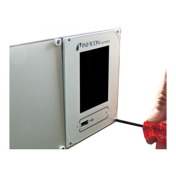
Fig. 3: Dimensions of the control unit in mm (inches in brackets) • Recess for the control unit integrated in the test system. ► Push the control unit into the recess and screw it tight. ► Pull protection film from touch screen. CU1000-operating-instructions-jina54en1-06-(1901) 11 / 36... -
Page 12: Operation Cu1000
6 | Operation CU1000 INFICON 6 Operation CU1000 NOTICE Damage to touch screen from incorrect operation. The touch screen can be damaged with a hard or pointed item. ► Operate touch screen with fingers only. 6.1 Touchscreen elements 6.1.1 Measurement display elements Fig. 4: Measurement display... - Page 13 INFICON Operation CU1000 | 6 Keyboard lock Communication status Data recording Operator Zero Message Tracer gas Operation mode Leak rate with peak hold function 10 Graphic representation of the leak 11 Time axis 12 Foreline pressure rate and the peak hold function 13 Button "Favorite 2"...
- Page 14 6 | Operation CU1000 INFICON 6 - Caution icon Active warnings are stored in the unit. The active warnings can be displayed via the menu "Info > History > Warnings". 7 - Tracer gas Set tracer gas and tracer gas concentration percentage.
-
Page 15: Elements Of The Error And Warning Display
INFICON Operation CU1000 | 6 14 - Button "Favorite 1" You can assign preferred parameters to this button (see Page 19 ). In Fig. 4 the button "Favorite 1" is assigned the function "ZERO" for example. 15 - Icon for the menu All functions and parameters of the control unit can be accessed using the "Menu"... -
Page 16: Settings And Functions
6 | Operation CU1000 INFICON 6.3 Settings and functions Settings and functions of the control unit are explained in the following. You will find the settings and functions of the mass spectrometer module LDS3000 you can set using the control unit in the operating instructions of the mass spectrometer module. - Page 17 INFICON Operation CU1000 | 6 Display units Device of pressure Mbar Torr Control unit Display > Units (display) > Pressure unit Measured value Type of graphic display display Diagram Bar graph Control unit Display > Measurement view > Measurement view mode...
- Page 18 6 | Operation CU1000 INFICON View settings Control unit Settings > Favorites > Favorite 1 (2, 3) Display of messages Warnings and error messages can be displayed on the touch screen. on the touch screen Control unit Settings > Set up > Control unit > Messages > Show...
-
Page 19: Operator Types And Authorizations
INFICON Operation CU1000 | 6 Pinpoint: The sound of the acoustic signal changes its frequency within a specific range of leak rates. Range: A decade below the selected trigger threshold up to one decade above. The sound keeps at a constant low and a constant high frequency below and above this range, respectively. - Page 20 Control unit Function > Data > Parameters > Load Save parameters The parameters of control unit CU1000 and of the mass spectrometer module can be saved to a USB flash drive. Control unit Function > Data > Parameters > Save Display error The type of error information can be set differently for each operator type.
-
Page 21: Logging Out The Operator
INFICON Operation CU1000 | 6 6.3.2.1 Logging out the operator The operator activates access level "Viewer" to log out. "Access Ctrl > Viewer" 6.3.3 Functions 6.3.3.1 Resetting the settings Mass spectrometer The settings of the mass spectrometer module can be reset to factory settings. -
Page 22: Calling Up Information
6 | Operation CU1000 INFICON Control unit Functions > Data > Recorder > Settings > Record interval Memory location The data stored in the control unit can be saved to a USB stick. The memory in the control unit is limited to the recording of a 24-hour measurement. - Page 23 INFICON Operation CU1000 | 6 • Maintenance, maintenance history Control unit • Version control unit: Information on the software version • Memory: Information on available memory • Settings: Control unit settings. • Serial port wired: Information on the communication connection •...
- Page 24 6 | Operation CU1000 INFICON Fig. 5: I/O module (2): Visualized information to the digital inputs Input signal condition Configured function (INV = Function is inverted) Status of the function (active or inactive) • I/O module (3): Visualized information to the digital outputs...
- Page 25 INFICON Operation CU1000 | 6 Fig. 6: Visualized information to the digital outputs Configured function (INV = Output signal condition Function is inverted) Status of the function (active or inactive) • Bus module (1): Information on the bus module • Bus module (2): Information on the bus module, continued...
-
Page 26: Updating The Software
6 | Operation CU1000 INFICON 6.3.4 Updating the software Software updates from INFICON are installed with the aid of a USB flash drive. The update function of the device can be found under "Functions > Data > Update". An update is possible, •... -
Page 27: Updating The Software Of The I/O Module
INFICON Operation CU1000 | 6 Copy the file Flash_LDS3000_MSB_Vxx.xx.xxx.bin into the main directory of a USB flash drive. Connect the USB flash drive to the USB port on the device. Select: "Functions > Data > Update > MSB". ð The display shows information on the current and the new software version as well as on the boot loader. - Page 28 6 | Operation CU1000 INFICON Fig. 7: DIP switch on the I/O module 28 / 36 CU1000-operating-instructions-jina54en1-06-(1901)
-
Page 29: Decommissioning The Measuring Instrument
ð You will then receive a return number from us. Use the original packaging when returning. Before sending the device, attach a copy of the completed contamination declaration. See below. CU1000-operating-instructions-jina54en1-06-(1901) 29 / 36... - Page 30 7 | Decommissioning the measuring instrument INFICON 30 / 36 CU1000-operating-instructions-jina54en1-06-(1901)
-
Page 31: Appendix
INFICON Appendix | 8 8 Appendix 8.1 CE Declaration of Conformity CU1000-operating-instructions-jina54en1-06-(1901) 31 / 36... -
Page 32: Rohs
8 | Appendix INFICON 8.2 RoHS 32 / 36 CU1000-operating-instructions-jina54en1-06-(1901) - Page 33 INFICON Appendix | 8 CU1000-operating-instructions-jina54en1-06-(1901) 33 / 36...
- Page 34 8 | Appendix INFICON 34 / 36 CU1000-operating-instructions-jina54en1-06-(1901)
Need help?
Do you have a question about the CU1000 and is the answer not in the manual?
Questions and answers