
Related Manuals for Inficon IC6


Summary of Contents for Inficon IC6
- Page 1 Cover Page Thin Film Deposition Controller IPN 074-505-P1E...
- Page 3 Title Page Thin Film Deposition Controller IPN 074-505-P1E ® www.inficon.com re achus@inficon.com ©2012 INFICON...
- Page 4 All other brand and product names are trademarks or registered trademarks of their respective companies. Disclaimer The information contained in this Operating Manual is believed to be accurate and reliable. However, INFICON assumes no responsibility for its use and shall not be liable for any special, incidental, or consequential damages related to the use of this product.
- Page 5 In additional to this file, technical, installation, maintenance and application information concerning this equipment can also be found in the Operating Manual(s) for this product or product family. Equipment Description: IC6 Deposition Controller (including all options). Applicable Directives: 2006/95/EC (LVD) 2004/108/EC (General EMC)
- Page 6 Authorized Representative: Steve Schill Thin Film Business Manager INFICON Inc. ANY QUESTIONS RELATIVE TO THIS DECLARATION OR TO THE SAFETY OF INFICON'S PRODUCTS SHOULD BE DIRECTED, IN WRITING, TO THE VICE-PRESIDENT OF OPERATIONS AT THE ABOVE ADDRESS. Revised 12/24/08 (Rev B)
- Page 7 Seller product was not designed nor against any defects due to plans or instructions supplied to Seller by or for Buyer. This manual is intended for private use by INFICON® Inc. and its customers. Contact INFICON before reproducing its contents.
-
Page 9: Table Of Contents
How To Contact INFICON ........ - Page 10 IC6 Installation ........
- Page 11 IC6 Operating Manual Chapter 3 Operation Front Panel Controls......... . . 3-1 Rear Panel Interfaces.
- Page 12 IC6 Operating Manual 3.3.11 Maintenance..........3-24 3.3.12...
- Page 13 IC6 Operating Manual Source Set-Up Introduction ........4-4 4.2.1...
- Page 14 Protocol ........... 10-5 10.3.1.1 Command Packet (Host to IC6 Message) ......10-5 10.3.1.2 Response Packet (IC6 to Host Message) .
- Page 15 Remote Layer Action ........10-52 10.4.35 IC6 Communications Examples ....... . 10-54 10.4.35.1 General Command Packet Format.
- Page 16 IC6 Cygnus Emulation ........
- Page 17 IC6 Operating Manual 11.4.2 Configure Sources 1 to 6 ........11-8 11.4.3...
- Page 18 Troubleshooting the IC6 ........
- Page 19 IC6 Operating Manual 15.9.1.4 System Diagnostics Pass But Crystal Fail Message Remains....... . . 15-37 15.9.2...
- Page 20 IC6 Operating Manual This page is intentionally blank. TOC - 12...
-
Page 21: Introduction And Specifications
Introduction and Specifications 1.1 Introduction The IC6 is a closed loop process controller designed for use primarily in physical vapor deposition. The IC6 monitors and/or controls the rate and thickness of the deposition of thin films. Deposition rate and thickness are inferred from the frequency change induced by mass added to a quartz crystal. -
Page 22: Ic6 Safety
When using this manual, please pay attention to the Notes, Cautions, and Warnings found throughout. For the purposes of this manual they are defined as follows: NOTE: Pertinent information that is useful in achieving maximum IC6 efficiency when followed. CAUTION Failure to heed these messages could result in damage to the IC6. -
Page 23: General Safety Information
IC6 Operating Manual 1.2.2 General Safety Information WARNING - Risk Of Electric Shock Do not open the IC6 case! There are no user-serviceable components within the IC6 case. Dangerous voltages may be present whenever the power cord or external input/relay connectors are present. -
Page 24: Earth Ground
IC6 Operating Manual 1.2.3 Earth Ground The IC6 is connected to earth ground through a sealed three-core (three-conductor) power cable, which must be plugged into a socket outlet with a protective earth terminal. Extension cables must always have three conductors including a protective earth terminal. -
Page 25: Main Power Connection
IC6 Operating Manual 1.2.4 Main Power Connection WARNING - Risk Of Electric Shock This IC6 has line voltage present on the primary circuits whenever it is plugged into a main power source. Never remove the covers from the IC6 during normal operation. -
Page 26: How To Contact Inficon
1.3.1 Returning Your IC6 Do not return any component of your IC6 to INFICON without first speaking with a Customer Support Representative. You must obtain a Return Material Authorization (RMA) number from the Customer Support Representative. -
Page 27: Ic6 Specifications
IC6 Operating Manual 1.4 IC6 Specifications 1.4.1 Measurement Crystal Frequency ....6.0 MHz (new crystal) to 4.5 MHz Internal Precision ....±0.0035 Hz over 100 ms sample for fundamental and anharmonic frequencies Thickness &... -
Page 28: Ic6 Features
IC6 Operating Manual 1.4.3 IC6 Features 1.4.3.1 Recipe Storage & Datalogging USB Memory Device 1.4.3.2 Sensor Parameters Up to 8 sensors can be averaged together (Sensor) Shutter Output ..0 to 38 Sensor Type . -
Page 29: Material Parameters
IC6 Operating Manual 1.4.3.4 Material Parameters 32 materials can be specified and given unique names (15 character max.). Density ..... . . 0.100 to 99.999 gm/cc Z-ratio . - Page 30 IC6 Operating Manual Idle Ramp..... 1 per Source Idle Power ....0.00 to 99.99% Idle Ramp Time .
-
Page 31: Process Layer Parameters
IC6 Operating Manual Backup Sensor ....0 to 8 Backup Tooling ....1.0 to 999.9% (Crystal) Quality Percent . - Page 32 IC6 Operating Manual LCD Dimmer Time ....0 for Always On or # of Minutes till Off 0 to 99 minutes Graph Scale ....Power, +/-10 Å/s, +/-20 Å/s Graph Scan Rate .
-
Page 33: Display
IC6 Operating Manual 1.4.4 Display Type/Color/Size ....LCD/Color/TFT/7 inch diagonal Dimming Feature ....Always Full on or Full on when in use. -
Page 34: Dac Outputs
IC6 Operating Manual 1.4.5 DAC Outputs Quantity and Type ....6 with BNC, 6 optional with 15 pin miniature D-sub providing analog outputs for Rate and Thickness. -
Page 35: Logic Processing
Hierarchy ..... Statements evaluated in numerical order at 10 Hz any time the IC6 is on. Partitioning ....None Initialization. -
Page 36: Remote Communications
1.4.8 Remote Communications RS232C Serial Port ... . . Standard; INFICON binary protocol Baud Rates ....115,200, 57,600, 38,400, 19,200, 9,600 Ethernet . -
Page 37: Size
IC6 Operating Manual 1.4.14 Size Not including mounts or user connectors 5.25 in. H x 17.625 in. W x 13 in. D (133.4 mm H x 447.7 mm W x 330 mm D) Including mounts, but no user connectors 5.25 in. H x 19 in. W x 13 in. D (133.4 mm H x 482.6 mm W x 330 mm D) -
Page 38: Unpacking And Inspection
1.6 Parts and Options Overview 1.6.1 Base Configurations IC6 Control Unit ....781-500-G1 North America, 781-500-G2 Europe Ship Kit..... . . 781-020-G1 North America, 781-020-G2 Europe Operating Manual on CD ROM . -
Page 39: Optional Accessories
Function ....Power Increase/Decrease/Stop/ Switch Crystal Adapter Cables IC6 to IC/4 Kit ....600-1084-P1 (Relays and Inputs - for IC/4 or IC/4 PLUS) 1.6.4 Oscillator Packages IC6 Oscillator, 15 ft. -
Page 40: Initial Power-On Verification
IC6 Operating Manual 1.7 Initial Power-On Verification A preliminary functional check of the IC6 can be made before formal installation. It is not necessary to have sensors, source controls, inputs or relays connected to do this. For more complete installation information, refer to... - Page 41 IC6 Operating Manual Confirm that AC line voltage is supplied and proper for the IC6. Confirm that the back panel (main) AC switch is in the ON position. Press the ON/STBY button on the front panel. A green pilot light should be seen next to the power switch.
- Page 42 IC6 Operating Manual This page is intentionally blank. 1 - 22...
-
Page 43: Installation And Interfaces
The choice of sensor type must be dictated by the Process, the deposition material and the physical characteristics of the process chamber. General guidelines for each sensor type produced by INFICON are outlined in the Sensor Data Sheets on www.inficon.com website. - Page 44 IC6 Operating Manual Figure 2-1 Typical installation Mounting Bracket Coax Cable (Routed with Water Tubes) Sensor Shutter Brazing Adapters Source to Sensor Customer Supplied 10" Minimum Cajon Coupling Source Shutter Source Pneumatic Actuator Source Controller Water In Water Out IPN 750-420-G1...
- Page 45 IC6 Operating Manual Generally, install the sensor as far as possible from the evaporation source (a minimum of 10 in. (25.4 cm) is recommended) while still being in a position to accumulate thickness at a rate proportional to accumulation on the substrate.
-
Page 46: Ic6 Installation
IC6 Operating Manual 2.1.3 IC6 Installation The IC6 is designed to be rack mounted. It may be also used on a table. The IC6 is forced-air cooled, with the air flow exiting the rear of the IC6 for clean room convenience. -
Page 47: Connections To Earth Ground
There are two required earth ground connections: The earth ground connection on the IC6 is a threaded stud with a hex nut. Connect a ring terminal to the ground strap, thus allowing a good connection and easy removal and installation. This connection must be made at installation. -
Page 48: Minimizing Noise Pickup From External Cabling
Vacuum System 2.2.3 Minimizing Noise Pickup From External Cabling When a IC6 is fully integrated into a deposition system, there can be many wire connections, each a potential path for electrical noise to reach the inside of the IC6. The likelihood of these wires causing a problem can be greatly diminished by adhering to the following guidelines. -
Page 49: Connecting The Controller
The IC6 is initially powered by AC line current. The line voltage provided in your facility must be within the voltage range of 100-230 V (ac) +/-15% V (ac). -
Page 50: Crucible Indexer Connections
Closed 2.3.2.3 DAC Option Kit 781-504-G1 An optional Digital to Analog Converter (DAC) card can be installed into the IC6. This card provides six additional DAC outputs, numbered 7 through 12, for Thickness and/or Rate as determined by the DAC Output Option parameters. The... -
Page 51: I/O Expansion Options
IC6 Operating Manual 2.3.2.4 I/O Expansion Options One I/O Relay module is included as standard equipment with the IC6 and is used to interface with other machinery of the vacuum system. It can control components such as heaters, rotators or shutters through its 8 relays. It can respond to external instructions through its 14 isolated input lines. - Page 52 IC6 Operating Manual Table 2-3 Input/Relay pin connections I/O Board #1 I/O Board #2 Relay # Pins Relay # Pins Input # Input # 7, 6 7, 6 9, 8 9, 8 11, 10 11, 10 13, 12 13, 12...
-
Page 53: Rs-232C Communications
2.3.2.5 RS-232C Communications RS-232C serial communication is included in the IC6 as standard equipment. It can be used to remotely control or monitor the IC6. An industry standard 9-pin D-Sub connector is required for the host computer side connection. Depending on the computer source, all connections may not be necessary. -
Page 54: Isolated +24 V (Dc) Supply
2.3.2.6 Isolated +24 V (dc) Supply An isolated +24 V (dc) power supply is available on a 9-pin D-Sub connector on the IC6 back panel. This supply is rated for 1.75 Amps maximum. The pin assignments for this connector are shown in Table 2-5. -
Page 55: Operation
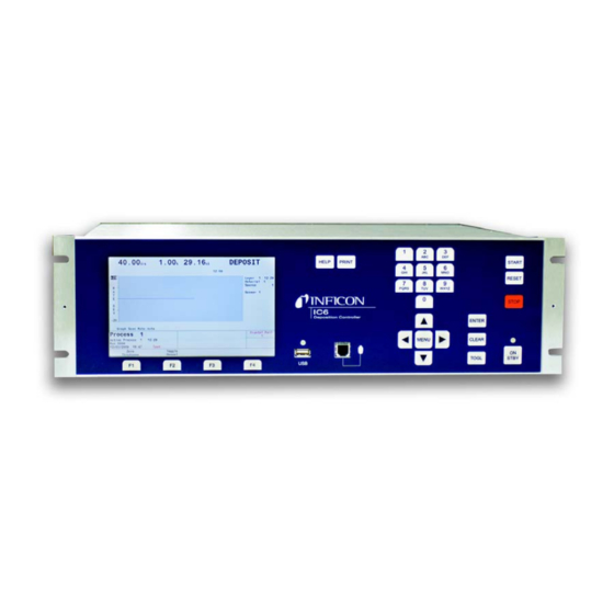
IC6 Operating Manual Chapter 3 Operation 3.1 Front Panel Controls Operational controls for the IC6 are located on the front panel, see Figure 3-1. Figure 3-1 IC6 front panel LCD Screen Provides graphical displays, set-up menus, status and error messages. - Page 56 An array of five keys used to move the display cursor either up, down, left or right. The MENU key is used to navigate through the IC6 displays. The keys auto-repeat; the cursor will continue to move as long as the key is held down.
-
Page 57: Rear Panel Interfaces
IC6 Operating Manual 3.2 Rear Panel Interfaces Interfaces for the IC6 are located on the rear panel, see Figure 3-2. Figure 3-2 IC6 rear panel Ground Stud Refer to section 2.2.2, Connections to Earth Ground, on page 2-5. AC Power Inlet, Fuse & Mains Switch Provides a common connector for international plug sets. - Page 58 Provides recorder output for six channels (15 pin miniature D-sub connector). Outputs are programmable for recorder function. 13 Fan Outlet Exhaust opening for the IC6’s miniature fan; Do not block! 14 24-Volt Supply (standard) Provides three 24 V (dc) supplies rated at 1.75 Amps. See Table 2-5 on page 2-12.
-
Page 59: Displays
IC6 Operating Manual 3.3 Displays The IC6 has many display screens for monitoring and programming processes. The six main types of displays are: Operate, Sensor, Source, Material, Process, and General. To move from one display to another, use the cursor and MENU keys. -
Page 60: Operate
IC6 is in Test mode. Status messages are displayed as long as a status is true. They are put up and taken down as the condition that set them changes. - Page 61 IC6 Operating Manual Operate Display Description Aggregate Rate Layer Thickness Power Level State of Layer State Timer Layer Currently In Process Layer Timer Material Being Deposited Source Number In Use 10 Sensor Number(s) In Use 11 Crystal Position In Use 12 Graphical Display of Rate Deviation or Power 13 Process Being Executed &...
- Page 62 IC6 Operating Manual In addition to the standard operational screen, if the system is configured for co-deposition, or multi-layer deposition, the operational screen will be divided to show information for all layers as shown in Figure 3-5, Figure 3-6 Figure 3-7.
-
Page 63: Sensor Information
IC6 Operating Manual Figure 3-7 6 layer display 3.3.3 Sensor Information 3.3.3.1 Sensor Information Rate/Xtal Display Description NOTE: N/A (not available) will be displayed in these fields for diabled features or for sensors not in use. Figure 3-8 Rate/Xtal display... - Page 64 Q Counts, or Clear Failed Crystals is pressed, that function will be performed on the sensor indicated by the box cursor if the IC6 is in Ready, Stop or all active layers are in Idle or Suspend. Text will only be shown for installed cards, unless you are in TEST.
-
Page 65: Crystal Life And Starting Frequency
On the Sensor Information RATE/XTAL display, crystal life is shown as a percentage of the monitor crystal’s frequency shift, relative to the 1.50 MHz frequency shift allowed by the IC6. This quantity is useful as an indicator of when to change the monitor crystal to safeguard against crystal failures during deposition. -
Page 66: Function Key Selection Choices For The Sensor Information Rate/Xtal Display
The action is taken on the sensor indicated by the box cursor if the IC6 is in Ready, Stop or all active layers are in Idle or Suspend. Failed crystal numbers are shown in the Failed column under Crystal. -
Page 67: Sensor Information Type/Freq Display Description
Sens indicates the last calculated Auto-Z value (prior to failure) is used for thickness calculations for this sensor. The IC6 determines to use Matl or Sens depending on the frequency of the fundamental resonance. If the fundamental frequency closely matches the last valid fundamental frequency prior to Auto-Z failure, the IC6 will use the Sens value. -
Page 68: Test Xiu
IC6 Operating Manual Act(ivity) Activity is a measure of the sensor circuit health or ability to conduct current. The values range from a maximum of 800 (healthiest) to a minimum of 0 (least healthy). The Activity value is useful for predicting when a crystal needs to be replaced. - Page 69 IC6 Operating Manual Figure 3-10 Sensor overview display Moving the cursor onto one of the sensor numbers and pressing F1 Select Sensor brings up the Sensor display section 4.1.2, Sensor Parameters, on page 4-2 for programming details. 3 - 15...
-
Page 70: Source
IC6 Operating Manual 3.3.5 Source The Source Overview display, see Figure 3-11, shows the current configuration for all six sources. Figure 3-11 Source overview display Once the right cursor key has been used to move to one of the six sources, the Select Source function key will appear. -
Page 71: Material
IC6 Operating Manual 3.3.6 Material This display is organized into eight sub pages accessible thru the Select Menu described below. Chapter 5, Material Set-Up for programming details and screen displays. 3.3.6.1 Overview Page The Material Overview display, see Figure 3-12, shows all 32 available materials. -
Page 72: Pre/Post Page
IC6 Operating Manual material. If Multipoint is set to No, a Backup Sensor and its Tooling factor can be specified. Other choices will be shown according to the Sensor Type. If the sensor is a XtalTwo, the Tooling factor for the secondary crystal can be specified. In the case of a multi-position rotary sensor head, the range of crystal positions to use can be specified. -
Page 73: Lib A-Hf, Lib Hf-Sc, Lib Sc-Z Sub-Displays
IC6 Operating Manual 3.3.6.6 Lib A-Hf, Lib Hf-Sc, Lib Sc-Z Sub-Displays These three libraries allow convenient selection of a material by its chemical formula along with the correct density and Z-Ratio values. Cursor to a Material formula, then press F1 Define Material to select that material. The Material/Source display will be shown where the remaining parameters can be entered. -
Page 74: Current Process
IC6 Operating Manual 3.3.7.2 Current Process The Curr(ent) Proc(ess) display, see Figure 3-15, shows the layer sequence for the last process edited, not necessarily the Active Process. A 15 character name can be entered here by cursoring to the Name and using the keys in cell phone style to enter characters and numbers. - Page 75 IC6 Operating Manual Figure 3-16 Process page Active Process ....specify which of the 50 processes to execute. Layer To Start ....when Start is initiated, this layer # will be executed.
-
Page 76: Dacs Page
IC6 Operating Manual 3.3.8.2 DACs Page Polarity and full scale voltage for all DAC outputs are configured here. 0 output corresponds to 0 Volts. See section 7.3, DACs Page Parameters, on page 7-3. 3.3.8.3 Comm Page Datalogging of crystal data is enabled here and RS232 and optional Ethernet parameters are entered. -
Page 77: Audio/Visual Page
IC6 Operating Manual 3.3.8.8 Audio/Visual Page Audio Feedback: turns key beep on or off. LCD Dimmer Time: 0 disables, sets time in minutes for screen to be turned off after no keys pressed. section 7.9, AUDIO / VISUAL Page Set Up, on page 7-10. -
Page 78: Logic
IC6 Operating Manual Figure 3-18 All outputs display 3.3.10 Logic 100 logic statements can be set up. Logic statements are evaluated sequentially, 10 times per second, while the IC6 is powered up. Chapter 9, Logic Statement Set-Up for programming details. 3.3.11 Maintenance The Maintenance display is organized into four subscreens: Auto Tune, Cross Talk, Source Maint(enance)and Sys(tem) Status. -
Page 79: Process Description
IC6 Operating Manual 3.4 Process Description The IC6 allows sequential deposition control for a maximum of 200 layers in all of its 50 processes. Up to six layers can be started and rate controlled at the same time. Two sequential layers can be linked as being co-deposited, enabling crosstalk correction and ratio control. - Page 80 IC6 Operating Manual Configure the sensors. Configuring the sensors involves designating whether the sensor is a single or multi-position sensor, and what output relays are connected to the sensor shutter and crystal switcher, if any. Also, the Auto-Z feature is activated or deactivated during sensor configuration.
-
Page 81: Executing A Process
The IC6 will not allow certain parameters to be changed while executing a process. A Process is not being executed when the IC6 is in the READY state, or when the Last Layer is in the IDLE state (end of process). A Layer is not being executed when the IC6 is the READY, STOP, SUSPEND or IDLE state. - Page 82 Alternate Sequence Hand denotes key press Make sure the IC6 is in READY. If not, press STOP then RESET. Press START. Assuming there are no configuration problems, the layer to start will enter pre-deposition, and continue on through deposition and post-deposition.
-
Page 83: Pre-Conditioning A Layer
IC6 Operating Manual of critical errors. Assuming the error has been remedied, the process can be continued where it left off by pressing START. Pressing RESET will abandon the run. 3.4.3 Pre-conditioning a Layer It may be desirable to prepare a layer for deposition while the previous layer is in progress. -
Page 84: Multiple Layer Starts
IC6 Operating Manual 3.4.5 Multiple Layer Starts It is possible to run up to six layers independent of each other at the same time by pressing START six times, but ratio control and cross-sensitivity will not be active. Alternatively, two or three instances of co-deposition are also possible by pressing START two or three times, respectively. - Page 85 IC6 Operating Manual 3 - 31...
-
Page 86: State Descriptions
STATUS COMM ENCODES Source Sensor Shutter Shutter 1. READY The IC6 will accept a START command. Inactive Inactive 2. CRUCIBLE SWITCH During this state, the crucible turret is Inactive Inactive (Crucible Sw) being moved from its current position to the one called out for the given material. - Page 87 IC6 Operating Manual Table 3-2 State descriptions (continued) STATE CONDITION RELAY CONTACT REMOTE STATUS COMM ENCODES Source Sensor Shutter Shutter 12. RATE RAMP 2 Rate control, desired rate changing. [New Active Active Rate 2, Start Ramp 2, Ramp Time 2] 13.
-
Page 88: Special Features
The layer’s display is frozen at the last rate and thickness values. NOTE: In STOP or SUSPEND, the IC6 will accept a START provided a valid crystal is available for the layer(s) being started. 3.6 Special Features The IC6 has several special features to enhance the performance of the instrument. -
Page 89: Xtaltwo (Crystaltwo)
IC6 Operating Manual The IC6 is configured for a XtalSix, Xtal12 or Generic, a layer is STARTed or running, and there is at least one good crystal left in the carousel when the active crystal fails. A layer is configured with a Backup sensor, a layer is running on the primary sensor, and the last crystal of the primary sensor fails. -
Page 90: Xtalsix (Crystalsix)
IC6 Operating Manual If a crystal fail occurs while in Deposit, the IC6 will switch to the second crystal and continue. The Failed Crystal list can be cleared while in Deposit by pressing the F4 function key on the Sensor Information screen with the cursor positioned on the appropriate sensor number. -
Page 91: Generic Sensor Crystal Switching
1. This must also be done after the sensor type has been changed to Xtal12. The Rotate Head function is permitted only if the IC6 is in Ready, Stop or all active layers are in Idle or Suspend. -
Page 92: Example: Programming Turret Source Crucible Selection
3.6.2.1 Example: Programming Turret Source Crucible Selection Interfacing a turret source controller to the IC6 requires both hardware connections to the turret controller and properly defining certain IC6 parameters. -
Page 93: Auto-Z
“new” crystal range and also do not match the frequencies stored within the IC6. This results in an “unable to Auto-Z” condition because the initial frequencies of the uncoated monitor crystal are not known. -
Page 94: Auto Tune - Optimizing The Control Loop
IC6. The Handheld Controller serves as a wired remote to manually control power, switch crystals and produce a STOP. The Handheld Controller is attached to the IC6 with a modular plug to the front panel. -
Page 95: Determining Soak Power With The Handheld Controller
Test mode is active. 3.6.7.1 Standard or Time Compressed This IC6 contains a software-controlled test mode which simulates actual operation. In Time Compressed mode, all layer times are sped up so that a long process can be simulated in one tenth of the time. The purpose of the test mode is to verify basic operation and to demonstrate typical operation. -
Page 96: Advanced Test
The parameter set may be stored under a new or existing filename and retrieved from an existing file. A file containing the IC6 parameter set is referred to as a configuration file. Datalog information will be saved only if the USB Datalog Format setting in the Datalog page of the USB Storage screen is set to Comma or Page. -
Page 97: Lock And Access Codes
3.6.9 Lock and Access Codes The IC6 has several forms of protection to prevent unauthorized changing of parameters. Refer to the General setup section for a description of parameter and Program lock codes and the File Access Code. In addition, a method of locking the entire display is available through the remote communications. - Page 98 IC6 Operating Manual For the comma delimited format, all the data fields are returned for all the sensors and crystals. If a sensor is not used during the deposition, the data field will contain a zero. The following values make up the data in the datalog. The data is sent in ASCII strings when the RS-232 port is set for data logging.
- Page 99 IC6 Operating Manual 128 = Normal termination, 127 = Manual source shutter closing, 126 = Suspend) Time Power Flag (Byte) (0 = No, 1 = Yes) Power Fail Flag (Byte) (0 = No, 1 = Yes) ...
-
Page 100: Dac Monitoring
IC6 Operating Manual 3.6.11 DAC Monitoring IC6 continually compares the actual output voltages at the DAC BNC connectors with the internally generated values to detect external or internal equipment malfunction. If the values do not agree, IC6 takes the following action: If the DAC output is assigned for Source control: ... -
Page 101: Sensor & Source Set-Up
The basic IC6 has one sensor measurement board with two sensor channels, identified as CH1 and CH2 on the IC6 back panel and as Sensor # 1 and Sensor # 2 on the display screens. Three more sensor measurement boards can be added to support up to eight sensors. -
Page 102: Sensor Parameters
IC6 Operating Manual Figure 4-2 Sensor parameter editing 4.1.2 Sensor Parameters SENSOR TYPE ....Single (0), XtalTwo (1), XtalSix (2), Xtal12 (3), Generic (4). Press the TOGL key to move through the choices. - Page 103 DAC used with this sensor. Values 1 through 6 correspond to the six DAC BNC outputs on the back of the IC6 labeled DAC 1 to DAC 6. DAC outputs 7 to 12 require the optional DAC output card.
-
Page 104: Source Set-Up Introduction
IC6 Operating Manual 4.2 Source Set-Up Introduction The IC6 provides the capability to configure the six source control channels. Each source control channel is treated as an individual device. Source Set-Up is initiated by moving the cursor to the Source heading on the Main Menu and pressing MENU. -
Page 105: Source Parameters
Values range from 0 to 12, with 0 indicating there is no DAC identified with this particular source. Values 1 through 6 correspond to the six DAC BNC outputs on the back of the IC6 labeled DAC 1 to DAC 6. DAC outputs 7 to 12 require the optional DAC outputs card. - Page 106 No indicates there is no Turret Feedback. The default value is No. See the Turret Input and Turret Delay descriptions below. NOTE: If the turret feedback is set to Yes and the Process is STARTed, the IC6 will proceed to the CRUCIBLE SW state. If the turret input is not received within the Turret Delay time, the process will STOP.
-
Page 107: Dac Output Selection Rules
(Turret Feedback = Yes) this is the time the IC6 will wait to receive the input signal. If the signal is not received within this time, the IC6 will stop. If the Turret Input becomes active during the delay time, processing continues immediately. - Page 108 IC6 Operating Manual The priority of a recorder output that is in conflict is: a. Aggregate Rate/Thickness on the Primary Layer (the first of two co-deposited layers). b. Aggregate Rate/Thickness on the Secondary Layer (the second of two co-deposited layers).
-
Page 109: Material Set-Up
Material Set-Up 5.1 Introduction The IC6 can store definition parameters for up to 32 materials. Each layer in a Process references one of these materials by its number, ranging from 1 to 32. Any material that is to be used must be defined. Materials can be defined... -
Page 110: Material Definition
IC6 Operating Manual #, move the cursor to the appropriate library display: Lib A-Hf, Lib Hf-Sc or Lib Sc-Z. Press F4 to clear a Material of all programmed values. Move the cursor to a Material to be cleared. Press the "Default Material" function key F4. This will set the Material parameter values, including its name, to their dafault values. -
Page 111: Material Screen Source
IC6 Operating Manual 5.1.3 Material Screen Source Page Parameters Figure 5-3 Material source screen MATERIAL NUMBER ... 1 to 32 Change the number to edit or create a different material. - Page 112 IC6 Operating Manual CONTROL LOOP ....NonPID (0), PI (1), PID (2) The bracketed value is used for changing the setting via the remote communications commands. This parameter establishes the control loop algorithms pertaining to either a slow responding source or a fast responding source.
- Page 113 IC6 Operating Manual DEAD TIME ....0.010 to 9999.99 s This value is defined as the time difference between a change in % power and the start of an actual change in rate.
-
Page 114: Material Screen Sensor Parameters Page
Values 1 through 6 correspond to the six DAC BNC outputs on the back of the IC6 labeled DAC 1 to DAC 6. DAC outputs 7 to 12 require the optional DAC outputs card. The default value is zero for the Rate filtered for the Rate Filter Time, see section 5.1.7 on page... - Page 115 IC6 Operating Manual BACKUP SENSOR ..0 to 8 Select the sensor to use if the primary sensor fails. This parameter only appears if Multipoint has been set to No. Default is 0, which disables the function.
- Page 116 IC6 Operating Manual Table 5-1 Aggregate multiplier effect (continued) Sensor Sensor Sensor Sensor Aggregate Aggregate Condition of the Rate (Å) Multiplier deposition Rate (Å) Rate (Å) Rate (Å) Rate (Å) Applying the multiplier to all Xtal Fail 1.25 future aggregate rate results:...
- Page 117 Deposit at the same time. If this is attempted, a sensor conflict error will occur and the IC6 will enter the STOP state. If one layer is in either a pre-Deposit or post-Deposit state, and the other layer in Deposit, the layer in Deposit has use of the sensor.
- Page 118 IC6 Operating Manual (SENSOR) TOOLING ..1.0 to 999.9% The Sensor Tooling factor is used to account for the geometric tooling factor of each sensor. The default value is 100%. If the TOOLING parameter for a sensor is changed, the new TOOLING value is used for subsequent calculations of the sensor rate, and therefore the aggregate rate, if the sensor’s Failure Action is not...
- Page 119 Next, adjust this TOOLING to get agreement between the thickness measured by the IC6 and the thickness measured at the substrates. CAL THICKNESS ..0 to 999.8, 999.9 = UNCAL Calibration Thickness values are only used in co-deposition applications and do not pertain to single layer sequential deposition.
-
Page 120: Pre/Post Screen Deposit
This parameter is usually set to the power level at which the source material just begins to glow. The IC6 ramps the power level from zero to Pre-Cond Soak Power linearly over the time period Pre-Cond Rise Time. The default value is 0. - Page 121 This parameter is usually set to the power level at which the source material just begins to melt. The IC6 ramps the power level from zero or Precon Soak level if programmed to Soak Power 1 linearly over the time period Rise Time 1.
- Page 122 CONTROL DELAY TIME ..00:00 to 99:59 This is the time interval for the IC6 to be held in the Control Delay state. The parameter is displayed only if the Delay Option chosen is Control or Both. The default value is 00:00.
-
Page 123: Post Deposit Parameters
DEPOSIT state to the Feed Power level. Feed Power is held constant until the end of Feed Time. At the end of Feed Time, the IC6 will proceed to the Idle ramp state. Source and sensor shutter are inactive. -
Page 124: Deposit
IC6 Operating Manual Power level. The control voltage is maintained at the Idle Power level until the IC6 enters the STOP state or until the next layer, using the specified source, is started, or the turret source is rotated. IDLE POWER ....0.0 to 99.99% This value is the power level at which the source is maintained after the DEPOSIT state (or after Feed state if one is set up). - Page 125 IC6 Operating Manual The Rate Filter Time may be used for enhanced resolution. If a source has a long time constant, rate may be taken as constant over longer intervals Averaging provides an opportunity to reduce rate noise. Depending on the source of the noise, averaging can improve rate resolution: ...
- Page 126 IC6 Operating Manual CAUTION The Sensor must be positioned so the rate can be monitored with the source shutter closed when going to the non-deposit control state. RAMP 1 RATE ....0.000 to 999.9 Å/s Rate Ramp 1 is provided to effect an aggregate rate change while depositing a Layer.
- Page 127 A five second time delay for thermal stabilization occurs between opening the shutter and taking measurements. During this time, DELAY is displayed in the IC6 message area. The RateWatcher Sample phase uses the measured deposition rate to control the source power.
- Page 128 IC6 Operating Manual RateWatcher OPTION... No (0), Yes (1) Default is No (0) which disables the function and greys out the Time and Accuracy parameters. RateWatcher TIME ... . . 00:00 to 99:59 min:s Ratewatcher Time determines the time interval between sample periods.
-
Page 129: Process Set-Up
Process Set-Up 6.1 Process Set-Up Introduction The IC6 is capable of storing the descriptions and parameters for up to fifty processes. Processes can consist of up to 200 sequential layers of materials. If more layers are required, another process can be started automatically. A layer or sequence of layers may be copied up to 199 times, provided the maximum number of layers is not exceeded. -
Page 130: Curr(Ent) Proc(Ess) Page
IC6 Operating Manual Processes that have at least one layer programmed are identified by a "greater than" character (>) beside the process number. Only processes with layers can be made active. The active process is shown in the status area. When Start is initiated, the layer sequence in that process will be executed. -
Page 131: Process Layers 1 - 10 Etc
IC6 Operating Manual 6.4 Process Layers 1 - 10 etc. Layers are shown in groups of 10. Moving the cursor down to one of the layer groups labeled 1 - 10 etc. in the left display pane, shows the layer parameters. -
Page 132: Layer Parameters
IC6 Operating Manual To insert, first move the cursor to the layer in which to place the tagged layers. This can be in the current process or any other process. Then, press F2 Insert Layer and the tagged layers will be inserted into the process. The insert will be done the number of times (#) entered into the # Times To Be Copy parameter. -
Page 133: Special Layer Parameter Features
100% to be able to START the process. 6.5 Special Layer Parameter Features 6.5.1 Skip Deposit If the Final Thickness is set to 0.000 kÅ, the IC6 will skip the DEPOSIT State. State processing will go directly to the post-Deposit parameter state from the last pre-Deposit state. - Page 134 IC6 Operating Manual This page is intentionally blank. 6 - 6...
-
Page 135: General Parameters
Chapter 7 General Parameters 7.1 General Set-Up Overview The IC6 provides the capability to modify a series of top level parameters that define the controller’s method of handling system level activities. Some of the parameters are automatically incremented by the IC6. -
Page 136: Layer To Start
IC6 Operating Manual LAYER TO START....1 to 200 This selects the starting Layer from the sequence of Layers defined in the Active Process. The upper limit to the range of values is determined by the number of Layers defined for a given Process. -
Page 137: Dacs
IC6 Operating Manual ACTIVE LAYER OUTPUT ..0, 1 to 31 Specifies the first of eight consecutive outputs that indicate the active layer’s number. The outputs will change to indicate the layer number in binary mode. -
Page 138: Comm
RS-232 connector on the rear panel and press F1. Message RS-232 Test Failed or RS-232 Test Passed will appear. If the loop-back connector is not available, jumper pins 2 and 3 to perform the test. Contact INFICON Service if the RS-232 Test Failed message appears. - Page 139 Standard enables receiving communication commands from an external host and sending the expected responses. Dlog Comma and Dlog Page allow only one-way transmission of information from the IC6 to the external device. The Dlog Comma format allows importation of the Data Log string into a spreadsheet program.
-
Page 140: Message Page Set-Up
These messages are turned on and off under control of logic statements. Up to four messages can be displayed in the message area. Newer messages will displace older ones. IC6 status messages have priority and will also displace user messages. -
Page 141: Date / Time Set Up
IC6 Operating Manual 7.6 DATE / TIME Set Up Figure 7-5 General screen date/time page DATE FORMAT ....MM/DD/YYYY, DD/MM/YYYY Default is MM/DD/YYYY. Use the TOGL key to select DD/MM/YYYY. -
Page 142: Test Page Set Up
ADVANCED TEST ....On (1), Off (0) If set to On, the IC6 will respond to crystal fails and switch to backup sensors or crystal positions. A TEST will be displayed when the Advanced Test is On. -
Page 143: Lock Page Code Set-Up
Program Lock Code is locked. This allows a process recipe to be entered into the IC6 from a USB storage device without unlocking the Program Lock Code. If the File Access Code has not been enabled, USB port retrieval is not allowed when a Program Lock Code is present. -
Page 144: Audio / Visual Page Set Up
IC6 Operating Manual 7.9 AUDIO / VISUAL Page Set Up Figure 7-8 General screen audio visual page AUDIO FEEDBACK... . . Yes (1), No (0) Default is No. Yes Activates Audio Feedback, signifying keyboard interaction. -
Page 145: Digital I/O Screen
8.2 All Input Page Figure 8-1 All input page All input names assigned by the IC6 or by the user are shown to facilitate system diagnosis. Darker font color designates inputs that are currently active. 8 - 1... -
Page 146: All Output Page
IC6 Operating Manual 8.3 All Output Page Figure 8-2 All output page All output names assigned by the IC6 or by the user are shown to facilitate system diagnosis. Darker font color designates inputs that are currently active. 8 - 2... -
Page 147: I/O Board Page
IC6 has automatically assigned a name. Names created by the IC6 cannot be edited. To enter or edit a user name, move the cursor onto the appropriate input or output and use the keyboard in cell phone fashion to create or edit the name. - Page 148 IC6 Operating Manual This page is intentionally blank. 8 - 4...
-
Page 149: Logic Statement Set-Up
Logic Statement Set-Up 9.1 Logic Statement Overview The IC6 programmable logic capabilities allow it to respond to digital external inputs to control the execution of a process or series of processes without operator intervention. You can tailor these capabilities by programming the logic statements. -
Page 150: Editing The Logic Statements
I/O card, eight more relays and fourteen open collector outputs are available. The IC6 has the capacity for 100 logic statements. 9.2 Editing the Logic Statements Logic Set-Up is initiated by moving the cursor to the Logic heading on the Main Menu and pressing MENU. -
Page 151: Logic Statement Groups
IC6 Operating Manual 9.2.1 Logic Statement Groups To view logic statements in groups of four, move the cursor in the left pane down to that group. Individual statements in that group can then be edited by moving the cursor to the statement number and pressing F1 Edit, see Figure 9-3. -
Page 152: Logic Statement Editing
IC6 Operating Manual 9.2.2 Logic Statement Editing Figure 9-3 Logic event IF selection Figure 9-4 Logic action Then selection 9 - 4... - Page 153 IC6 Operating Manual While in logic-edit, the select menu area will be cleared from the screen. This allows the whole screen to be used for statement editing. A single statement is displayed to edit. The lower portion of the screen will be used to display either the event or the action list.
-
Page 154: And/Or And On Logic Connectors
IC6 Operating Manual Figure 9-5 Function keys IF/THEN, REPLACE, INSERT With the cursor in the lower half of the Event page, the F4 key will carry the Negate function in addition to the first three shown above. When moving the cursor from an event or action, the next element is a numeric field, if required. -
Page 155: If Event Definitions
IC6 Operating Manual Material, Sensor, Source, Layer End, Material End, Crystal Fail, Crystal Switching, Max Power, Min Power, Backup Sensor In Use, Crucible Switch Fail, Rate < 0.1, Transfer Sensor In Use, Auto-Z Fail, Ion-Assist, and Rate Deviation Error. There cannot be two consecutive ONs in a statement. A ON B ON C is not allowed. - Page 156 IC6 Operating Manual BKUP SENS IN USE Sets the logic condition to be true while a backup sensor is in use. The condition remains true until a backup sensor is no longer active. COMPUTER CNTRL Sets the logic condition to be true when a Set Logic Statement vvv (1 to 100) command is received from the remote communications port.
- Page 157 IC6 Operating Manual FEED RAMP Sets the logic condition to be true at the start of Feed Ramp. The condition remains true until the end of Feed Ramp. The condition is also cleared when entering the Manual state, and when a STOP/RESET or a STOP/START sequence is executed.
- Page 158 IC6 Operating Manual LAYER ### Sets the logic condition to be true at the beginning of Layer ### (when Layer ### is in the READY state at the beginning of a Process or when STARTed during a Process). The condition remains true until the layer is no longer active.
- Page 159 IC6 Operating Manual MAX POWER Sets the logic condition to be true as long as any source is at Max(imum) Power. The condition remains true until every source is less than Maximum Power. MIN POWER Sets the logic condition to be true as long as any source is at Min(imum) Power.
- Page 160 IC6 Operating Manual PRECOND SOAK Sets the logic condition to be true at the beginning of the Precond Soak state. The condition remains true until the Rise 1 or a subsequent non-zero state is entered, or until a STOP/RESET sequence is executed.
- Page 161 Manual state, and when a STOP/RESET or a STOP/START sequence is executed. READY Sets the logic condition to be true as long as the IC6 is in the READY state. The condition remains true until a START command is received or when entering Manual State.
- Page 162 Numeric inputs range from 1 through 100. STOP Sets the logic condition to be true as long as the IC6 is in STOP. The condition remains true until a RESET or a START command is received. SUSPEND Sets the logic condition to be true as long as the IC6 is in SUSPEND.
- Page 163 IC6 Operating Manual TIME LIMIT Sets the logic condition to be true once the Time Limit is achieved. The condition remains true until the Layer which has achieved Time Limit enters the IDLE state or until a STOP/RESET sequence is executed.
-
Page 164: Then Action Definitions
PreCond Soak, Rise 1, Soak 1, Rise 2, Soak 2 — and the post-deposit state Idle Ramp. For the feature to be activated the state’s timer must be non-zero. If the IC6 is in the Ready state and a Start command is executed while CLOCK HOLD is active, the IC6 will progress to the first pre-deposit state with a non-zero state time. - Page 165 This action selects which Process # is to be the Active Process. The value entered must correspond to a defined Process. If the IC6 is already executing a Process, that is, not in Ready or Idle of last layer in process when this Action is activated, the Action is ignored.
- Page 166 IC6 Operating Manual SOAK 1 HOLD (ON/OFF) ## ..0 (any material) to 32 If active (ON), the designated Material ## will pause execution and maintain Soak Power 1 until Soak Hold 1 is turned OFF. Commands from Remote Comm and Logic will be independent.
- Page 167 IC6 Operating Manual TRIG FNL THICK ## ... . 0 (any material) to 32 This action triggers Final Thickness for the designated Material ## and the layer proceeds to the Feed Ramp or Idle Ramp state. This action is ignored if not in the Deposit state.
-
Page 168: Logic Statement Example
IC6 Operating Manual 9.5 Logic Statement Example The logic statement capability of the IC6 allows for automation of a thin film process. For example, it is possible to start a process without manually pressing START. One way to accomplish this is:... - Page 169 IC6 Operating Manual To return to the OPERATE display, press Menu. To run the multilayer process, press START once. As each layer ends, the IC6 will automatically issue another START, until the LAST LAYER has completed. 9 - 21...
- Page 170 IC6 Operating Manual This page is intentionally blank. 9 - 22...
-
Page 171: Remote Communications
10.2.1 RS-232C Serial Port RS-232C serial communications are accomplished through an industry standard 9-pin female connector found on the rear panel of the IC6. A mating male connector is required for attachment of a host interface. The host and IC6 can be separated by up to fifty feet using multiconductor shielded data cable. -
Page 172: Tcp/Ip Ethernet Port
Most personal computers (PC) are configured to obtain the IP address, an address which defines the computer on the Internet, automatically from a server. To communicate directly with the IC6, the Internet protocol (IP) on the PC must be configured manually and an ethernet crossover cable (for example, IPN 600-1211-P5) must be connected between the PC and the IC6. - Page 173 IC6 Operating Manual Select the Local Area Connection to be changed, right-click and select Properties. See Figure 10-2. Figure 10-2 Local area connection properties On the General tab, select Internet Protocol (TCP/IP) and press the Properties button. See Figure 10-3.
- Page 174 IP address to use when communicating with the IC6. The IC6 is shipped from INFICON with a pre-assigned address of 10.211.72.203. To communicate directly with the IC6 from a PC, the PC must also be assigned an address that starts with 10.211.72 but cannot be set to 10.211.72.203. The...
-
Page 175: Message Format
The Standard message protocol serves as a structure for the contained command or response information. It also can provide a level of acknowledgment between the host and server and a mechanism for verifying the information content. The IC6 supports the following RS-232 protocols: Standard, Dlog Comma and Dlog Page. - Page 176 IC6 Operating Manual Checksum ....1 byte, sum, modulo 256, of all bytes, not including length. Modulo 256 is the numeric...
-
Page 177: Response Packet (Ic6 To Host Message)
IC6 Operating Manual 10.3.1.2 Response Packet (IC6 to Host Message) <Length><CCB><Timer><Response Message><Checksum> Length ..... . . Number of bytes including CCB, Timer, and Response Message. -
Page 178: Timeouts
If more than 3 seconds pass between characters of a command packet, the IC6 will time out. No response packet is sent, the IC6 will clear its buffers and assume any future characters are the beginning of a new packet. -
Page 179: Real_Xxx And Real_Xfx
IC6 Operating Manual Table 10-1 Format code (continued) Format Code Displays the value as REAL_5X3 XX.XXX REAL_6F32 XXX.XXX or XXXX.XX TIME MM:SS (Minutes:Seconds) ENCODE Displays text from a Toggle list INTEGER Whole number (no decimal point) LOCKCODE XXXX 10.3.2.1 REAL_xXx and REAL_xFx ... -
Page 180: Communication Commands
IC6 Operating Manual 10.4 Communication Commands The following only include the command portion of the command packet and the response portion of the response packet. The headers/trailers are assumed. (See section 10.3.1, Protocol, on page 10-5 for their definition.) General definitions <Float>... -
Page 181: Status Commands
10-52). Every command requires a remote code and may require a value. Command variations include: RG = Affects system or IC6 level conditions. RL = Affects conditions for a specified layer. 10.4.3 HELLO Command H <Command ID> given in hex format... -
Page 182: Update Source Parameter
IC6 Operating Manual 10.4.5 Update Source Parameter Command = UC <Command ID> <Source number> <Parameter Value> Command ID = <Byte> See Table 10-5. Source Number = <Byte> Source number 1 - 6 Parameter Value = <Integer> | <Float> Type of value depends on command ID, see Data Type column in Table 10-5. -
Page 183: Query General Parameter
IC6 Operating Manual 10.4.6 Query General Parameter Command = QG <Command ID> Command ID = <Byte> See Cmnd ID in Table 10-6 Response = <Integer> | <Float> Description = Type of response depends on command ID, see Data Type column Table 10-6. -
Page 184: Usb Datalog Format
IC6 Operating Manual Table 10-6 General parameters (continued) Range: Data Type Update Restrictions & Name and Display Notes Notes (Units) Limit/ Cmnd High Limit/ Default Not Used (0x07) Active Layer 0/ 31/ 0 Integer 0 = Off Update not allowed if... -
Page 185: Dac 1 To 12 Scale
IC6 Operating Manual Table 10-6 General parameters (continued) Range: Data Type Update Restrictions & Name and Display Notes Notes (Units) Limit/ Cmnd High Limit/ Default Graph Scan Rate 0/ 3/ 0 Encode 0 = Auto 1 = Slow (0x15) 2 = Med... - Page 186 IC6 Operating Manual Table 10-6 General parameters (continued) Range: Data Type Update Restrictions & Name and Display Notes Notes (Units) Limit/ Cmnd High Limit/ Default DAC 1 Polarity 0/ 1/ 1 Encode 0 = Negative Update not allowed if process is running.
-
Page 187: Query Input Name
Input Name = <String> Up to 15 characters, null terminated Response = None (Just header and trailer) Input Names may only be updated if the IC6 is in Ready or Stop. NOTE: UI changes are not allowed while a process is running. The UI command will not allow updating a name set by hardware designation, unless it is identical to the defined hardware name. -
Page 188: Query Logic Statement
IC6 Operating Manual 10.4.12 Query Logic Statement Command = QL <Statement Number> Statement Number = <Byte> 1 - 100 Response = <Length of logic elements> <Set of elements> NOTE: This length is NOT the same as the length of the packet. It tells how many bytes follow in the "event/action"... - Page 189 IC6 Operating Manual Event Terms First element of term can be (, a space, or an Event code . If space, there are no events, go straight to Action Terms (see below). if (, next element must be event code .
-
Page 190: Update Logic Statement
1500554C01114115264102264112264108205101410A031A Response = None (Just header and trailer) Logic changes are not allowed while a process is running or if the IC6 is in a stop. 10.4.14 IC6 Event List Events used in the Logic Statement IF section. Logic codes are used in the remote communication query and update commands. - Page 191 IC6 Operating Manual Table 10-7 Event list (continued) Events Min Max Min Max Logic Logic numeric Code Code numeric Negated (1 Byte) (Integer) (XXX) (YYY) Rise 1 0x4A 0xB6 Soak 1 0X4B 0xB5 Rise 2 0x4C 0xB4 Soak 2 0x4D...
- Page 192 IC6 Operating Manual Table 10-7 Event list (continued) Events Min Max Min Max Logic Logic numeric Code Code numeric Negated (1 Byte) (Integer) (XXX) (YYY) Source XXX Source # 0x64 0x9C Layer End XXX Layer # 0x65 0x9B 0 = Any...
- Page 193 IC6 Operating Manual Table 10-7 Event list (continued) Events Min Max Min Max Logic Logic numeric Code Code numeric Negated (1 Byte) (Integer) (XXX) (YYY) Cruc Sw Fail 0x75 0x8B Rate < 0.1 0x76 0x8A Shutter Dly Error 0x77 0x89...
-
Page 194: Ic6 Action List
IC6 Operating Manual 10.4.15 IC6 Action List Actions are triggered in the Logic Statement THEN section. Logic codes are used in the remote communication query and update commands. Some actions that require a numeric may act on all items by entering a zero, as noted in Table 10-8. - Page 195 IC6 Operating Manual Table 10-8 Action list (continued) Actions Numeric Min Max Logic (Byte) Code * Soak 1 Hold Off XXX 0x56 * Soak 1 Hold On XXX 0x57 * Soak 2 Hold Off XXX 0x58 Material # * Soak 2 Hold On XXX...
-
Page 196: Query Material Parameter
IC6 Operating Manual 10.4.16 Query Material Parameter Command = QM <Command ID> <Material Number> Command ID = <Byte> See Table 10-9 Material Number = <Byte> 1- 32 Response = <Integer> | <Float> Type of response depends on command ID, see Data Type column in Table 10-9. - Page 197 IC6 Operating Manual Table 10-9 Material parameters (continued) Range: & Name Low Limit/ Update Restrictions Notes (Units) High Limit/ Data Type and Display Notes Cmnd Default Source 1/ 6/ 1 Integer Update not allowed if (0x08) material is running. Maximum Power 0.01/...
- Page 198 IC6 Operating Manual Table 10-9 Material parameters (continued) Range: & Name Low Limit/ Update Restrictions Notes (Units) High Limit/ Data Type and Display Notes Cmnd Default Rise Time 2 (0x13) (seconds) 0/ 5999/ 0 Time (mm:ss) 0/ 99:59/ 0 See Time Note...
- Page 199 IC6 Operating Manual Table 10-9 Material parameters (continued) Range: & Name Low Limit/ Update Restrictions Notes (Units) High Limit/ Data Type and Display Notes Cmnd Default Idle Power 0.0/ 99.99/ REAL_4X2 (0x1f) Idle Ramp Time See Time Note (0x20) (seconds)
- Page 200 IC6 Operating Manual Table 10-9 Material parameters (continued) Range: & Name Low Limit/ Update Restrictions Notes (Units) High Limit/ Data Type and Display Notes Cmnd Default Ramp 2 Time See Time Note (0x2c) (seconds) 0/ 5999/ 0 Time (mm:ss) 0/ 99:59/ 0...
- Page 201 IC6 Operating Manual Table 10-9 Material parameters (continued) Range: & Name Low Limit/ Update Restrictions Notes (Units) High Limit/ Data Type and Display Notes Cmnd Default Sensor 1 (0x3a) Failure Trigger Sensor 2 (0x3b) Failure Trigger Visible only if Multipoint...
- Page 202 IC6 Operating Manual Table 10-9 Material parameters (continued) Range: & Name Low Limit/ Update Restrictions Notes (Units) High Limit/ Data Type and Display Notes Cmnd Default Sensor 1 Tooling (0x4a) Sensor 2 Tooling (0x4b) Sensor 3 Tooling (0x4c) Sensor 4 Tooling 1.0/...
- Page 203 IC6 Operating Manual Table 10-9 Material parameters (continued) Range: & Name Low Limit/ Update Restrictions Notes (Units) High Limit/ Data Type and Display Notes Cmnd Default Sensor 1 Cal (0x5a) Thickness (KÅ) Sensor 2 Cal (0x5b) Thickness (KÅ) Sensor 3 Cal (0x5c) Thickness (KÅ)
- Page 204 IC6 Operating Manual Table 10-9 Material parameters (continued) Range: & Name Low Limit/ Update Restrictions Notes (Units) High Limit/ Data Type and Display Notes Cmnd Default Sensor 1 Xtal (0x6a) Position Last Sensor 2 Xtal (0x6b) Position Last Sensor 3 Xtal...
- Page 205 IC6 Operating Manual Table 10-9 Material parameters (continued) Range: & Name Low Limit/ Update Restrictions Notes (Units) High Limit/ Data Type and Display Notes Cmnd Default Backup Sensor 0/ 8/ 0 Integer 0 = No backup sensor. Backup sensor cannot...
-
Page 206: Query Material Name
Output Name = <String> Up to 15 characters, null terminated Response = None (Just header and trailer) Output Names may only be updated if the IC6 is in Ready or Stop. NOTE: UO changes are not allowed while a process is running. The UO command... -
Page 207: Query Process Layer Parameter
IC6 Operating Manual 10.4.22 Query Process Layer Parameter Command: QP <Command ID> <Process Number><Layer Number> Command ID = <Byte> See Table 10-10. Process Number = <Byte> 1 - 50 Layer Number = <Byte> 1 - 200 Response = <Integer> | <Float>... -
Page 208: Query Sensor Parameter
IC6 Operating Manual Table 10-10 Process layer parameters (continued) Range: & Name Low Limit/ Update Restrictions Notes (Units) High Limit/ Data Type and Display Notes Cmnd Default (Crucible) 1/ 64/ 1 Integer Update not allowed if (0x04) active process is running... - Page 209 IC6 Operating Manual Table 10-11 Sensor parameters Range: & Name Low Limit/ Update Restrictions Notes (Units) High Limit/ Data Type and Display Notes Cmnd Default (Sensor) Shutter 0/ 38/ 0 Integer 0 = not defined (0x01) Out(put) Update not allowed if the sensor is running. Not...
-
Page 210: Query Output Type
IC6 Operating Manual 10.4.26 Query Output Type Command = QT <Output Number> Output Number = <Byte> 1 - 38 Response = <Output Type> Output Type = <Byte> 0 or 1 (0 = NO, 1 = NC) 10.4.27 Update Output Type Command = UT <Output Number>... -
Page 211: Status General
IC6 Operating Manual 10.4.30 Status General Command = SG <Command ID><Option> Command ID = <Byte> See Description in Table 10-12. Option = <Byte> |< Integer > | <32 Bit Word> | <48 Bit Word> Response = <Byte>… <Byte> | <Integer>…<Integer... - Page 212 IC6 Operating Manual Table 10-12 Status general commands (continued) Number Comm Description Option of bytes and ID in the Data Returned Notes response Status Messages <Byte><Byte><Byte> See encodes in section 15.1 on page 15-1. One (0x06) <Byte><Byte><Byte> bit is set for each error.
- Page 213 IC6 Operating Manual Table 10-12 Status general commands (continued) Number Comm Description Option of bytes and ID in the Data Returned Notes response Counter Value Counter <Integer> Number (0x0d) <Integer> 1 - 20 Thickness Sum Equation 4 or 12 <Float> or...
-
Page 214: Status Layer
IC6 Operating Manual 10.4.31 Status Layer Command = SL <Command ID><Layer> Command ID = <Byte> See Description in Table 10-13. Layer = <Byte>Layer number (0 – 200 or 255 (0xFF)) Layer = 0 will return the status of six layers. The response will include all active layers. - Page 215 IC6 Operating Manual Table 10-13 Status layer (continued) Number Command Description of bytes in the Data Returned Notes response Power Source 1 or 6 <Byte> Source number for the requested Number layer. (0x08) Accumulated Layer 4 or 24 <Integer> Seconds since "Ready"...
-
Page 216: Status Sensor
IC6 Operating Manual 10.4.32 Status Sensor Command = SS <Command ID><Sensor> Command ID = <Byte> See Description in Table 10-14. Sensor = <Byte> Sensor number (0 - 8) If the sensor number is zero the response will give the value for all eight sensors. - Page 217 IC6 Operating Manual Table 10-14 Status sensor (continued) Number Description of bytes Command in the Data Returned Notes response Fundamental 8 or 64 <Long> or One long integer for each sensor. Frequency Unconverted. To convert to Hz, multiply by (0x04) <Long><Long><Long>...
- Page 218 IC6 Operating Manual Table 10-14 Status sensor (continued) Number Description of bytes Command in the Data Returned Notes response (0x0b) Sensor 4 or 32 <Float> or kÅ (0x0c) Thickness Returns sensor thickness <Float><Float><Float> <Float><Float><Float> <Float><Float> Sensor Raw 4 or 32 <Float>...
-
Page 219: Remote General Action
IC6 Operating Manual 10.4.33 Remote General Action Command = RG <Command ID> (<Action Value>) Command ID = <Byte> See Table 10-15. Action Value = <Byte>… <Byte> | <Integer>…<Integer>|<Float>…<Float> Table 10-15 for commands that require an action value. Response = None (Just header and trailer) - Page 220 IC6 Operating Manual Table 10-15 Remote general (continued) Meaning Command Action Value Notes Zero Counter <Byte> Counter Range is 0-20 <Counter> (0x0b) 0 = All Zero Timer <Byte> Timer Range is 0-20 <Timer> (0x0c) 0 = All Start Timer <Byte>...
- Page 221 Rotate head X <Byte> If the requested sensor is a multi crystal sensor and the IC6 is in Ready, Stop or all active layers are in Idle or (0x1a) Suspend, the sensor head will rotate. X = Sensor Default all...
-
Page 222: Remote Layer Action
IC6 Operating Manual Table 10-15 Remote general (continued) Meaning Command Action Value Notes RateWatcher <Byte> Turns RateWatcher sampling off. Sample Initiate Off (0x24) <Material > Clear Q and S <Byte> Clear Q and S counts for specified sensor X counts for sensor X... - Page 223 IC6 Operating Manual Table 10-16 Remote layer (continued) Meaning Command Action Notes Value Go to Non-Deposit This cannot be done from Ready, Stop, Suspend or Crucible Control Switch. When there is no good crystal, this command will go (0x03) to Non-Deposit Hold if the previous state was Time Power, otherwise, is not allowed.
-
Page 224: Ic6 Communications Examples
Remember to count in hex. ASCII Name and version: Each byte represents an ASCII Checksum: 1 byte, hex sum character. Combine these characters to get "IC6 Version 0.14". of complete message The H1 command response is a string of ASCII characters. -
Page 225: Query General Parameter
IC6 Operating Manual 10.4.35.4 Query General Parameter Active Process (1) Command Format: QG <Command ID> Command QG1 = 030051470199 Response: 07000019060200000021 10.4.35.5 Update General Parameter Active Process (1), Make Process 2 active Command Format: UG <Command ID> <Paramter Value> UG1 2... -
Page 226: Update Sensor Parameter
IC6 Operating Manual 10.4.35.9 Update Sensor Parameter Sensor Type (2), Sensor 1, CrystalTwo (1) Command Format: US <Command ID> <Sensor Number> <Parameter Value> US2 1 1 Command US2 1: 08005553020101000000AC Response: 0300002F0635 10.4.35.10 Query Source Parameter Shutter Output (2), Source 1 Command Format: QC <Command ID>... -
Page 227: Update Process Layer Parameter
IC6 Operating Manual 10.4.35.13 Update Process Layer Parameter Process 1, Layer 1, Material 3 (3) Command Format: UP <Command ID><Process Number><Layer Number><Parameter Value> UP1 1 1 3 Command UP1 1 1 3: 0900555001010103000000AB Response: 03000039063F Example: UP1 1 1 3 command... -
Page 228: Query Material Name
IC6 Operating Manual 10.4.35.14 Query Material Name Material 1 Command Format: QN <Material Number> QN 1 Command QN 1: 0300514E01A0 Response: 0A0000470653494C5645520022 10.4.35.15 Update Material Name Material 1, "SILVER" Command Format: UN <Material Number> <Material Name> UN 1 SILVER Command UN 1 SILVER: 0A00554E0153494C5645520079 Response: 030000E806EE 10.4.35.16 Query Process Name... -
Page 229: Update Input Name
IC6 Operating Manual 10.4.35.19 Update Input Name Input 1, “P1” Command Format: UI <Input Number> <Input Name> UI 1 P1 Command: 060055490150310020 Response: 030000A306A9 10.4.35.20 Query Output Name Output 1 Command Format: QO <Output Number> QO 1 Command Q0 1: 0300514F01A1 Response: 0B0000E206534855545445520017 10.4.35.21 Update Output Name... -
Page 230: Query User Message
IC6 Operating Manual 10.4.35.24 Query User Message Message 1 Command Format: QV <User Message Number> QV 1 Command QV 1: 0300515601A8 Response: 0A0000C80648454C4C4F210063 10.4.35.25 Update User Message Message 1, “HELLO!” Command Format: UV <User Message Number> <User Message Name> UV 1 HELLO! -
Page 231: Update Logic Statement
Set of elements: Using the events and actions list from low end of the length character is first, the IC6 manual, construct the required logic statement. In followed by the high end (00 in this case). this case, 41 = External Input, 01 specifies input 1, 20 = Remember to count in hex. -
Page 232: Status Layer
IC6 Operating Manual 10.4.35.29 Status Layer Thickness (4), Layer 1 Command Format: SL <Command ID> <Layer> SL4 1 Command SL4 1: 0400534C0401A4 Response: 070000980689418C4236 10.4.35.30 Status Sensor Crystal Life (0), Sensor 1 Command Format: SS <Command ID> <Sensor> SS0 1... -
Page 233: Example For Interpreting Float Responses
Sent to IC6: 04,00,53,53,06,01,AD Response from IC6: 07,00,00,AA,06,1F,85,45,41,DA Float portion of response from IC6 (low to high): 1F,85,45,41 Reverse the float response, so it is now high to low: 41,45,85,1F Convert each byte to its binary equivalent (you can do this using a scientific... - Page 234 IC6 Operating Manual Rewrite each individual "1" in the value above in exponent form: 1.10001011000010100011111 x 2 = (2 ) x 2 Distribute the 2 (Add the exponents, so for example, 2 etc) : Expand the exponents in their decimal form: = 8 + 4 + 0.25 + 0.0625 + 0.03125 + 0.0009765625...
-
Page 235: Multiple Sensor Deposition Control
11.1 Multiple Sensor Deposition Control The conventional method of controlling thin film depositions is to use one crystal sensor for each material source. In addition to this conventional method, the IC6 can make use of multiple sensors for control of each material source. - Page 236 IC6 Operating Manual Figure 11-1 The essential advantage of multi-point deposition sensing 11 - 2...
-
Page 237: Ic6 Parameters And Corrections For Multiple Sensor Operation
IC6 Operating Manual 11.1.1 IC6 Parameters and Corrections for Multiple Sensor Operation Figure 11-2 Multipoint display AGGREGATE RATE The Aggregate Rate calculation is based on: The rate information acquired by each sensor in use. A weighting factor that reflects the relative importance of each sensor's information. - Page 238 IC6 Operating Manual AGGREGATE MULTIPLIER The parameter AGGREGATE MULTIPLY (Yes/No) determines whether an aggregate multiplier is calculated for this crystal's rate information if a crystal fails occurs during deposition. This parameter appears on the Material/Sensor display if Multipoint is set to Yes. This multiplier is used only during the layer in which the crystal failure occurs.
-
Page 239: Trend Analysis
0 indicates there is not a DAC identified with this particular material. Values 1 through 6 correspond to the six DAC BNC outputs on the back of the IC6 labeled DAC 1 to DAC 6. DAC outputs 7 to 12 require the optional DAC outputs card. -
Page 240: Ic6 Cygnus Emulation
IC6 Operating Manual 11.3 IC6 Cygnus Emulation The IC6 has features that allow it to meet the critical requirements of Cygnus applications in OLED manufacturing. Cygnus emulation features: ability to run up to six layers simultaneously and show rate, thickness, power... -
Page 241: Ic6 Four & Six Layer (Cygnus Emulation) Configuration
11.4 IC6 Four & Six Layer (Cygnus Emulation) Configuration NOTE: The same method applies to any smaller set of simultaneous layers. Instrument: IC6 with 3 measurement boards for six simultaneous layers or 2 measurement boards for four simultaneous layers and optional DAC Outputs card. -
Page 242: Configure Sensors 1 To 6
IC6 Operating Manual 11.4.1 Configure Sensors 1 to 6 (See section 4.1, Sensor Set-Up Introduction, on page 4-1.) Assign a unique DAC output under the Recorder Settings Output parameter to each sensor if the associated layer’s Rate, Thickness or Rate Deviation is to be monitored. -
Page 243: Configure The Process
IC6 Operating Manual 11.4.4 Configure the Process (See Chapter 6, Process Set-Up.) Assign a different one of the six unique materials defined in step 3 to layers 1 to 6. If crosstalk correction is required between two sequential layers, set the CoDep... -
Page 244: State Descriptions
11.4.7.1 NonDepCntl State Once a layer reaches its Final Thickness and enters the NonDepCntl state, Remote command (see chapter 10 in the IC6 manual) RL 2 # zeroes the layer’s thickness and reenters deposit, RL 0 # suspends the layer. -
Page 245: Maintenance And Calibration Procedures
The tooling factor can be experimentally established by following the guidelines in section 12.3 on page 12-2. In the IC6 if the Z-Ratio is not known it could be estimated from the procedures outlined in section 12.4 on page 12-3, or, typically, the Auto-Z function can be used to determine the Z-Ratio. -
Page 246: Determining Tooling
= Thickness reading on IC6 = Measured thickness A quick check of the calculated density may be made by programming the IC6 with the new density value and observing that the displayed thickness is equal to the measured thickness, provided that the IC6's thickness has not been zeroed between the test deposition and entering the calculated density. -
Page 247: Laboratory Determination Of Z-Ratio
IC6 Operating Manual 12.4 Laboratory Determination of Z-Ratio NOTE: On the IC6, the Auto-Z function is available to automatically calculate the Z-Ratio. Especially when precise Z-Ratio values are significant, Auto-Z is recommended. See section 16.1.6 on page 16-9 for a description of Auto-Z theory. - Page 248 IC6 Operating Manual Using the density value from step 1 and the recorded values for F and F adjust the Z-Ratio value in thickness equation [5] to bring the calculated thickness value into agreement with the actual thickness. If the calculated value of thickness is greater than the actual thickness, increase the Z-Ratio value.
-
Page 249: Autotuning
IC6 Operating Manual 12.5 AutoTuning The AutoTune feature of the IC6 is used to automatically characterize the response of a system. AutoTune examines the rate change response after executing step changes in power. Control parameters are calculated for algorithms designed for... - Page 250 An AUTOTUNE failure means the IC6 was unable to consistently measure the system's response characteristics. NOTE: To ensure a successful AutoTune, there are a few items to be considered: ...
- Page 251 IC6 Operating Manual The Auto Tune feature of the IC6 is accessed via the Main Menu Maintenance display. Figure 12-1 AutoTune overview The default condition is Auto Tune Disabled. To enable Auto Tune, move the cursor onto the Disabled box and press TOGL, then ENTER.
-
Page 252: Autotune Parameters
IC6 Operating Manual 12.5.2 AutoTune Parameters MATERIAL INDEX....1 to 32 This parameter is used to select the Material that is to be AutoTuned. Values range from 1 to 32. The default value is 1. -
Page 253: Autotune Manual Display
IC6 Operating Manual 12.5.3 AutoTune Manual Display The AutoTune Manual display is entered from the AutoTune Maint Stop display by selecting F1 START AUTO TUNE. To return to the AutoTune Parameters display, press F2 AUTO TUNE PARAMETERS. The AutoTune Manual display is similar to the general Operate display with the exception that Thickness and Process information will be absent. -
Page 254: Autotune Tuning Display
IC6 Operating Manual 12.5.4 AutoTune Tuning Display After a stable rate has been achieved in Manual, the AutoTune Tuning display is entered from the AutoTune Manual display by selecting F1 START TUNING. AutoTune tuning is executed automatically by the instrument. - Page 255 IC6 Operating Manual deposition exceeds the Maximum Rate value during this transition, the power level is returned to the initial power setting and the instrument will increase the power level to a value of 2.5% greater than the initial level.
- Page 256 IC6 Operating Manual Figure 12-5 AutoTune success display Figure 12-6 AutoTune complete display When AutoTune is complete, the newly calculated values will be displayed next to the old values. The user then has the option to F3 ACCEPT or F4 REJECT the new control loop values.
-
Page 257: Determining Cross Talk Calibration
12.6 Determining Cross Talk Calibration For Co-Deposition The automatic Cross Talk Calibration feature of the IC6 is beneficial to applications involving the simultaneous deposition of two materials. When depositing two materials, it is not always possible to isolate each crystal so that it samples material from a single source. -
Page 258: Procedure Set-Up
100% and the two co-deposited Layers can be STARTed. If a sensor were to fail during deposition, the IC6 will calculate new Cross Talk percentages for the "new" sensor configuration. For example, if Sensor 4 fails, the new Cross Talk percentage... - Page 259 IC6 Operating Manual entering the partially completed results is given. Only the CONTINUE setting on MAX POWER will allow the calibration to continue on reaching MAX POWER. When using a Dual Crystal Sensor it is important that the Crystal shutter be removed during calibration so that material will deposit onto both crystals.
-
Page 260: Cross Talk Calibrate Parameters
IC6 Operating Manual Figure 12-8 Cross talk maint stop display 12.6.1.2 Cross Talk Calibrate Parameters MATERIAL NUMBER ... 1 to 32 This parameter is used to select the Material to be calibrated. Values range from 1 to 32. -
Page 261: Cross Talk Calibration Manual Display
IC6 Operating Manual 12.6.2 Cross Talk Calibration MANUAL display Upon pressing the TOGGLE MANUAL function key while in MAINT STOP, the IC6 enters the Manual state, allowing manipulation of the source power level using the Hand-Held Controller. This is used to prepare the source for calibration. Bring the source power level to a point where the deposition rate is stable and approximately the rate at which you wish to calibrate. -
Page 262: Cross Talk Calibration Calibrate Display
Status error message will be given. When automatic calibration is completed the IC6 will enter a CAL RAMP Power Down state in which the source control power is ramped to Zero over the time period designated by this material's Idle Ramp Time. -
Page 263: Cross Talk Calibration Select Display
IC6 Operating Manual 12.6.4 Cross Talk Calibration SELECT display After the RAMP down state the IC6 enters the SELECT display, from which the user can accept or reject the calibration thickness values, as desired. If the values are accepted they are stored on the Material’s Sensor page. -
Page 264: Source Maintenance
IC6 Operating Manual 12.7 Source Maintenance The Source Maintenance page allows toggling source and sensor shutters and rotating the crucible indexer associated with a selected material. Source power may be manually adjusted using the hand-held controller. The unit must be in Ready mode to Enable Source Maintenance and it must be Disabled to exit back to normal operation. -
Page 265: Source Maintenance Parameters
12.7.1 Source Maintenance Parameters SOURCE MAINTENANCE ..Enabled/Disabled IC6 must be in Ready to Enable and must be Disabled to return to normal operation. Default is Disabled. MATERIAL NUMBER ... 1 to 32 While in Maint Stop, select the material associated with the source or sensor to be checked. -
Page 266: System Status
IC6 Operating Manual 12.8 System Status Figure 12-13 System status display The System Status display shows installed option boards and firmware versions. There are no user parameters. 12 - 22... -
Page 267: Counters & Timers
IC6 Operating Manual Chapter 13 Counters & Timers 13.1 Introduction The IC/6 has twenty counters and twenty timers. These counters and timers enable you to customize logic statements. Timers and counters are "up/increasing" value variables. You can increment a counter or start a timer on any event via a logic statement. - Page 268 IC6 Operating Manual This page is intentionally blank. 13 - 2...
-
Page 269: Usb Storage
USB port storage device. To prevent loss of data, no more than 500 data log files should be written to the USB device. The IC6 will only display the first 120 files (15 per page) and a message "More Files on the USB." All files will be displayed on a computer. -
Page 270: Configuration Files
IC6 Operating Manual 14.3 Configuration Files With the instrument in the READY state, the configuration of the IC6 may be sent to a storage device attached to the USB port. Configuration files will be written with the default name IC6.ISC. The configuration file can be named within the eight-character limitation that exists in the USB file handling firmware. -
Page 271: Data Logs
If a file with the same name exists, the new data log information will be appended to the existing file. The IC6 will use the .IDL extension to identify Datalog files. See Figure 14-2. -
Page 272: Screen Captures
DD = day of month, MM = month, YY = year, xx is a number that increments from 0 to 99, resetting to 0 every day. The IC6 will use the .BMP extension to identify screen capture files. The +++ indicates that additional files exist on the USB device beyond those displayed. -
Page 273: Troubleshooting, Status And Error Messages
IC6 Operating Manual Chapter 15 Troubleshooting, Status and Error Messages 15.1 Status Messages Some IC6 status messages will have designators to indicate the Material, Source or Sensor the status refers. Table 15-1 indicates designators and to what they refer. If there is a message that has multiple occurrences, it will display on one line with multiple designators after it. - Page 274 0000,0000 reaches the programmed minimum power or when the minimum power. IC6 leaves rate control. This message doesn’t appear if the Minimum power is programmed for 0.0%. X = Material Crystal Switch(ing)
- Page 275 IC6 Operating Manual Table 15-1 Status messages (continued) Status Message Cleared Screen Remote Comm. Encode Abbr(eviated) During a rate control state, a When a new layer is started. 0x0000,2000 Average X..X crystal failure occurred after Stop/Reset 0000,0000 more then one minute but...
- Page 276 IC6 Operating Manual Table 15-1 Status messages (continued) Status Message Cleared Screen Remote Comm. Encode Source Conflict When attemting to load two After a successful reset. 0x0000,0010 Codep layers during a reset 0000,0000 and both layers call for the same source.
-
Page 277: User Messages
IC6 Operating Manual 15.2 User Messages Table 15-2 messages are a subgroup of status messages. The user defines these messages. They are displayed and cleared via logic actions. The messages will display in the same screen area as other status messages. -
Page 278: Autotune And Calibration Messages
Fast System AutoTune has detected the response Exit AutoTune AutoTune mitted while of the IC6 to be fast Restart AutoTune in AutoTune. Result of speed test. Slow System AutoTune has detected the response Exit AutoTune AutoTune of the IC6 to be slow. -
Page 279: Stop Messages
IC6 Operating Manual 15.4 STOP messages When the IC6 goes into STOP, a cause of stop message appears on the line below STOP. Some of these messages will have designators to indicate the Material, Source or Sensor that caused the Stop. - Page 280 IC6 Operating Manual Table 15-4 Stop messages (continued) Cause of STOP Clear Screen Remote Message Comm. Encodes CrossTalk > 100% One or both of the co-deposited A RESET command layers has a Cross Talk received from the keyboard, percentage ≥100%.
-
Page 281: Transient Messages
IC6 Operating Manual 15.5 Transient Messages Transient messages, see Table 15-5, are displayed as the condition happens. The messages are removed from the screen on any key press or if another transient message appears. Only one transient message will be displayed at a time. These messages will appear on all screens. - Page 282 Transient Message Clear Screen Remote Comm. Encodes Datalog Failure The IC6 is sending the Datalog information The message is faster then the receiving device can accept removed from the data. The data is lost. the screen on any key press or...
- Page 283 IC6 Operating Manual Table 15-5 Transient messages (continued) Transient Message Clear Screen Remote Comm. Encodes USB (File Check Sum) The message is Storage Error: Data Corrupt removed from the screen on USB error: Bad Conf. Storage any key press or...
- Page 284 IC6 Operating Manual Table 15-5 Transient messages (continued) Transient Message Clear Screen Remote Comm. Encodes Can’t Delete: Co-Dep An attempt was made to delete one layer of The message is Process a co-dep pair of layers. removed from the screen on Can’t Insert: Co-Dep...
- Page 285 IC6 Operating Manual Table 15-5 Transient messages (continued) Transient Message Clear Screen Remote Comm. Encodes Crucible Switch Fail Crucible switch fail while in Source The message is Source Maintenance. removed from Maintenance available the screen on from any key press or...
-
Page 286: Input Error Messages
IC6 Operating Manual 15.6 Input Error Messages Keyboard Input Error Messages come up on the entry of invalid parameters. These messages will appear on the transient error message line in the message box. The font color of the parameter value being updated will change to a different color to denote an input error has been made. - Page 287 IC6 Operating Manual Table 15-6 Input error messages (continued) Input Error Message Cleared Screen Co-Dep Crosstalk Error An attempt is being made to turn on a sensor Each input error Material that will cause a Crosstalk error. message is taken down by...
-
Page 288: Troubleshooting Guide
IC6 Operating Manual 15.7 Troubleshooting Guide If the IC6 fails to work, or appears to have diminished performance, the following Symptom/Cause/Remedy charts may be helpful. CAUTION There are no user serviceable components within the IC6 case. Potentially lethal voltages are present when the line cord, Inputs or Outputs are connected. -
Page 289: Troubleshooting The Ic6
Electrical cord unplugged b. Reconnect power cord from wall or back of IC6 c. Incorrect line voltage c. Have qualified personnel verify line voltage, verify the IC6 is configured for the correct voltage 2. - Page 290 IC6 Operating Manual Table 15-7 Troubleshooting the IC6 (continued) SYMPTOM CAUSE REMEDY 6. Control voltage output a. DAC board damaged from a. Ensure cable connection does not function properly applying voltage to the to the DAC board does not control voltage output...
- Page 291 IC6 Operating Manual Table 15-7 Troubleshooting the IC6 (continued) SYMPTOM CAUSE REMEDY 9 Crystal fail message is a. XIU/oscillator not a. Verify proper always on connected sensor/oscillator connections b. XIU/oscillator b. If available, insert a known malfunctioning working XIU/oscillator in place of suspect one;...
-
Page 292: Troubleshooting Transducers/Sensors
IC6 Operating Manual 15.7.2 Troubleshooting Transducers/Sensors NOTE: Many sensor head problems may be diagnosed with a DVM (Digital Volt Meter). Disconnect the short oscillator cable from the feedthrough and measure the resistance from the center pin to ground. If the reading is less than 1-2 megohms, the source of the leakage should be found and corrected. - Page 293 RF interference from c. Verify earth ground, use sputtering power supply ground strap adequate for RF ground, change location of IC6 and oscillator cabling away from RF power lines, connect IC6 to a different power line d. Cables/oscillator not d.
- Page 294 IC6 Operating Manual Table 15-8 Troubleshooting Transducers/Sensors (continued) SYMPTOM CAUSE REMEDY 4. Crystal oscillates in a. Crystal was near the end a. Replace crystal vacuum but stops oscillation of its life; opening to air after open to air causes film oxidation which increases film stress b.
- Page 295 Cyclic change in rate d. Make certain source's sweep frequency is not "beating" with the IC6's measurement frequency 7. Large drift in thickness a. Crystal heating due to poor a. Clean or polish the crystal (greater than 200 Å...
-
Page 296: Troubleshooting Computer Communications
Improper cable a. Verify for correct cable be established between the connection wiring as described in host computer and the IC6 section 2.3.2.5 on page 2-11. b. BAUD rate in host b. Verify BAUD rate in the computer not the same as... - Page 297 D = illegal command d. The command sent is not format valid; verify command syntax as shown in the IC6 manual (placement of spaces within the command string is important) e. E = no data to retrieve e.
- Page 298 F = Cannot change value f. The command sent is for (continued) a parameter that cannot be changed while the IC6 is executing a Process; place the IC6 in the READYstate in order to change the value g. G = Bad checksum g.
-
Page 299: Replacing The Crystal
IC6 Operating Manual 15.8 Replacing the Crystal The procedure for replacing the crystal is basically the same with all transducers, except the XtalSix. CAUTION Always use clean nylon lab gloves and plastic tweezers for handling the crystal (to avoid contamination which may lead to poor adhesion of the film to the electrode). -
Page 300: Cool Drawer
IC6 Operating Manual Figure 15-1 Front load crystal sensor (exploded) Front Load Crystal Holder (IPN 750-172-G1) Crystal (IPN 008-010-G10) Fully Coated Face (Gold) Crystal Retainer (IPN 007-023) Finger Spring Contact (IPN 750-171-P1) Front Load Standard Crystal Sensor Body (IPN 750-207-G1) - Page 301 IC6 Operating Manual Hold the retainer by its sides. Align its orientation notch with the drawer then gently and evenly push the retainer down until it snaps firmly into the drawer. Figure 15-3. Never push down (or pull up) on the contact spring, doing so may permanently damage it.
-
Page 302: Shuttered And Dual Sensors
IC6 Operating Manual 15.8.3 Shuttered and Dual Sensors There is no difference in the crystal replacement procedure between shuttered and non-shuttered Front Load sensors, since the shutter pivots away from the crystal opening when the shutter is in the relaxed state. This is also the case for Cool Drawer Sensors as the shutter assembly does not obstruct the drawer from being inserted into the sensor body. -
Page 303: Sputtering Sensor
IC6 Operating Manual 15.8.5 Sputtering Sensor Observe the general precautions for replacing crystals and follow the instructions below to replace the crystal in a sputtering sensor. Grip the body assembly with your fingers and pull it straight out to separate it from the water-cooled front cover. -
Page 304: Crystal Snatcher
IC6 Operating Manual 15.8.6 Crystal Snatcher Use the crystal snatcher, supplied with the sensor, as follows: Insert crystal snatcher into ceramic retainer (1) and apply a small amount of pressure. This locks the retainer to the snatcher and allows the retainer to be pulled straight out (2). -
Page 305: Crystal Sensor Emulator Ipn 760-601-G1 Or 760-601-G2
IPN 760-601-G1 or 760-601-G2 NOTE: Crystal Sensor Emulator 760-601-G1 (obsolete) is not compatible for use with an IC6, IC5 and IC4. 760-601-G2 is fully compatible with all Thin Film Deposition Controllers. The Crystal Sensor Emulator option is used in conjunction with the Thin Film Deposition Controller to rapidly diagnose problems with the Deposition Controller's measurement system. -
Page 306: Diagnostic Procedures
IC6 Operating Manual 15.9.1 Diagnostic Procedures The following diagnostic procedures employ the Crystal Sensor Emulator to analyze a constant Crystal Fail message. The symptom is a Crystal Fail message that is displayed by the Deposition Controller even after the monitor crystal has been replaced with a new good monitor crystal. -
Page 307: Feedthrough Or In-Vacuum Cable
IC6 Operating Manual 15.9.1.2 Feedthrough Or In-Vacuum Cable Diagnostic Procedure Refer to Figure 15-8 on page 15-33. Remove the in-vacuum cable from the Sensor Head at point B. Connect the Crystal Sensor Emulator to the in-vacuum cable. If the Crystal Fail message disappears after approximately five seconds, the feedthrough and in-vacuum Cable are working properly. -
Page 308: Sensor Head Or Monitor Crystal Diagnostic Procedure
There must be electrical isolation between the center pin of the Microdot connector and the Sensor Head body. If the Sensor Head is found to be defective, contact INFICON to have the Sensor Head repaired. 15 - 36... -
Page 309: System Diagnostics Pass But Crystal Fail Message Remains
The Crystal Sensor Emulator contains a quartz crystal having a fundamental frequency at 5.5 MHz. With the Crystal Sensor Emulator connected, the % XTAL Life display should read approximately 30% for IC6 deposition controllers which allow a 1.5 MHz frequency shift. -
Page 310: Sensor Cover Connection
Cool Drawer Dual Sensor Head CDD-XXXX Crystal12 Sensor Head XL12-XXXXXX RSH-600 Sensor Head 15320X-XX NOTE: The Crystal Sensor Emulator’s Sensor Cover will not fit the crystal holder opening of the older style INFICON transducers that have the soldered finger springs. 15 - 38... -
Page 311: Specifications
IC6 Operating Manual 15.9.4 Specifications Dimensions 1.58 in. diameter x 1.79 in. (40.13 mm diameter x 45.47 mm) Temperature Range 0 to 50 Frequency 760-601-G1: 5.5 MHz ± 30 ppm at room temperature 760-601-G2: 5.5 MHz ± 1 ppm at room temperature Materials 304 Stainless Steel, Nylon, Teflon, brass. - Page 312 IC6 Operating Manual This page is intentionally blank. 15 - 40...
-
Page 313: Measurement And Control Theory
IC6 Operating Manual Chapter 16 Measurement and Control Theory 16.1 Basics The Quartz Crystal deposition Monitor, or QCM, utilizes the piezoelectric sensitivity of a quartz monitor crystal to added mass. The QCM uses this mass sensitivity to control the deposition rate and final thickness of a vacuum deposition. When a voltage is applied across the faces of a properly shaped piezoelectric crystal, the crystal is distorted and changes shape in proportion to the applied voltage. -
Page 314: Monitor Crystals
IC6 Operating Manual effect provides a means of determining how much material is being deposited on a substrate in a vacuum system, a measurement that was not convenient or practical prior to this understanding. 16.1.1 Monitor Crystals No matter how sophisticated the electronics surrounding it, the essential device of the deposition monitor is the quartz crystal. - Page 315 IC6 Operating Manual reduces the intensity of response of the generally unwanted anharmonic modes; hence, the potential for an oscillator to sustain an unwanted oscillation is substantially reduced. Figure 16-2 Frequency response spectrum 1000 Frequency (in MHz) The use of an adhesion layer has improved the electrode-to-quartz bonding, reducing “rate spikes”...
-
Page 316: Period Measurement Technique
IC6 Operating Manual Figure 16-3 Thickness shear displacement displacement node 16.1.2 Period Measurement Technique Although instruments using equation [2] were very useful, it was soon noted they had a very limited range of accuracy, typically holding accuracy for DF less than 0.02 F... -
Page 317: Z-Match Technique
IC6 Operating Manual monitor crystal’s period is (n/F )/m where n is the number of counts in the second accumulator. The precision of the measurement is determined by the speed of the reference clock and the length of the gate time (which is set by the size of m). -
Page 318: Active Oscillator
IC6 Operating Manual for a number of materials, and has been found to be valid for frequency shifts equivalent to F = 0.4F . Keep in mind that equation [2] was valid to only 0.02F equation [3] was valid only to ~0.05F 16.1.4 Active Oscillator... -
Page 319: Modelock Oscillator
Figure 16-5 Crystal frequency near series resonance point 16.1.5 ModeLock Oscillator INFICON created a new technology that eliminates the active oscillator and its limitations. This new system constantly tests the crystal’s response to an applied frequency in order to not only determine the resonant frequency, but also to verify that the crystal is oscillating in the desired mode. - Page 320 IC6 Operating Manual measurement system uses the phase/frequency properties of the quartz crystal to determine the resonant frequency. It operates by applying a synthesized sine wave of specific frequency to the crystal and measuring the phase difference between the applied signal’s voltage and the current passing through the crystal. At series resonance, this phase difference is exactly 0 degrees;...
-
Page 321: Auto-Z Theory
IC6 Operating Manual fundamental mode continuously, but also it can be implemented to alternate between one or more other modes. This interrogation of multiple modes can be performed as fast as 10 Hz for two modes of the same crystal. - Page 322 IC6 Operating Manual assignment refer to the number of phase reversals in the wave motion along the three axes of the crystal. The above-referenced papers by Wilson and Tiersten & Smythe are examinations of modal properties, relating the various properties of the radius of curvature to the placement of the anharmonics relative to the fundamental.
-
Page 323: Control Loop Theory
For a slow source, the IC6 will use a PID model to calculate optimum source control parameters. For a fast source, the IC6 will use an integrating control loop model to... - Page 324 (to a large extent) of trial and error when the technique is applied. INFICON Auto-Control-Tune characterizes a process from its step response attributes. After Auto-Control-Tune executes a step change of power, the resulting rate changes are smoothed and stored.
- Page 325 IC6 Operating Manual Figure 16-7 Response of process to an open loop step change (At t=0 control signal is increased) A controller model used extensively is the PID type, shown in Laplace form in equation [9]. Es M s ...
- Page 326 IC6 Operating Manual Figure 16-8 PID controller block diagram deposition rate setpoint error R s E s C s – s S ------- ------------------------------ - [controller]...
- Page 327 It has been found that this criteria is generally most useful for deposition process control. INFICON Auto-Control-Tune is based on an open loop measurement of the system’s response. From a step change in the control signal, the response characteristics of the system are calculated.
- Page 328 IC6 Operating Manual towards zero error. This technique works well when there is little or no dead time. If this technique is used on a process with measurable lag or dead time, then the control loop will tend to be oscillatory due to the control loop over-compensating the control signal before the system has a chance to respond.
-
Page 329: Material Table
Material Table A.1 Introduction The following Table A-1 represents the content of the IC6's material library. The list is alphabetical by chemical formula. CAUTION Some of these materials are toxic. Please consult the material safety data sheet and safety instructions before use. - Page 330 IC6 Operating Manual Table A-1 Material table (continued) Code Formula Density Z-Ratio Material Name 4.886 0.793 Barium Fluoride 3.244 1.261 Barium Nitrate 5.720 *1.000 Barium Oxide BaTiO 5.999 0.464 Barium Titanate (Tetr) BaTiO 6.035 0.412 Barium Titanate (Cubic) 1.850 0.543 Beryllium 1.990...
- Page 331 IC6 Operating Manual Table A-1 Material table (continued) Code Formula Density Z-Ratio Material Name 8.900 0.343 Cobalt 6.440 0.412 Cobalt Oxide 7.200 0.305 Chromium 5.210 *1.000 Chromium (III) Oxide 6.680 *1.000 Chromium Carbide 6.170 *1.000 Chromium Boride 1.870 *1.000 Cesium 4.243...
- Page 332 IC6 Operating Manual Table A-1 Material table (continued) Code Formula Density Z-Ratio Material Name 7.410 *1.000 Gadolinium Oxide 5.350 0.516 Germanium 5.200 *1.000 Germanium Nitride 6.240 *1.000 Germanium Oxide GeTe 6.200 *1.000 Germanium Telluride 13.090 0.360 Hafnium 10.500 *1.000 Hafnium Boride, 12.200...
- Page 333 IC6 Operating Manual Table A-1 Material table (continued) Code Formula Density Z-Ratio Material Name 2.638 0.778 Lithium Fluoride LiNbO 4.700 0.463 Lithium Niobate 9.840 *1.000 Lutetium 1.740 1.610 Magnesium MgAl 3.600 *1.000 Magnesium Aluminate MgAl 8.000 *1.000 Spinel 3.180 0.637 Magnesium Fluoride 3.580...
- Page 334 IC6 Operating Manual Table A-1 Material table (continued) Code Formula Density Z-Ratio Material Name 8.910 0.331 Nickel NiCr 8.500 *1.000 Nichrome NiCrFe 8.500 *1.000 Inconel NiFe 8.700 *1.000 Permalloy NiFeMo 8.900 *1.000 Supermalloy 7.450 *1.000 Nickel Oxide 2.510 *1.000 Phosphorus Nitride 11.300...
- Page 335 IC6 Operating Manual Table A-1 Material table (continued) Code Formula Density Z-Ratio Material Name 3.860 *1.000 Scandium Oxide 4.810 0.864 Selenium 2.320 0.712 Silicon 3.440 *1.000 Silicon Nitride 3.220 *1.000 Silicon Carbide 2.130 0.870 Silicon (II) Oxide 2.648 1.000 Silicon Dioxide 7.540...
- Page 336 IC6 Operating Manual Table A-1 Material table (continued) Code Formula Density Z-Ratio Material Name 4.930 *1.000 Titanium Carbide 5.430 *1.000 Titanium Nitride 4.900 *1.000 Titanium Oxide 4.260 0.400 Titanium (IV) Oxide 11.850 1.550 Thallium TIBr 7.560 *1.000 Thallium Bromide TICI 7.000...
- Page 337 IC6 Operating Manual Table A-1 Material table (continued) Code Formula Density Z-Ratio Material Name ZnSe 5.260 0.722 Zinc Selenide ZnTe 6.340 0.770 Zinc Telluride 6.490 0.600 Zirconium 6.080 *1.000 Zirconium Boride 6.730 0.264 Zirconium Carbide 7.090 *1.000 Zirconium Nitride 5.600 *1.000...
- Page 338 IC6 Operating Manual This page is intentionally blank. A - 10...
- Page 339 IC6 Operating Manual Index CrystalSix 3-36 CrystalTwo 3-35 acoustic impedance 16-9 Customer Service active oscillator 16-6, 16-8 Customer Support Activity 3-14 Return Material Authorization aerial mass density 16-10 aggregate rate 5-6, 5-16, 11-1 DAC 2-7, thickness data entry anharmonic 3-39, 16-2, 16-7,...
- Page 340 IC6 Operating Manual IP Address 10-2 16-14 Quality 5-11 ITAE 16-14, 16-15 quality rate control 16-5 quartz crystal 16-1, 16-15 quasiharmonic 16-2, 16-9 Laplace transform 16-12 Quick Tune 12-5, 16-15 layer definition 3-26 pre-conditioning 3-29 rate layers filter time 5-16...
- Page 341 IC6 Operating Manual 14-1 windup 16-15 wire feed 5-15 wired remote 3-40 Z-match equation 16-5 Z-ratio 3-13, 5-3, 12-1, 12-3, 16-9 1 - 3...
- Page 342 IC6 Operating Manual This page is intentionally blank. 1 - 4...
Need help?
Do you have a question about the IC6 and is the answer not in the manual?
Questions and answers