Table of Contents
Advertisement
Quick Links
Translation of the original operating manual
Protec P3000(XL)
Protec P3000(XL)
Helium-Schnüffellecksuchgerät
Helium Sniffer Leak Detector
Protec P3000
230 V
Protec P3000
115 V
230 V
Protec P3000XL
115 V
Protec P3000XL
230 V
Protec P3000(RC)
115 V
Protec P3000(RC)
230 V
Protec P3000XL(RC)
115 V
Protec P3000XL(RC)
from software version
4.17
document no
kina26en1-19-(1902)
Catalog No
520-001
520-002
520-003
520-004
520-103
520-104
520-105
520-106
Advertisement
Table of Contents

Related Manuals for Inficon Protec P3000


Summary of Contents for Inficon Protec P3000
- Page 1 Translation of the original operating manual Catalog No Protec P3000 230 V 520-001 Protec P3000 115 V 520-002 230 V Protec P3000XL 520-003 115 V Protec P3000XL 520-004 230 V 520-103 Protec P3000(RC) 115 V Protec P3000(RC) 520-104 230 V...
-
Page 3: Table Of Contents
Support by INFICON ........ - Page 4 History & Maintenance ........77 Protec P3000 Messages ......82 Error Messages and Warnings .
- Page 5 Maintenance ........97 Maintenance schedule ........97 Exchanging the air filter .
- Page 6 Failure to observe the following precautions could result in serious personal injury: Danger of explosion! To use the Protec P3000 in explosion hazard areas could cause ignition of flam- mable mixtures. The Protec P3000 must only be operated outside of explosion hazard areas.
- Page 7 According to the type of in- or outputs lower voltages had to be accepted. For this, please refer to the information given in the responding chapters. For all maintenance on the Protec P3000, the Protec P3000 must be disconnected from power.
- Page 8 20 cm 8) (8 in.) must be kept unobstructed to the sides. The clearance at the rear must be no less than 10 cm (4 in.). Moreover, the Protec P3000 handles for carrying the leak detector at the sides of the main unit must not be covered at any time as these acts as air inlet and outlet.
- Page 9 Before connecting the Protec P3000 to the mains you must make sure that the mains voltage rating of the Protec P3000 coincides with the locally available mains voltage. Do not suck in any liquids. Permissible maximum input voltage PLC 28 V.
- Page 10 General Safety Precautions...
-
Page 11: General Information
1.1.1 Intended Use The Protec P3000 is a helium leak detector for sniffer applications. It may be used to localise and quantify leaks in test samples if there is helium under an overpressure within the test sample and when searching the test sample with a sniffer probe from the outside (sniffer method). -
Page 12: Available Configurations
SL3000 sniffer line. The Protec P3000, RC version The Protec P3000, RC version is the standard Protec P3000 but with an external display unit. It requires the SL3000 sniffer line. The Protec P3000XL The Protec P3000XL is the version of the Protec P3000. -
Page 13: Support By Inficon
If it is contaminated also indicate the nature of the hazard. INFICON must return any equipment without a Declaration of Contamination to the sender’s address. - Page 14 Declaration of Contamination The service, repair, and/or disposal of vacuum equipment and components will only be carried out if a correctly completed declaration has been submitted. Non-completion will result in delay. This declaration may only be completed (in block letters) and signed by authorized and qualified staff. Description of product Reason for return Type...
-
Page 15: Unpacking
Unpacking Unpack the Protec P3000 leak detector immediately after it has been received even if it is to be put into operation at some later date. Examine the shipping container for any external damage. Completely remove all packaging materials. Retain the shipping container and the packaging materials in the event of Notice possible complaints concerning any damages. -
Page 16: Accessories
1.3.2 Accessories For Protec P3000 SL3000 Sniffer line for Protec P3000 Cat. No. / Ref. No. SL3000-3, 3 m length 525-001 SL3000-5, 5 m length 525-002 SL3000-10, 10 m length 525-003 SL3000-15, 15 m length 525-004 Sniffer tips for SL3000... -
Page 17: Notes On How To Use This Handbook
Indicates procedures that must strictly be observed to prevent damage to or destruction of the Protec P3000 leak detector. The references to diagrams, e.g. (2-1/6) consist of the Section No., Fig. No. and the Item No. in that order. For example: (2-1/6) means Section 2, Fig. 1 and Item No. 6 (here: mains switch). -
Page 18: Definition Of Terms
Menu item A single menu line. Default condition Status of the Protec P3000 when supplied from the factory. Service menu Comprises the menu lines in the “Service” sub-menu. The service menu is accessed by scrolling in the basic menu using the navigation push-buttons (see also Section 4.2). -
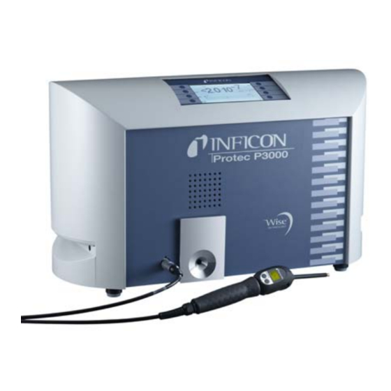
Page 19: Instrument Views Of The Protec P3000
Set up How to remove the transportation lock: The transportation lock is located on the bottom side of the Protec P3000 and consists of a yellow knurled screws. Please remove this screw before starting-up the leak detector. The Protec P3000 is supplied ready for operation. Initial start-up is described in Section 3.1. -
Page 20: Mechanical Connections
20 cm 8) (8 in.) must be kept unobstructed to the sides. The clearance at the rear must be no less than 10 cm (4 in.). Moreover, the Protec P3000 handles for carrying the leak detector at the sides of the main unit must not be covered at any time as these acts as air inlet and outlet. - Page 21 SL3000(XL) Sniffer line In order to operate the Protec P3000 it is essential for the SL3000(XL) sniffer line to be connected. The connection for the sniffer line is located at the front of the Protec P3000 left of the PRO-Check reference leak. Insert the plug into the opening with the red dot on the plug and the slot in the front cover aligned until the connector engages.
- Page 22 12-digit-code. Enter the serial number in the first line of the open submenu and the 12-digit-code in the second line and press OK. The PRO-Check reference leak must be installed in the Protec P3000 Notice when pressing Fig.
- Page 23 Fig. 7 Usage of sniffer line holder The installation is described in Fig. 8. There are two little slots on the front side at the very top area of the blue square front of the main unit. Hold the holder horizontally and then insert the two little hooks of the holder into the two slots (either on the right or the left side).
-
Page 24: Electrical Connections
1.6.4 RS232 Interface The Protec P3000 is equipped with a RS232 interface which is located on the rear right side of the main unit. This interface is of the DCE type (Data Communications Equipment) and allows the connection of a PC for monitoring and data logging. The connection is provided through a commercially available Sub-D plug. -
Page 25: I/O Port
PLC and analog data. For details see Section 6.1. Through this connection some functions of the Protec P3000 can be controlled exter- nally or measurement data or the status of the Protec P3000 may be communicated to external equipment. Through relay changeover contacts the trigger levels as well as the operating mode (Ready) of the Protec P3000 may be monitored. -
Page 26: How The Protec P3000 Works
2.2.1 Backing Pump A diaphragm pump in the Protec P3000 serves as the backing pump. All data and further information on this pump are given in the Operating Instructions. The backing pump generates the flow of the gas through the SL3000 sniffer line. -
Page 27: Valve Holder
All other subassemblies are controlled and monitored by this assembly. The microprocessor which is located here is thus continuously informed about the status of the entire Protec P3000 and can respond accordingly. In order to accept commands from the operator and to output measured values and messages, the control subassembly is linked to the display unit. -
Page 28: Sl3000(Xl) Sniffer Line With Probe Display
• The green LED will indicate that the Protec P3000 is in operation (switched on). The green LED will show continuous green light if an external display unit is connected and will blink if no external display unit is detected. - Page 29 ZERO. For details on the ZERO function see section 4.4.1) The right probe button is used for different functions depending on the current operating mode the Protec P3000 is set to: • in standard operation mode: –...
-
Page 30: Built-In Pro-Check Reference Leak
2.3.3 Built-in PRO-Check reference leak A built-in PRO-Check reference leak is available for all Protec P3000. The PRO- Check reference leak can be used for verifying the correct functioning of the Protec P3000 including the correct calibration and can also be used for re-calibrating the Protec P3000 if necessary. - Page 31 Pos. Description Pos. Description Connector at built-in test leak Connector at Protec P3000 housing The PRO-Check reference leak is not part of the Protec P3000 shipment Notice and needs to be ordered as a separate part no. (see section 1.3.2 Accessories).
-
Page 32: Operation Of The Protec P3000
The start-up procedure normally lasts 2 - 3 min. After extended times of Notice power off, however, the start-up of the Protec P3000 may take up to 20 min. max. To improve the start-up behaviour of the Protec P3000 after extended times ofpower off, see Section 3.8. -
Page 33: Controls On The Main Display Unit
The functions of the 8 control keys are displayed on the LC display. During measurements the main interface is the probe handle display giving all necessary information for proper leak testing. After start-up the Protec P3000 will automatically go into measurement mode. Fig. 18 Measurement screen Pos. - Page 34 CAL Button With the button on the upper right side of the display an external calibration of the Protec P3000 can be started at any time. For details on how to perform an external calibration see Section 3.5.3. Operation of the Protec P3000...
- Page 35 ZERO function see Section 4.4.1. List of gas parameters button Up to four different gas parameter sets can be stored in the Protec P3000. If more than one set of gas parameters are set-up, the list button on the right side of the display will appear in the menu screen.
-
Page 36: Controls On The Probe Display Unit
The right probe button is used for navigation when working in I•Guide mode (see Section 3.4.2) or for starting an internal calibration (see Section 3.5.2) Performing measurements The Protec P3000 offers two modes of operation: • The Standard Operation Mode (compatible to the Protec mode) •... -
Page 37: Standard Operation Mode
For operation in an environment where moisture (e.g. condensating water) may occur, a water-protection tip is available (Cat. no. 12246) which will protect the Protec P3000 against intake of liquids if necessary. For details on how to install the water potection tip see 1.6.2) - Page 38 4 cm/s (1.6 inch per second) along the welded seam. The distance between tip and test sample should be as small as possible. If a leak is detected the bar will grow. The Protec P3000 continuously compares the measured leak rates with the programmed trigger levels. If the trigger is exceeded the background colour of the probe display will change from green to red.
-
Page 39: I•Guide Operating Mode
In the I•Guide mode up to 10 pre-programmed testing procedures can be stored. If the number of locations to be tested is set to zero, the Protec P3000 will Notice operate in a continious mode without checking for a global leak rate but still issue the timer signal for proper testing. -
Page 40: Selecting An I•Guide Program
For Protec P3000XL only: If the Protec P3000XL is operated in mode, the gas type is displayed in HIGH FLOW inverted characters (on dark background) in the main display as well as on the sniffer probe display. Operation of the Protec P3000... - Page 41 For all Protec P3000 configurations In the I•Guide message line the Protec P3000 will prompt the user for action. First it will ask to move to the first testing position. Also on the probe display the message “okay pos. 1?” will be shown. Please confirm with the right probe button that the sniffer tip has reached the right location.
- Page 42 Result of I•Guide program: unit under test passed Pos. Description Pos. Description Program name Results of each location tested Gas type If the summarized global leak rate exceeds the global trigger the message “Global trigger exceeded!” will be displayed. Operation of the Protec P3000...
-
Page 43: The Info Page
The I•Guide mode can also be used as a timer signal only. If the number of Notice points is set to 0, the Protec P3000 will prompt for the next location to be tested continuously without using the global leak rate function. -
Page 44: Calibration And Self-Test
If a calibration is started during the first 20 minutes after power on, a Notice warning will be issued. Do not calibrate the Protec P3000 during the first 20 minutes after start-up. Also a verification of the calibration may lead to wrong results in the first 20 minutes after start-up. -
Page 45: Verifying A Calibration (Proof Function)
"sensitivity check OK" will be displayed. Fig. 32 Results of proof function for Protec P3000 If the value measured for the PRO-Check is out of range, the message "recalibration required!" will be displayed in inverted colors. -
Page 46: Internal Calibration
While holding the sniffer tip in the test leak opening, the Protec P3000 will measure the test leak. Afterwards the operator will be requested to remove the sniffer tip from the leak opening. -
Page 47: External Calibration
3.5.3 External calibration For external calibration it is recommended to use leak rates > 5x10 mbar l/s for Protec P3000 and leak rates of > 5x10 mbar l/s when calibrating the Protec P3000XL at (3000 sccm). HIGH FLOW If the reference leak rate is < 5x10... - Page 48 The old calibration factor as well as the new calibration factor will be displayed. If warnings are active and have been acknowledged during the calibration process, the message is endorsed with the information "with active warnings". Operation of the Protec P3000...
-
Page 49: Standby
Protec P3000. Nothing else is required. The parameters entered are saved by Protec P3000. After switching on, the Protec P3000 will revert to the same status it was in when it was switched off before. Storage for fast availability as back-up unit Due to accumulation of Helium (from air) in the sensor unit during storage the start- up time for the Protec P3000 will be approx. -
Page 50: Equipment Settings
Equipment Settings Menu Structure By pressing the menu button the main menu page opens. The following options will be displayed: Fig. 39 Main menu screen In the subsequent sub-menus the following frequently used functions will occur: The “up” and “down” keys allow scrolling through listed menu items. The currently selected menu item is highlighted by inverted colours. - Page 51 M ain m enu Standby/Start Library Gas Service User Gas Gas Trigger Gas 1 N am e (edit) H elium Gas 2 A dditio nal H e Gas 3 M o de Gas 4 T rigger&Unit D isplay lim it Search level Equivalent co rrectio n (H e) Settings...
-
Page 52: The Service Menu
Selecting gas equivalents and setting trigger values The Protec P3000 can detect leak rates as helium leak rates or in refrigerant equiva- lent leak rates. Up to four different sets of parameters can be stored by the Protec P3000. - Page 53 This submenu only is available when operating in gas equivalents. In this case the Protec P3000 may display the Helium leak rate in addition to the refrigerant equiva- lent leak rate in the main measurement screen. This feature may be selected or not selected.
- Page 54 Editing gas equivalent parameters Fig. 42 Selecting gases from the library Back in the edit gas submenu scroll to the line item and press HELIUM PERCENTAGE EDIT Fig. 43 Adjusting a refrigerant correction factor for gases from the gas library In the opening submenu the helium fill pressure, the fill pressure for the gas equiva- lent (refrigerant) later on and the concentration of helium used can be entered.
- Page 55 Fig. 44 Setting a refrigerant correction factor for a custom gas For a custom gas, the molecular mass, as well as the dynamic viscosity (in Pa ꞏ s) must be entered. Fig. 45 Editing parameters for refrigerant equivalent leak rates In the submenu you can now enter the value in the refrigerant equi-...
- Page 56 Fig. 46 Setting-up trigger level and unit of measurement Pos. Description Pos. Description Increasing the trigger value Changing the unit of measurement Decreasing the trigger value Changing the unit of measurement Display limit Fig. 47 Editing the lower display limit The lower display limit for each gas can be edited.
-
Page 57: Selecting A Set Of Gas Parameters
1.0 and 9.9 s. Default value: 5.0 s Contamination Limit The Protec P3000 offers a protection mode against high helium concentrations (contamination with helium). This feature should be used to prevent the sensor from accelerated aging when seeing large helium concentrations very frequently. The... - Page 58 HELIUM CONTAMINATED the sensor and it cannot be pumped away for clean up of the Protec P3000. Switching of the Protec P3000 while contaminated with large concentrations of helium will in fact lead to significantly increased start-up times afterwards.
- Page 59 Fig. 49 Changing the flow limits of the SL3000 sniffer line Flow settings (For Protec P3000XL only) The Protec P3000XL can be used in mode as well as in mode. LOW FLOW HIGH FLOW In the flow settings submenu all settings related to both flow modes can be adjusted. When entering the submenu four further submenus will be displayed: FLOW SETTINGS...
- Page 60 Flow limits HIGH FLOW Fig. 51 Variation of flow limits In this submenu the for the mode UPPER FLOW LIMIT LOWER FLOW LIMIT HIGH FLOW may be set-up. The can be set to values between 1500 and 2400 LOWER FLOW LIMIT sccm.
- Page 61 Flow mode (only available when SL3000XL sniffer line is connected) In this submenu the Protec P3000XL can be switched between mode and LOW FLOW mode. HIGH FLOW Default setting: Mode HIGH FLOW Limits low flow error This submenu is only available if the is set to ADDITIONAL LOW FLOW ERROR ENABLED...
- Page 62 Fig. 53 Setting-up a Menu-PIN for parameter protection If a new PIN is entered the Protec P3000 software will ask to repeat the new PIN to prevent entering errors. Afterwards the menu PIN will be changed to the new value.
-
Page 63: Audio Functions
Below the search level the loudspeaker will remain off. If the Protec P3000 is set to TRIGGER ALARM as the alarm type an additional button will be shown on the lower right side called TONE 1,2,3. -
Page 64: Display Settings
Shut off the Protec P3000 and switch it back on. During run-up press the third button from the top on both sides of the display simultaneously until the contrast is back to normal. - Page 65 Fig. 54 Setting-up the contrast of the main display Peak hold function can be enabled or disabled in this submenu. If the PEAK HOLD PEAK HOLD function is enable the maximum leak rate will be displayed for a preset time in addi- tion to the currently measured value in the main display.
-
Page 66: Setting-Up / Editing An I•Guide Program
4.4.4 Setting-up / editing an I•Guide Program When selecting the button a submenu page will open showing the SETUP PROGRAM list of 10 pre-programmable I•Guide programs and their current status (enabled / disabled). If a program is enabled it will be offered in the list of programs to select from when operating in the I•Guide mode. - Page 67 The I•Guide mode can also be used as a timer signal only. If the number of Notice points is set to 0, the Protec P3000 will prompt for the next location to be tested continuously without using the global leak rate function.
-
Page 68: Miscellaneous Settings
Date & Time In this submenu the internal clock of the Protec P3000 can be set. On the first page the date needs to be entered in the format DD.MM.YYYY. The lower right button () opens the second page on which the time in the format HH.MM is entered. -
Page 69: Interfaces
The software of the Protec P3000 will set the output voltage in such a manner that the trigger level itself will always be set within the second decade (i.e. within the range of 3 to 5 Volts). - Page 70 Converting an output voltage to a leak rate If the recorder outputs a certain voltage and you want to convert this to a leak rate, the following formula applies: – ------------ - (2 is used since one decade is spread over 2 Volts. 3 is used because the trigger level will always be within the range of 3 to 5 V).
-
Page 71: Rs232 Protocol
For details on this protocol please refer to the Interface Description (kins26e1). Default setting: ASCII Diagnostics protocol is a binary protocol used by INFICON for analysis in quality DIAGNOSTICS control and trouble shooting during manufacturing and service. Printer manual... -
Page 72: Select Plc Inputs
Format Date Time Gas equivalent Leak rate Unit Example 03.05.2005 12:31 6x10 mbar l/s When set to IꞏGuide mode the PRINTER MANUAL mode is without function. Printer auto the leak rate will be sent any time the set trigger level is exceeded. PRINTER AUTO At the time the signal drops below the trigger level the maximum detected leak rate will be sent. -
Page 73: Baud Rate & End Sign
PRO-Check In this submenu the PRO-Check reference leak can be disabled completely so that for Protec P3000 leak detectors without a PRO-Check onboard the leak detector does not check for the electrical connection with the reference leak anymore and no error message is issued. - Page 74 Press button If pressing the button the MEASURE BACKGROUND Protec P3000 will go into a special measurement mode and determine the background concentration of Helium currently prevalent in the environment. This process may take a couple of seconds. This feature is not a continuous signal display but should be used for trouble-shooting purposes only.
- Page 75 Menu item Format Description Sensor / Valve Warning Hex Code Adjust Error Hex Code Page 4: PRO-Check data Helium Gas type of internal leak Leak rate nom. / at T mbar l/s / mbar l/s Version / Checksum Hex Code Serial no.
- Page 76 Menu item Format Description Page 6: I/O Port data Here the current PIN assignment is displayed. The default configuration is shown in the picture. Page 7: Analog data AIN3 Sniffer length AIN4 +5V II Leak AIN5 +24V III ext AIN6 +5V I Sniffer AIN8 –15V MC50 AIN9 +15V MC50 AIN10 +24V MC50...
-
Page 77: History & Maintenance
& historical data that has been collected during the HISTORY MAINTENANCE operation of the Protec P3000 can be viewed as well as information about the maintenance status of the leak detector. View Error List In the all errors (and warnings) that have occurred during the operation ERROR LIST of the Protec P3000 are summarized. - Page 78 Fig. 59 Example of an Protec P3000 error list Calibration history In this listing all calibrations that were conducted during the operation of the Protec P3000 are collected. The when they were performed are stated, DATE TIME followed by the type of calibration (internal / external) and the calibration factor.
- Page 79 Protec P3000 had worked at the time when the maintenance task was performed and the type of maintenance that was conducted are listed. Details about each main- tenance task may be viewed when highlighting the appropriate line item and pressing button.
- Page 80 Fig. 63 Example of maintenance history list Confirm maintenance In this submenu the replacement of the main unit air filter can be confirmed and the date and the number of operation hours at which the maintenance task was performed is saved in the software. Maintenance of the diaphragm pump can only be confirmed in the Notice (password protected) service menu by trained personnell.
- Page 81 Fig. 65 Activating new PRO-Check gas reservoir PRO-Check Warntime Expire Date (See Section 7.7.5). Notice Equipment Settings...
-
Page 82: Protec P3000 Messages
Errors Errors are events which force an interruption of the measurements in progress and which the Protec P3000 is not capable of rectifying on its own. Errors are indicated in plain text together with an error number. The Protec P3000 remains in the error status. After the fault cause has been removed the error can be acknowledged by pressing the button. - Page 83 Wise Sensor not ignited Current from Wise Technology Restart the Protec P3000, if sensor too low for more than 10 problem persists, call nearest min after power on INFICON service representative!
- Page 84 P3000(XL)!!! value Supply fresh air through sniffer line quickly, restart the Protec P3000 and wait for Protec P3000 to recover! If problem persists, call nearest INFICON service repesentative! Flow has changed! Flow has changed by more...
- Page 85 Replace probe cable* Increase upper flow limit Upper flow limit setting too low See Section 4.4.1 Pump error Fore pump defective Call nearest INFICON service repesentative! Valve block error! Cannot recognize valve block Call nearest INFICON service version during self-test representative!
- Page 86 Replace sniffer line and recalibrate! Capillary blocked Or: Replace probe cable!* and recalibrate See Section Flow at calibration out of Only for Protec P3000 or limits! Protec P3000XL in LOW FLOW mode: Flow at calibration higher than upper flow limit or lower than...
- Page 87 HIGH FLOW HIGH FLOW mode) See section 4.4.1 Flow through sniffer below Only for Protec P3000 or error limit Protec P3000XL in LOW FLOW mode: Flow through sniffer line below limit low flow error for Replace sniffer tip filter and...
- Page 88 PRO-Check has been used for Please replace PRO-Check gas more than 1 year or has been reservoir! manufactured more than 2 See Section years ago. All EEPROM parameter of EEPROM in PRO-Check is Replace PRO-Check! PRO-Check lost! empty or faulty Protec P3000 Messages...
- Page 89 Repeat calibration, sniff test leak not long enough properly and for sufficient time Internal calibration not Not in measure mode when Wait until Protec P3000 enters possible calibration is attempted measurement mode! Not supported gas in PRO- Occurs only during internal...
- Page 90 Test leak value too high during Use smaller test leak for external external calibration! calibration! Calibration conditions not Sniffer removed during internal Repeat calibration acknowledge maintained calibration, internal calibration aborted * To be performed only by authorized INFICON service personnel. Protec P3000 Messages...
-
Page 91: Equipment Connections
Through this connection some functions of the Protec P3000 can be controlled exter- nally or measurement data or the of the Protec P3000 status may be communicated to external equipment. -
Page 92: Output
Pin 6 is a +24 V common output for supplying the PLC inputs and outputs, internally protected with fuse F4. 6.1.3 PLC Inputs These inputs can be used to control the Protec P3000 via a programmable logic control (PLC). Permissible maximum input voltage 28 V. Technical data 24V nominal input Low level: 0 …7 V... -
Page 93: Plc Outputs
6.1.4 PLC Outputs These outputs can be used to monitor the Protec P3000 via a programmable logic control (PLC). PLC Outputs are designed as an „Open Collector Output“ or a relay output. Please refer to the example given below for an open collector output „Error“. -
Page 94: Relay Outputs
Leak Error Ready Signal is LOW as long as the Protec P3000 is ready for measurements. Calibration stable Signal is LOW when the signal detected during a calibration had enough time to stabilize and goes back to HIGH after the background signal had enough time to... -
Page 95: Recorder Outputs
Leak Relay is Active (NO) if the preset trigger level is exceeded Ready Relay is Active (NO) as long as the Protec P3000 is ready for measurements. 6.1.4.2 Recorder Outputs Technical data Analogue output 0 … 10 V max. 1mA... -
Page 96: Rs232 Interface
CLEAR ERROR RS232 interface The RS232 interface can be used for external control of the Protec P3000 but also for simple export of data describing testing results. For how to set-up the RS232 interface please refer to Section 4.5. -
Page 97: Maintenance
Maintenance For all maintenance on the Protec P3000, the main power must be disconnected first. Maintenance schedule Required tools • 2 screw drivers, size 2 • 1 ring spanner wrench, 19 mm • 8 mm hexagonal screw driver (delivered with Protec P3000). -
Page 98: Exchanging The Air Filter
Before exchanging the filter the Protec P3000 must be disconnected from power. To exchange the air filter, place the Protec P3000 on its front-side or position it on the edge of a sturdy bench. If placing it on the edge of a bench, please pay attention to its center of gravity. - Page 99 Fig. 70 Dismounting of the air filter 1 Depending on the contamination the air filter should be cleaned or replaced as necessary. 2 Push in new (changed) air filter until fully in contact with dead stop. Fig. 71 Inserting the air filter 3 Close air filter fastener.
-
Page 100: Exchanging The External Fuses
The two fuses must be replaced by two fuses of the same rating. The required mains fuses are available as cat.-no. After having exchanged the fuse(s) firmly reclose the lid of the mains socket. Re-connect the mains cord to the Protec P3000 and switch on the leak detector. Fig. 72 Replacing the mains fuse Replacing filters in the sniffer line If the sniffer probe is clogged, a warning “Flow through capillary too low”... -
Page 101: Replacing The Felt Discs Of The Capillary Filter (For Sl3000 Only)
7.4.1 Replacing the felt discs of the capillary filter (for SL3000 only) The Protec P3000 must be recalibrated after any maintenance of the sniffer tip! 1 Switch of the Protec P3000 Fig. 73 screwing off capillary filter Fig. 74 pushing out felt filter 2 Unscrew capillary filter, push out old felt filter from the back side. -
Page 102: Replacing The Felt Discs When Using The Water Protection Tip (For Sl3000 Only)
The Protec P3000 must be set to mode for confirming Notice ADVANCED maintenance tasks. 8 Please recalibrate the Protec P3000 for most accurate display of leak rate. 7.4.2 Replacing the felt discs when using the water protection tip (for SL3000 only) 1 Switch off Protec P3000! 2 Screw off water protection tip! 3 Push out filter pads and metal grid from the back side. -
Page 103: Checking / Replacing The Sinter Filter (For Sl3000 Only)
For details see Chapter 4.7. 8 Please recalibrate the Protec P3000 for most accurate display of leak rate. 7.4.3... -
Page 104: Replacing The Filter Pad Of The Sniffer Tip (For Sl3000Xl Only)
10 Please recalibrate the Protec P3000 for most accurate display of leak rate. Replacing the filter pad of the sniffer tip (for SL3000XL only) - Page 105 Fig. 79 Removed filter pad 3 Place new filter pad in the cap nut and press it in carefully. The filter pad works in each direction. 4 Place new filter pad in the cap nut and press it in carefully. The filter pad works in each direction.
- Page 106 If still no W41 is issued, open again cap nut and check correct seating of filter pad. d Release thumb and reinstall plastic cap at end of sniffer tip. 7 Please recalibrate the Protec P3000 for most accurate display of leak rate. Maintenance...
-
Page 107: Switching The Capillary Filter (For Sl3000 Sniffer Line Only)
Switching the capillary filter (for SL3000 sniffer line only) At the top of the sniffer tip two different capillary filters can be mounted. Fig. 82 Pos. Description Pos. Description Taper Gasket (can be black or white) Plastic capillary filter Metal capillary filter 7.6.1 Switching from metal to plastic capillary filter When you switch from the metal capillary filter to the plastic capillary filter you need... -
Page 108: Switching From Plastic To Metal Capillary Filter
4 Reinsert the steel capillary and reinstall the sniffer tip. 5 Screw the plastic capillary filter onto the sniffer tip. 6 Please recalibrate the Protec P3000 for most accurate display of leak rate. 7.6.2 Switching from plastic to metal capillary filter... -
Page 109: Replacing The Gas Reservoir Of The Pro-Check
Replacing the gas reservoir of the PRO-Check Please take off the lid from the new gas reservoir 48 hours before Notice installation. Due to accumulation of gas in the membrane during storage, the leak rate will be higher than certified right after opening. Do not use the new gas reservoir for calibration during this time. - Page 110 Screw in the new reservoir with hex nut key only! Notice 4 Re-install the PRO-Check in the Protec P3000. The PRO-Check does not fit in the Protec P3000 completely. There is a Notice little gap between the front panel of the Protec P3000 and the PRO-Check.
- Page 111 ”. In the opening sub-menu enter the new serial number in the REPLACE HECK first line and the 12-digit-code in the second line and press okay. This submenu only is available if the Protec P3000 is set to ADVANCED Notice mode (see Section 4.4.1, User Mode)
- Page 112 Entering the new leak relevant codes is important as otherwise an accurate Notice calibration with the internal test leak and traceability of the calibration cannot be guaranteed. The empty container is not reusable and should be disposed according to Notice national law.
-
Page 113: Gas Library
Gas library The operating software of the Protec P3000 contains a list of about 100 gas equiva- lents which are relevant to the refrigerating industry. These gas equivalents are stored in a ROM (read only memory) and from the list contained in this memory gases and trigger levels may be selected through the corresponding sub-menus. - Page 114 Gas designation (max. Other Designations Molecular mass (amu) 5 digits) R125 R134a R141b R142b 100.5 R143a R152a 66.1 R170 30.1 Ethane R218 R227ea R236fa R245fa R290 44.1 Propane R356 166.1 R400 Blend of 50% R12 141.6 50% R114 R401A Blend of 53% R22 94.4 13% R152a...
- Page 115 Gas designation (max. Other Designations Molecular mass (amu) 5 digits) R402B Blend of 60% R22 94.7 38% R125 2% R290 R403A Blend of 75% R22 20% R218 5% R290 R403B Blend of 56% R22 103.3 39% R218 5% R290 R404A Blend of 44% R125 97.6...
- Page 116 Gas designation (max. Other Designations Molecular mass (amu) 5 digits) R407E Blend of 25% R32 83.8 15% R125 60% R134a R407F Blend of 40% R134a 82.1 30% R125 30% R32 R408A Blend of 7% R125 46% R143a 47% R22 R409A Blend of 60% R22 97.4...
- Page 117 Gas designation (max. Other Designations Molecular mass (amu) 5 digits) R413A Blend of 9% R218 88% R134a 3% R600 R414A Blend of 51% R22 28.5% R124 96.9 4% R600a 16.5% R142 R415A Blend of 82% R22 81.7 18% R152a R416A Blend of 59% R134a 111.9...
- Page 118 Gas designation (max. Other Designations Molecular mass (amu) 5 digits) R448A Blend of 26% R32 26% R125 99.3 21% R134a 20% R1234yf 7 % R1234ze R449A Blend of 25.7% R134a 25.3% R1234yf 87.2 24.7% R125 24.3% R32 R450A Blend of 58% R1234ze 42% R134a R452A...
- Page 119 Gas designation (max. Other Designations Molecular mass (amu) 5 digits) R506 Blend of 55% R31 93.7 45% R114 R507 Blend of 50% R125 98.9 50% R143a R508A Blend of 39% R23 100.1 61% R116 R508B Blend of 46% R23 95.4 54% R116 R513A Blend of...
- Page 120 Gas designation (max. Other Designations Molecular mass (amu) 5 digits) Hydrogen R718 Helium HT135 Galden HT135 Krypton Nitrogen Neon 20.2 R717 Oxygen 146.1 Xenon 131.3 ZT130 Galden ZT130 Gas library...
-
Page 121: Ce Declaration Of Conformity
CE Declaration of Conformity Fig. 91 CE Declaration of Conformity... - Page 122 CE Declaration of Conformity...
-
Page 123: Appendix
Appendix accessories global trigger air filter alarm history alarm delay ambient temperature audio volume I/O Port autozero I/O port I•Guide I•Guide mode background Info button basic menu info button installation calibrated leak interface calibration internal calibration calibration factor calibration history language capillary filter leak rate... - Page 124 self-test sinter filter sniffer sniffer light sniffer line sniffer probe sniffer tip sniffer tips Standby Delay transportation lock trigger verification warning weight zero zero button zero time Appendix...
- Page 125 Appendix...
Need help?
Do you have a question about the Protec P3000 and is the answer not in the manual?
Questions and answers
Every time I try to use the machine it give me error 37 and it’s not working
Error 37 (E37) on the Inficon Protec P3000 machine indicates that the flow through the sniffer is too high. This can occur if the actual flow exceeds the upper flow limits in LOW FLOW and HIGH FLOW modes or if the actual pressure is higher than the upper pressure limit in HIGH FLOW mode only. Possible causes include a broken or leaky capillary. The recommended actions are to replace the sniffer line and recalibrate or replace the probe cable. Additionally, increasing the upper flow limit may help resolve the issue.
This answer is automatically generated