SpectraLink DECT Server 2500 Installation Manual
Hide thumbs
Also See for DECT Server 2500:
- Manual (3 pages) ,
- Synchronization and deployment manual (36 pages) ,
- Interoperability manual (31 pages)
Table of Contents
Advertisement
Quick Links
Advertisement
Table of Contents

Related Manuals for SpectraLink DECT Server 2500


Summary of Contents for SpectraLink DECT Server 2500
- Page 1 Spectralink DECT Server 2500 Installation Guide 14205700 version 9.0 June, 2015...
- Page 2 The drawings and specifications contained herein are the property of Spectralink and shall be neither reproduced in whole or in part without the prior written approval of Spectralink, nor be implied to grant any license to make, use, or sell equipment manufactured in accordance herewith.
-
Page 3: Table Of Contents
Connecting the Spectralink DECT Server 2500 Cables ....... . . - Page 4 Spectralink DECT Server 2500 Installation Guide Appendix B: Cable Connections ... . . 29 Analogue Interface Card ............29 Base Station Interface Card .
-
Page 5: Spectralink Dect Server 2500 Installation
Installing the Spectralink DECT Server 2500 The Spectralink DECT Server 2500 can be installed on a flat surface or on a wall. Before you start the installation, place the Spectralink DECT Server 2500 on a stable flat surface in the selected location, and inspect the package for any damage and report it to the reseller or distributor immediately. -
Page 6: Spectralink Dect Server 2500 Components
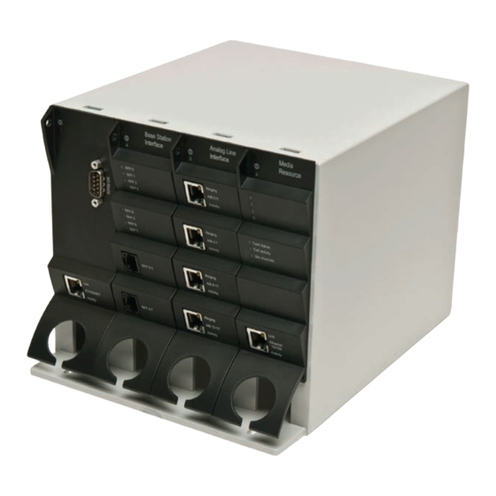
Operating altitude Up to 2000 m (6,500 ft) Operating ESD level 4 KV Spectralink DECT Server 2500 Components The following table contains all Spectralink DECT Server 2500 parts and their part numbers. Picture Description Part Numbers Base Station Interface 0233 9100... - Page 7 Spectralink DECT Server 2500 Installation Guide Picture Description Part Numbers Media Resource Card 0233 9700 Mains adaptor 8476 9904 - AV only EU mains cable 8468 7013 UK mains cable 8468 7014 US mains cable 8468 7015 RS232 cable 13281100 14205700 Version 9.0...
-
Page 8: Connections
Spectralink DECT Server 2500 Installation Guide Connections Figure 1 CPU Card Connections Link upwards RS232 Link downwards Ethernet Note Link connections must not be left open. You have to either plug in a link cable or a terminator connector for protection and for stable functionality. -
Page 9: General Installation Information
Keep the area around the Spectralink DECT Server 2500 clean and free of clutter. • Decide on a suitable surface that will hold the Spectralink DECT Server 2500 unit. It should be situated in a clean, dry, and dust-free area that is well ventilated. Avoid areas where heat, electrical noise, and electromagnetic fields are generated. -
Page 10: Installing The Spectralink Dect Server 2500 On A Wall
Leave at least 10 centimeter of free air above the unit for ventilation. Mount the Spectralink DECT Server 2500 securely using two screws. Use wall plugs, expansion bolts or other appropriate fastening methods in relation to the wall material. Remove any drilling dust. - Page 11 Spectralink DECT Server 2500 Installation Guide Figure 5 Wall mounting method 1 Mounting support on the inside 20 cm 20 cm Floor Figure 6 Wall mounting method 2 Mounting support on the inside 20 cm 20 cm Floor 14205700 Version 9.0...
-
Page 12: Connecting The Spectralink Dect Server 2500 Cables
20 cm Floor Connecting the Spectralink DECT Server 2500 Cables When the Spectralink DECT Server 2500 has been mounted, the cables can be connected. Cable Safety Precautions Before you connect the cables, ensure to take the following electrical safety precautions. -
Page 13: Installing Interface Cards And Cpu Cards
The Spectralink DECT Server 2500 has one power plug on the back panel. Plug a suitable power cord into the AC power adapter. Insert the AC power adapter output connector firmly into the socket on the Spectralink DECT Server 2500 so that the retention clip snaps to the plug. - Page 14 Cables. To Install CPU Cards Ensure that the Spectralink DECT Server 2500 is powered off completely. With two hands, gently slide the card into the unit. Give the card a gentle push on the last centimeter so that it enters the backplane connector properly.
- Page 15 Connect the power and reboot the unit. Connecting Interface Cables The front interface of the Spectralink DECT Server 2500 is provided with connectors for the different interfaces provided. Please see the Spectralink DECT Server 2500 Configuration Guide for the actual pin-out of the different connectors.
- Page 16 Spectralink DECT Server 2500 Installation Guide Figure 10 Harnessing cables to the back and out 14205700 Version 9.0 June, 2015...
- Page 17 Spectralink DECT Server 2500 Installation Guide Figure 11 Harnessing cables to the side and out. Regardless of which way is used for harnessing, you must guide the cables through the opening in the plastic front. This ensures safe retention of the cable.
-
Page 18: Replacing Components
Spectralink DECT Server 2500 Installation Guide Chapter 2: Replacing Components The Spectralink DECT Server 2500 is designed to minimize down-time. Several components can be replaced while the system is up. Component Replacement The following components are hot-swappable: • Interface cards •... - Page 19 The backplane cannot be replaced on-site. The Spectralink DECT Server 2500 will have to be returned for repair or be replaced with a new one. If a new Spectralink DECT Server 2500 is to be installed, you can move the cards from the faulty Spectralink DECT Server 2500 to the new one.
-
Page 20: Regulatory Notices
This equipment has a maximum operating ambient of 40°C. The ambient temperature in the rack shall not exceed this temperature CE Mark R&TTE Directive SPECTRALINK declares that the SPECTRALINK DECT Server 8000 is in conformity with the following relevant harmonized standards: EN 60950-1: 2006 + A11:2009 + A1:2010 + A12:20116100-3-261...
Need help?
Do you have a question about the DECT Server 2500 and is the answer not in the manual?
Questions and answers