Chapters
Table of Contents
Troubleshooting

Subscribe to Our Youtube Channel
Related Manuals for USC LPX300


Summary of Contents for USC LPX300
- Page 1 LPX SEED TREATER Operators Manual Software Release: USC - Manual - Treater v2.2 Document: TD-09-06-1035 Revision: E 2320 124th Road Sabetha, Kansas 66534 P: (785) 431-7900 F: (785) 431-7950 www.uscllc.com Revision Effective 26 JAN 2018...
- Page 2 OVERVIEW The purpose of this manual is to provide you with the basic information needed to operate and maintain the LPX Seed Treater. It does not hold USC, LLC liable for any accidents or injuries that may occur. The technical information provided in this document is based on extensive testing under controlled conditions at the USC research and development facility.
- Page 3 If there is any damage or shortages, the purchaser must immediately notify USC, LLC. Ownership passes to purchaser when the unit leaves the USC, LLC. premises. The purchaser is responsible for unloading and mounting all components of the equipment.
-
Page 4: Table Of Contents
Version 4 Automated Treater Connections ......25 Section C Mechanical Operation .............. 30 LPX Treater Overview ............30 LPX2000 Seed Wheel Overview ..........31 LPX300 Seed Wheel Overview ..........32 Atomizer Chamber Overview ..........33 Rotating Drum Overview ............34 Section D Electrical Operation ..............37 Startup Screen ................ - Page 5 LPX SEED TREATER Section Contents Page # Section G Maintenance ................62 Section H Storage ..................67 Section I Mechanical Drawings ............... 69 Section J Limited Warranty ..............147 Page 5...
-
Page 6: Section A
LPX SEED TREATER Section Safety Instructions Every year accidents in the work place maim, kill and injure people. Although it may be impossible to prevent all accidents, with the right combination of training, operating practices, safety devices, and operator vigilance, the number of accidents can be significantly reduced. - Page 7 LPX SEED TREATER Indicates an imminently hazardous situation which, if not avoided, will result in death or serious injury. Indique une situation extrêmement dangereuse qui, si pas ! DANGER évitée, entraînera la mort ou des blessures graves. Indicates a potentially hazardous situation which, if not avoided, could result in death or serious injury.
- Page 8 LPX SEED TREATER Mandatory Lockout Power Symbol. Disconnect, lockout and tagout electrical and other energy sources before inspecting, cleaning or performing maintenance on this panel. Symbole de puissance verrouillage obligatoire. Débranchez, de verrouillage et de déconsignation énergie électrique et d'autres sources avant d'inspecter, de nettoyage ou de la maintenance de ce panneau.
- Page 9 LPX SEED TREATER International Electrocution Hazard. This symbol indicates that an electrocution hazard exists. Serious injury or death could result from contacting high voltage. Danger d'électrocution international. Ce symbole indique qu'un danger d'électrocution existe. Des blessures graves ou la mort pourraient résulter de contact haute tension.
- Page 10 LPX SEED TREATER LOCKOUT / TAGOUT PROCEDURES Lockout/Tagout is the placement of a lock/tag on an energy isolating device in accordance with an established procedure. When taking equipment out of service to perform maintenance or repair work, always follow the lockout / tagout procedures as outlined in ANSI Z344.1 and/or OSHA Standard 1910.147.
- Page 11 LPX SEED TREATER CONTROLLED STOP This is the stopping of machine motion by reducing the electrical command signal to 0 (zero) once the stop signal has been recognized. ARRET CONTROLE Ce est l' arrêt du mouvement de la machine en réduisant le signal de commande électrique à...
- Page 12 LPX SEED TREATER YOU are responsible for the SAFE operation and maintenance of your USC, LLC equipment . YOU must ensure that you and anyone else who is going to operate, maintain or work around the equipment be familiar with the operating and maintenance procedures and related SAFETY information contained in this manual.
- Page 13 LPX SEED TREATER 4. Provide a fire extinguisher for use in case of an accident. Store in a highly visible place. 5. Do not allow children, spectators or bystanders within hazard area of machine. 6. Wear appropriate protective gear. This includes but is not limited ...
- Page 14 LPX SEED TREATER PLACEMENT SAFETY 1. Move only with the appropriate equipment 2. Stay away from overhead power lines when moving equipment. Electrocution can occur without direct contact. 3. Be familiar with machine hazard area. If anyone enters hazard areas, shut down machine immediately.
- Page 15 2. Replace safety labels that are missing or have become illegible. 3. Replaced parts that displayed a safety label should also display the current label. 4. Replacement safety labels are available. Contact USC at (785) 431-7900 . How to Install Safety Labels: ...
- Page 16 Think SAFETY! Work SAFELY! REMEMBER—If Safety Labels have been damaged, removed, become illegible, or parts replaced without safety labels, new labels must be applied. New safety labels are available from USC at (785) 431-7900. Part # 09-02-0001 Part # 09-02-0003...
- Page 17 LPX SEED TREATER Part # 09-02-0002 Page 17...
-
Page 18: C2D2 Specifications And Labels
LPX SEED TREATER C2D2 SPECIFICATIONS AND LABELS If any of the panels are located in the hazardous area described in the installation section (see page 19), the following criteria must be met. 1. All 120VAC connections must be hard wired to a listed IP65 rated enclosure in accordance with local electrical codes. -
Page 19: Section B
USC equipment may operate within a Group II, Division 2, Class G hazardous area which contains seed dust. If so, the equipment must be certified for use in this area. -
Page 20: Manual And Automated Treater Set-Up
également dans la zone dangereuse où se trouve le système USC. Si oui, nous recommandons que le pouvoir soit câblé dans la source. Ne pas utiliser une prise électrique standard à cet effet. Pour les autres méthodes acceptables de se connecter à... - Page 21 LPX SEED TREATER LPX MANUAL AND AUTOMATED TREATER SET - UP 4. Remove any boxes and cords from the drum of the treater. 5. Install the four provided legs and set up on a level surface, preferably concrete. When all four legs are mounted in the same pin hole, the seed treater has a slight slope to allow seed to travel through the machine.
-
Page 22: Version 3 Manual Treater Connections
LPX SEED TREATER VERSION 3 MANUAL TREATER ELECTRICAL CONNECTIONS 1. Ensure the two included red plugs are inserted into the PJESTOPA and PJESTOPB connectors. 2. Connect the communication cable from the pump stands PJ3009 to any of the four connectors PJ2602 – PJ2605 on the bottom of the main treater panel. 3. - Page 23 LPX SEED TREATER VERSION 3 MANUAL TREATER ELECTRICAL CONNECTIONS 8. Connect the PJ2010 atomizer motor cable to the atomizer motor. 9. Connect the treater inlet conveyor to the PJ2106F connector. 10. Connect the treater inlet conveyor to the PJ2110F connector. SEED WHEEL SMW HOPPER PROXIMITY SENSOR Page 23...
- Page 24 (right), or the electrical schematic shipped with the piece of equipment. This will power the USC LPX Manual seed treater and any attached conveyors.
- Page 25 LPX SEED TREATER VERSION 4 MAIN CONTROL PANEL CONNECTIONS 1. Attach the Main Control Panel to the control panel stand using the provided hardware. Determine the permanent location you will be operating the system from, then anchor the stand to the floor. The panel may also be mounted to a wall. 2.
- Page 26 LPX SEED TREATER VERSION 4 MAIN CONTROL PANEL CONNECTIONS 5 There are three USB ports located on the bottom of the panel that may be used to plug in a mouse, keyboard or download reports to a compact flash device. 6 There is also a connector (PJ1202) where the customer supplied internet connection is made.
-
Page 27: Version 4 Automated Treater Connections
LPX SEED TREATER VERSION 4 LPX AUTOMATED TREATER CONNECTIONS 7. If you have manual or semi-automated pump stands, connect the 2 pin communication cables from pump stands to one of the auxliary ports on the treater control panel. 8. Connect the cable from the drum motor to PJ2006 on the treater control panel. 9. - Page 28 LPX SEED TREATER VERSION 4 LPX AUTOMATED TREATER CONNECTIONS SMW HOPPER PROXIMITY SENSOR SEED WHEEL Page 28...
- Page 29 This will power the USC LPX seed treater and any attached conveyors.
-
Page 30: Section C
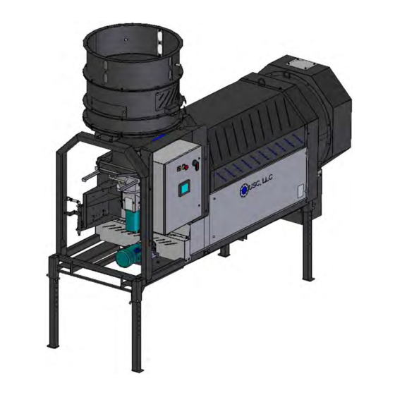
LPX SEED TREATER Section Mechanical Operation LPX TREATER OVERVIEW Proximity 12” Extension Ring Switch Rotating Drum Seed Wheel Adjustable Seed Flow Gate Quick Release Atomizer Chamber Handle Discharge Chute Plumbing Treater To Atomizer Control Panel Atomizer Motor Drum Motor Adjustable Legs Page 30... -
Page 31: Lpx2000 Seed Wheel Overview
LPX SEED TREATER LPX2000 SEED WHEEL The hopper is equipped with three proximity switches. The top switch controls the inlet conveyor and the lower switches, located in the seed wheel, control the pump(s). Refer to H-O-A Screen in section D. See the Proximity Switch Adjustment Guide in Section F for more in-depth information on these switches. -
Page 32: Lpx300 Seed Wheel Overview
LPX SEED TREATER LPX300 SEED WHEEL OVERVIEW The hopper is equipped with three proximity switches. The top switch controls the inlet conveyor and the lower switches, located in the seed wheel, control the pump(s). Refer to H-O-A Screen in section D and Section G: Troubleshooting; Proximity Switch Adjustment Guide for more in-depth information on these switches. -
Page 33: Atomizer Chamber Overview
LPX SEED TREATER ATOMIZER CHAMBER OVERVIEW The atomizer chamber consists of a patented design which disperses treatment evenly to each seed. A motor drives the atomizer head at approximately 1725 RPM’s. As treatment is being pumped into the atomizer chamber, it drops into the atomizer head. The centrifugal force of the spinning head forces the treatment to be sprayed out through a screen covering in all 360 degrees. -
Page 34: Rotating Drum Overview
LPX SEED TREATER ROTATING DRUM The rotating drum comes in options of 5, 6 and 8 feet and accepts treated seed through the opening on the hopper end. As seed passes through the length of the drum it is tumbled, producing accurate and uniform seed coating. The seed then exits the seed treater out the discharge end of the machine. - Page 35 LPX SEED TREATER ROTATING DRUM Drum Telescoping Fork Pockets Retaining Clip Adjustable Page 35...
- Page 36 LPX SEED TREATER TREATING SEED The Illustration below shows how seed passes through the atomizing chamber. The red represents treatment being dispensed to the seed as it passes through the chamber. After the seed passes through the atomizer, it goes into the drum where the coating process is completed.
-
Page 37: Section D
This section provides a general overview and description of the operator control panels for the LPX Seed Treater. USC recommends the use of a surge protection device with a minimum rating of 400 Joules for all automated main control NOTICE panels. - Page 38 LPX SEED TREATER General Panel Descriptions The LPX Treater Main Panel is an enclosure that is attached to the side of the treater and contains the electrical components required to actuate the seed treater. This includes the VFDs for the seed wheel and atomizer. Power for the treater is supplied here.
-
Page 39: Startup Screen
LPX MANUAL TREATER HMI TOUCH SCREENS The following pages explain the function of the touch screen controls for the USC - Manual - Treater Ver 2.2 program. For the LPX Automated Treater, see the appropriate U-Treat Automation manual. USC STARTUP SCREEN While the system is booting up, the touch screen will display a timer bar at the bottom of the Start Up Screen. -
Page 40: Main Screen
LPX SEED TREATER MAIN SCREEN 1. PRODUCT STATUS BOX: Displays the name of the active product at the top of the display, as well as the current RPM of the seed wheel, target flow rate and the calculated flow rate. The totalizer displays the amount of material used. Run time displays the amount of elapsed time since the current run was started and the calibration ratio for the product being used. - Page 41 LPX SEED TREATER MAIN SCREEN 6. RESET TIMER: Pressing this button will manually reset the Run Time display after a run is complete. 7. AUTO RESET: When this button is active it will automatically resets the timer and run time after each run is completed. If it is active, it will be green. 8.
-
Page 42: Product Screen
LPX SEED TREATER PRODUCT SCREEN 1. PRODUCT SELECTION : Pressing this button advances the operator to the Product Selection screen (bottom, left). Use the arrows to scroll through the list to find the product you wish to use. The system can store up to 10 different product entries. Each product type will have its own name and calibration ratio. -
Page 43: Product Editing Screen
LPX SEED TREATER PRODUCT EDITING SCREEN 1. PRODUCT NAME: When this button is pushed an alpha numeric keypad appears allowing the operator to change an existing product name. If an unused box was selected from the list, the name will be blank and the Calibration Ratio will be 1.0, allowing the operator to enter a new product into the system. -
Page 44: Calibration Calculator Screen
LPX SEED TREATER PRODUCT EDITING SCREEN 8. MEASURE BY: Pressing this button toggles between the SCU and CWT measurement options. 9. SAVE: Saves any changes to the chemical profile. 10. CALIBRATION FACTOR: This button displays the calibration ratio from the Calibration Calculator. -
Page 45: Pump Rate Calculator Screen
LPX SEED TREATER CALIBRATION CALCULATOR SCREEN 7. CALCULATED RATIO: This display indicates the amount the current calibration will be adjusted when the apply button is pressed. 8. CURRENT RATIO: This display indicates the current calibration. 9. DEFAULT: Pressing this button returns all values to the default setting of one. The actual weight will always be the amount weighed by the scale. -
Page 46: Overview Screen
LPX SEED TREATER OVERVIEW SCREEN 1. SEED WHEEL STATUS BOX: Displays the name of the active product at the top of the box, as well as the current RPM of the seed wheel, target flow rate and the calculated flow rate. The totalizer displays the amount of material used. Run time displays the amount of elapsed time since the current run was started and the calibration ratio for the product being used. - Page 47 LPX SEED TREATER H-O-A (HAND-OFF-AUTO) SCREEN The E-Stop Reset push button must be pressed after every power cycle. After the E-Stop button has been pressed to stop a run, the E-Stop button must be pulled out and the E-Stop RESET button NOTICE pressed.
- Page 48 LPX SEED TREATER H-O-A (HAND-OFF-AUTO) SCREEN 4. INLET CONVEYOR: This module controls the inlet conveyor motor. Pressing the START button will turn the conveyor motor on and the button will turn green. Pressing the STOP button will turn the conveyor motor off and the button will turn red. The round indicator displays the motor status.
-
Page 49: Utilities Screen
LPX SEED TREATER UTILITIES SCREEN 1. INLET CONVEYOR RESTART DELAY TIME(S): Pressing this button brings up a numeric keypad allowing the operator to adjust the delay time in one second increments. This will determine how long after the inlet hoppers proximity sensor detects seed and shuts down the inlet conveyor, to turn it back on. -
Page 50: Security Screen
The operator uses this input to obtain access to the Setpoints screen. When this button is pressed an alpha numeric keypad will appear. The password is USC and should only be made accessible to personnel qualified to operate the system. -
Page 51: Setpoints Screen
LPX SEED TREATER SETPOINTS SCREEN 1. CUP WEIGHT OPTION: Pressing this button activates the Cup Weight button on the Product Editing screen (see page 43). Entering a cup weight will make the system more accurate on the first run without a calibration. 2. -
Page 52: Section E
LPX SEED TREATER Section Calibration DETERMINING SEED CUP WEIGHT The following is a list of steps to use when calibrating the seed wheel. A seed calibration cup, funnel, stand, and scale are used to calibrate the seed wheel. 1. Set the empty seed calibration cup on the scale and zero out the weight of the cup. - Page 53 LPX SEED TREATER DETERMINING SEED CUP WEIGHT Figure 1 Figure 3 Figure 2 ADJUSTING THE LPX TREATER SEED FLOW GATE The following pictures illustrate how to open, close, and adjust the opening of the seed flow gate. When the black lever is pulled down, the seed gate is in the CLOSED position, and will not allow seed to flow through.
- Page 54 LPX SEED TREATER ADJUSTING THE LPX TREATER SEED FLOW GATE When the black lever is pushed up, the seed gate is in the OPEN position, and seed will flow through. Regulate the amount of seed flowing through the seed treater by using the spring-loaded coupler and moving it to a different notch.
-
Page 55: Flow Meter Calibration
LPX SEED TREATER FLOW METER CALIBRATION The following steps illustrate how to calibrate a flow meter on an LPX manual series seed treater. You will need a stopwatch for this calibration 1. Determine a desired flow rate EXAMPLE: The seed treatment slurry rate is 5 ounces per cwt. Seed Flow Rate = 10.8 cwt/min. - Page 56 LPX SEED TREATER FLOW METER CALIBRATION 7. Take the flow meter reading that was previously noted and divide it by the actual liquid application rate. This number will give you the calibration factor that the flow meter reading will need to be adjusted by. EXAMPLE: Flow meter reading = 54 Oz./min Actual liquid application rate = 55.16 Oz./min Calibration factor = 54 / 55.16 = 0.9790...
-
Page 57: Treating Seed
LPX SEED TREATER TREATING SEED 1. Prime the line going to the atomizer by turning the Atomizer switch to ON and turn the SEED TREATMENT valve to PROCESS. Next turn the pump direction switch to FORWARD and the Hand / Off / Auto switch to Hand. Liquid should begin pumping up to the atomizer. - Page 58 LPX SEED TREATER TREATING SEED 5. Turn the Seed Wheel to ON. The Seed Wheel will speed up to the dialed-in RPM. The pumps will also begin pumping liquid into the atomizer, this will start the seed treating process. You may notice the RPM will run at a lower RPM under the load of NOTICE seed.
-
Page 59: Section F
LPX SEED TREATER Section Troubleshooting Below is a table describing the most frequent mechanical problems and solutions with the USC LPX Seed Treater. For further assistance, contact USC at (785) 431-7900. Problem Possible Cause Solution Inlet Conveyor will not turn on. - Page 60 LPX SEED TREATER Problem Possible Cause Solution Pump is fluctuating. 1. Restriction in tubing 1. Flush tubing and check filter for any restrictions. 2. Filter is plugged or missing gasket. 2. Clean filter and check for gasket. Seed calibration is fluctuating. 1.
-
Page 61: Proximity Switch Adjustment Guide
LPX SEED TREATER PROXIMITY SWITCH ADJUSTMENT GUIDE The proximity switches mounted in the extension ring and the seed wheel detect when seed is present. The proximity switch located in the extension ring is used to automatically shut off the inlet conveyor when the surge hopper is full. This proximity switch is not present on tower systems. -
Page 62: Maintenance
La mauvaise performance ou un danger peut survenir. Do not use compressed air or water under pressure to clean any of the components of the USC equipment. Ne pas utiliser d'air comprimé ou de l'eau sous pression pour ! DANGER nettoyer l'un des composants de l'équipement USC. - Page 63 Record the cleaning on the company required documents. If operating in a CSA 22.1, Class II, Division 2, Group G hazardous area, USC recommends this step be performed on a daily basis.
- Page 64 LPX SEED TREATER ATOMIZER To access the inside of the atomizer housing, disconnect the motor power cable from the atomizer motor, push up on the quick release handle and slide out the atomizer. After completing maintenance, slide the atomizer back into the operating position, pull down quick release handle to lock it in place and reconnect the motor power cord.
- Page 65 Record the cleaning on the company required documents. If operating in a CSA 22.1, Class II, Division 2, Group G hazardous area, USC recommends this step be performed on a daily basis.
- Page 66 Record the cleaning on the company required documents. If operating in a CSA 22.1, Class II, Division 2, Group G hazardous area, USC recommends this step be performed on a daily basis.
-
Page 67: Section H
LPX SEED TREATER Section Storage When storing the LPX Seed Treater for long periods of time, the following procedure must be followed to reduce the chance of rust, corrosion and fatigue of the treater. You can also use these steps when storing the machine for the winter. A dust mask and protective rubber gloves shall be used when cleaning the machine. - Page 68 LPX SEED TREATER ATOMIZER CHAMBER 1. Remove and clean the atomizer housing. 2. Remove the atomizer head and stainless steel plumbing. The atomizer head can be disassembled (right), for easier cleaning. It is threaded together and can simply be unscrewed. 3.
-
Page 69: Section I
The following pages show the parts of the LPX Seed Treater. Please have the part number ready when ordering parts. Contents Page # Common to all Standard LPX Treaters ..............70 LPX300 Treaters Only ................... 98 LPX2000 Treaters Only ..................104 LPX300 Seed Wheel ....................114 LPX2000 Seed Wheel ..................121 Portable Treaters Only ..................131 Main Control Panels ....................143... - Page 70 LPX SEED TREATER ATOMIZER HEAD ASSEMBLY (04-02-0004) Item # Part # Description 05-11-0014 PLT ATMZR CAP 05-11-0015 ATOMIZER SPACER 05-11-0016 DRIVE SPUD, BOTTOM 06-06-0003 SET SCRW, CP,.375-16 18-8 SS .50 13-05-0032 PERFORATED SCREEN,STD. Page 70...
- Page 71 LPX SEED TREATER DRUM & ATOMIZER 1.5HP MOTOR KIT (03-20-0100) Item Item # Part # Description 01-01-0105 MTR .33HP 1725RPM 56C 3PH TENV 01-01-0106 MTR 1.5HP 1725RPM TEFC 3PH 05-10-0805 DISK ATOMIZER MOTOR 06-01-0016 BOLT .375-16 X 1.00 ZP GR5 06-04-0003 WSHR LOCK SPLT .375 ZP The following parts are in the motor kit but do not...
- Page 72 LPX SEED TREATER DRUM & ATOMIZER 3HP MOTOR KIT (03-20-0101) Item # Part # 01-01-0105 01-01-0166 06-01-0016 06-04-0003 Item # Part # Description 01-01-0105 MTR .33HP 1725RPM 56C 3PH TENV 01-01-0166 MTR 3HP 1740RPM 182TC TEFC 3PH 06-01-0016 BOLT .375-16 X 1.00 ZP GR5 06-04-0003 WSHR LOCK SPLT .375 ZP The following parts are in the motor kit but do not...
- Page 73 LPX SEED TREATER LPX END CHUTE (18-01-0072) Item # Part # Description 05-10-3400 PLT DSCHG TRTR 05-10-3886 SKIRT DSCHG TRTR LPX2000 06-01-0171 BOLT CRG .3125-18X.750 ZP SHORT NECK 06-03-0002 NUT NYL LOCK .313-18 ZP GR5 Item # Part # Title 101FB5 ADPT END CHUTE EXT LPX2000 05-10-3400...
- Page 74 LPX SEED TREATER END CHUTE DOOR ASSEMBLY (05-07-0198) Item # Part # Description 05-10-3919 PLT DSCHG CHUTE DOOR GALV W LOGO 06-01-0006 BOLT, .250-20 X .75 UNC ZP GRADE 5 06-02-0033 NUT 6-32 K-LOCK ZP 06-03-0001 NUT,LOCK, .250-20 ZP G5 NYLON INSERT 06-06-0032 SCRW MACH 6-32 X .500 PHLP RDHD ZP 06-09-0028...
- Page 75 Part # Description 05-07-0198 ASSY END CHUTE DOOR GALV 05-10-3800 PLT CTR DISCH CHUTE 1 06-01-0124 BOLT FLG .375-16 X .750 ZP GR5 09-01-0042 ATWL LBL USC, LLC 3" X 15" PRO-CUT 18-01-0057 WDMT END CHUTE LPX CS Page 75...
- Page 76 LPX SEED TREATER 4 PORT STATIC MIXER (04-03-0305) Page 76...
- Page 77 LPX SEED TREATER 4 PORT STATIC MIXER (04-03-0305) Item # Part # Description 02-02-0006 .500-14 NPT X 2-WAY VALVE 02-03-0005 HOSE RNT .500 CLEAR 6.81" LG 02-03-0005 STTC MIXER TO ATMZR HOSE 02-05-0005 FTTG CPLG .500 NPT FM SS 02-06-0010 FTTG 90 DEG .500HB X .500NPT ML NYL 02-06-0012 FTTG 90 DEG .500NPT FM SS...
- Page 78 LPX SEED TREATER 8 AND 12 PORT STATIC MIXER ADD ON KIT (04-03-0306) Page 78...
- Page 79 LPX SEED TREATER 8 AND 12 PORT STATIC MIXER ADD ON KIT (04-03-0306) Item # Part # Description 02-02-0006 .500-14 NPT X 2-WAY VALVE 02-03-0005 HOSE RNT .500 CLEAR 7" LG 02-06-0012 FTTG 90 DEG .500NPT FM SS 02-07-0007 FTTG NIP .500NPTX1.125 TBE SS CLOSE 02-08-0007 FTTG STGHT .500HB X .500NPT ML NYL 02-09-0003...
- Page 80 LPX SEED TREATER 16 AND 20 PORT STATIC MIXER ADD ON KIT (04-03-0307) Page 80...
- Page 81 LPX SEED TREATER 16 AND 20 PORT STATIC MIXER ADD ON KIT (04-03-0307) Item # Part # Description 02-02-0006 .500-14 NPT X 2-WAY VALVE 02-03-0005 HOSE RNT .500 CLEAR 7" LG 02-06-0012 FTTG 90 DEG .500NPT FM SS 02-07-0007 FTTG NIP .500NPTX1.125 TBE SS CLOSE 02-08-0007 FTTG STGHT .500HB X .500NPT ML NYL 02-09-0003...
- Page 82 LPX SEED TREATER LPX800 & LPX2000 6 FOOT DRUM ASSEMBLYS Page 82 Item # Part # Title 06-01-0003 BOLT, .250-20 X .750 UNC 18-8 SS 06-03-0014 NUT LOCK FLG .375-16 ZP GR5 06-04-0008 WSHR LOCK SPLT .375 SS 18-8...
- Page 83 LPX SEED TREATER LPX800 & LP2000 6 FOOT DRUM ASSEMBLYS LPX800 6FT CS LPX800 6FT SS LPX800 DRUM ASSEMBLY 18-01-0042 18-01-0043 Item # Description Part # Part # BOLT .250-20 X .75 UNC ——— — ——— — NUT FULL.375-16 SS 18-8 06-03-0014 06-02-0010 WASHER, LOCK, SPLIT .375 SS 18-8...
- Page 84 LPX SEED TREATER LPX2000 8 FOOT DRUM ASSEMBLY LPX2000 8FT CS LPX2000 8FT SS LPX DRUM ASSEMBLY 18-01-0046 18-01-0047 Item # Description Part # Part # BOLT .250-20 X .75 UNC 06-01-0006 06-01-0006 NUT FULL.375-16 SS 18-8 06-03-0014 06-02-0010 WASHER, LOCK, SPLIT .375 SS 18-8 ———...
- Page 85 LPX SEED TREATER SEED WHEEL SCALE KIT (13-04-0058) THIS MATERIAL IS THE CONF THIS MATERIAL IS THE CONF USC, LLC. USC, LLC. AND SHALL AND SHALL NAME NAME Material davidw davidw DRAWN DRAWN 07/25/2 07/25/2 CHECKED CHECKED Item # Part #...
- Page 86 LPX SEED TREATER LPX BASE FRAME ASSEMBLY (18-01-0011 & 18-01-0012) Page 86...
- Page 87 LPX SEED TREATER LPX BASE FRAME ASSEMBLY (18-01-0011 & 18-01-0012) Page 87...
- Page 88 LPX SEED TREATER LPX BASE FRAME ASSEMBLY (18-01-0011 & 18-01-0012) Page 88...
- Page 89 LPX SEED TREATER LPX BASE FRAME ASSEMBLY (18-01-0011 & 18-01-0012) LPX 6 FT LPX 8 FT LPX BASE FRAME ASSEMBLY 18-01-0011 18-01-0012 Item # Description Part # Part # GBOX IL 56C 16.2:1 GR B1 FOOT MNT 01-01-0101 01-01-0101 SPROCKET # 50 14T 1.00 IN BORE TYPE B 01-02-0093 01-02-0093 SPKT 17 T 50P .500 ID IDLER...
- Page 90 LPX SEED TREATER BASE TREATER ASSEMBLY DETAIL A Page 90...
- Page 91 LPX SEED TREATER BASE TREATER ASSEMBLY Page 91...
- Page 92 LPX SEED TREATER BASE TREATER ASSEMBLY Page 92...
- Page 93 LPX SEED TREATER BASE TREATER ASSEMBLY THIS MA THIS MA DRAWN DRAWN CHECKED CHECKED ENG APPR ENG APPR UNLESS OTH UNLESS OTH TOLERANCES: TOLERANCES: FRACTIONS FRACTIONS ± 1/16 ± 1/16 Page 93...
- Page 94 LPX SEED TREATER BASE TREATER ASSEMBLY Page 94...
- Page 95 LPX SEED TREATER BASE TREATER ASSEMBLY Page 95...
- Page 96 LPX SEED TREATER BASE TREATER ASSEMBLY (18-01-0446) TREATER 6 FOOT DRUM Item # Description Part # WHL GUIDE .375ID X 2.50 X .875 NPRN 01-06-0004 WDMT ADJ TREATER LEG 05-05-0001 TOP SHD CHAIN GRD GALV 05-06-0093 FRNT SHD, CHAIN GRD GALV 05-06-0094 GRD DRUM INLET LPX BOLTED 05-10-3931...
- Page 97 LPX SEED TREATER BASE TREATER ASSEMBLY (18-01-0447) TREATER 8 FOOT DRUM Item # Description Part # WHL GUIDE .375ID X 2.50 X .875 NPRN 01-06-0004 WDMT ADJ TREATER LEG 05-05-0001 TOP SHD CHAIN GRD GALV 05-06-0093 FRNT SHD, CHAIN GRD GALV 05-06-0094 GRD DRUM INLET LPX BOLTED 05-10-3931...
- Page 98 LPX SEED TREATER LPX300 SS ATOMIZER ASSEMBLY (18-01-0202) Page 98...
- Page 99 LPX SEED TREATER LPX300 SS ATOMIZER ASSEMBLY (18-01-0202) Item # Part # Description 01-03-0002 BRG FLG MNT .625ID 3.875 BASE 01-07-0027 CPLG CLPN .625 X .625 SPLT CS 02-06-0017 FTTG 90 DEG STRT .500NPT PPE BLK 02-15-0014 FTTG CPLG .500 NPT QCK DISC INSERT 04-02-0004 ASSY,ATOMIZER HEAD,4"...
- Page 100 LPX SEED TREATER LPX300 CS QD ADJUSTABLE CHAMBER ASSEMBLY (18-01-0356) Page 100...
- Page 101 LPX SEED TREATER LPX300 CS QD ADJUSTABLE CHAMBER ASSEMBLY (18-01-0356) SECTION A-A SECTION B-B Page 101...
- Page 102 LPX SEED TREATER LPX300 CS QD ADJUSTABLE CHAMBER ASSEMBLY (18-01-0356) DETAIL C 32 TYP 3 PLCS 16 TYP 2 PLCS DETAIL D Page 102...
- Page 103 LPX SEED TREATER LPX300 CS QD ADJUSTABLE CHAMBER ASSEMBLY (18-01-0356) Item # Part # Description 02-06-0008 FTTG 90 DEG .375NPT FM SS 02-07-0056 FTTG NIP .375 NPT X 9.00 304SS 02-15-0037 FTTG CPLG .375 NPT QCK DISC INSERT 03-08-0035 CONN CG BL NYL .750NPT .675-.750 RA...
- Page 104 LPX SEED TREATER LPX2000 SS QD ATOMIZER ASSEMBLY (18-01-0352) SECTION A-A Page 104...
- Page 105 LPX SEED TREATER LPX2000 SS QD ATOMIZER ASSEMBLY (18-01-0352) Page 105...
- Page 106 LPX SEED TREATER LPX2000 SS QD ATOMIZER ASSEMBLY (18-01-0352) Item # Part # Description 01-03-0002 BRG FLG MNT .625ID 3.875 BASE 01-07-0027 CPLG CLPN .625 X .625 SPLT CS 02-06-0007 FTTG 45 DEG .375NPT SS 02-06-0008 FTTG 90 DEG .375NPT FM SS 02-06-0017 FTTG 90 DEG STRT .500NPT PPE BLK 02-07-0002...
- Page 107 LPX SEED TREATER THIS PAGE INTENTIONALLY LEFT BLANK Page 107...
- Page 108 LPX SEED TREATER SMW CS FLOW CHAMBER ASSEMBLY (18-01-0350) SECTION A-A Page 108...
- Page 109 LPX SEED TREATER SMW CS FLOW CHAMBER ASSEMBLY (18-01-0350) Item # 05-03-0 05-10-2 06-01-0 06-01-0 06-02-0 06-03-0 06-04-0 SECTION B-B 06-06-0 06-12-0 06-12-0 06-12-0 Item # Part # Description 06-12-0 05-03-0336 WDMT,CHAMBER SUPPORT BRK SS 18-01-0 05-10-2062 BAR ECNTRC CONNECTING CS 06-01-0016 BOLT .375-16 X 1.00 ZP GR5 06-01-0081...
- Page 110 LPX SEED TREATER LPX2000 ADJUSTABLE CHAMBER ASSEMBLY (18-01-0062) SECTION A-A Page 110...
- Page 111 06-01-0116 SECTION B-B THIS MATERIAL IS THE CONFIDENTIAL AND PROPRIETAR THIS MATERIAL IS THE CONFIDENTIAL AND PROPRIETAR SECTION C-C USC, LLC. AND SHALL NOT BE USED WITHOUT PE USC, LLC. AND SHALL NOT BE USED WITHOUT PE NAME NAME DATE...
- Page 112 LPX SEED TREATER LPX2000 ADJUSTABLE CHAMBER ASSEMBLY (18-01-0062) DETAIL D SECTION E-E SECTION F-F Page 112...
- Page 113 LPX SEED TREATER LPX2000 ADJUSTABLE CHAMBER ASSEMBLY (18-01-0062) Item # Part # Description 05-03-0336 WDMT,CHAMBER SUPPORT BRK SS 05-04-0012 WDMT FLOW SLV ROD END TUBE 05-10-2062 BAR ECNTRC CONNECTING CS 05-11-0029 CPLG QCK CONNECT MACH 05-11-0030 BRKT FLOW CNTL CLEVIS 05-11-0034 ROD FLOW STOP ADJ 06-01-0016...
- Page 114 LPX SEED TREATER LPX300 SEED WHEEL ASSEMBLY (13-04-0226) Page 114...
- Page 115 A INITIAL DRAWING (See page 116) THIS MATERIAL IS THE CONFIDENTIAL AND PROPRIETARY THIS MATERIAL IS THE CONFIDENTIAL AND PROPRIETARY USC, LLC. AND SHALL NOT BE USED WITHOUT PER USC, LLC. AND SHALL NOT BE USED WITHOUT PER NAME NAME...
- Page 116 LPX SEED TREATER LPX300 SEED WHEEL ASSEMBLY (13-04-0226) DETAIL A Page 116...
- Page 117 LPX SEED TREATER LPX300 SEED WHEEL ASSEMBLY (13-04-0226) Page 117 THIS MATERIAL IS THE CONFIDENTIAL AND PROPRIETARY PROPERTY OF THIS MATERIAL IS THE CONFIDENTIAL AND PROPRIETARY PROPERTY OF...
- Page 118 LPX SEED TREATER LPX300 SEED WHEEL ASSEMBLY (13-04-0226) DETAIL C Page 118...
- Page 119 LPX SEED TREATER LPX300 SEED WHEEL ASSEMBLY (13-04-0226) Item # Part # Description 01-01-0229 GMTR RA .50 HP 11RPM 3PH HLLW SHAFT 01-10-0017 KEY 3/8 X 3.0 CS 03-06-0111 RECP TURCK RSF 44-1/M20/S717/S4000 03-08-0299 CONN CG 0.5NPT .170-.450 3232LTF 03-08-0308 NUT NYLOC .500 NPT 8464...
- Page 120 LPX SEED TREATER LPX300 SEED WHEEL ASSEMBLY (13-04-0226) Item # Part # Description 06-01-0204 BOLT FLG .375-16 X 2.50 ZP GR5 FTH 06-03-0013 NUT,LOCK, FLG .250-20 ZP SERRATTED 06-03-0014 NUT LOCK FLG .375-16 ZP GR5 06-03-0015 NUT LOCK FLG .500-13 ZP GR5 06-03-0019 NUT LOCK FLG .3125-18 ZP GR5...
- Page 121 LPX SEED TREATER LPX2000 SEED WHEEL ASSEMBLY (13-04-0201) Page 121...
- Page 122 LPX SEED TREATER LPX2000 SEED WHEEL ASSEMBLY (13-04-0201) A IN (See page 123) THIS MATERIAL IS THIS MATERIAL IS USC, LLC. AN USC, LLC. AN NAME NAME DRAWN DRAWN david david CHECKED CHECKED ENG APPR ENG APPR UNLESS OTHERWISE SPECIFIED...
- Page 123 LPX SEED TREATER LPX2000 SEED WHEEL ASSEMBLY (13-04-0201) DETAIL A Page 123...
- Page 124 LPX2000 SEED WHEEL ASSEMBLY (13-04-0201) Page 124 THIS MATERIAL IS THE CONFIDENTIAL AND PROPRIETARY PROPERTY OF THIS MATERIAL IS THE CONFIDENTIAL AND PROPRIETARY PROPERTY OF USC, LLC. AND SHALL NOT BE USED WITHOUT PERMISSION. USC, LLC. AND SHALL NOT BE USED WITHOUT PERMISSION.
- Page 125 LPX SEED TREATER LPX2000 SEED WHEEL ASSEMBLY (13-04-0201) DETAIL B Page 125...
- Page 126 LPX SEED TREATER LPX2000 SEED WHEEL ASSEMBLY (13-04-0201) Item # Part # Description 01-01-0229 GMTR RA .50 HP 11RPM 3PH HLLW SHAFT 01-10-0017 KEY 3/8 X 3.0 CS 03-06-0111 RECP TURCK RSF 44-1/M20/S717/S4000 03-08-0299 CONN CG 0.5NPT .170-.450 3232LTF 03-08-0308 NUT NYLOC .500 NPT 8464 03-08-0348 WSHR RDCG CNDT .75 X .5...
- Page 127 LPX SEED TREATER LPX2000 SEED WHEEL ASSEMBLY (13-04-0201) Item # Part # Description 06-01-0189 BOLT FLG .375-16 X 1.250 ZP GR5 06-01-0204 BOLT FLG .375-16 X 2.50 ZP GR5 FTH 06-03-0013 NUT,LOCK, FLG .250-20 ZP SERRATTED 06-03-0014 NUT LOCK FLG .375-16 ZP GR5 06-03-0015 NUT LOCK FLG .500-13 ZP GR5 06-03-0019...
- Page 128 LPX SEED TREATER SEED TREATER TOP ASSEMBLY Page 128...
- Page 129 LPX SEED TREATER LPX TREATER 6 FOOT 8 FOOT Item # Description Part # Part # MTR .33HP 1725RPM 56C 3PH TENV SEE TABLE 1 SEE TABLE 1 MTR 1.5HP 1725RPM TEFC 56C 3PH SEE TABLE 2 SEE TABLE 2 PANEL CONTROL LPV TREATER SEE TABLE 3 SEE TABLE 3...
- Page 130 LPX SEED TREATER SEED TREATER TOP ASSEMBLY TABLE 3 Part # Description 03-12-0462 PNL CNTL LPX TRTR AUTO 230V 1PH 1.5HP DRUM MTR (C2D2) 03-12-0464 PNL CNTL LPX TRTR AUTO 230V 3PH 1.5HP DRUM MTR (C2D2) 03-12-0466 PNL CNTL LPX TRTR AUTO 460V 3PH 1.5HP DRUM MTR (C2D2) 03-12-0468 PNL CNTL LPX TRTR AUTO 575V 3PH 1.5HP DRUM MTR (C2D2) 03-12-0470...
- Page 131 LPX SEED TREATER PORTABLE TREATER INLET HOPPER (13-04-0225) Item # Part # Description 03-08-0130 PLUG STEEL 22MM 05-07-0034 WDMT PORT EXT HOPP BOLT-ON 05-10-0362 PLT HOPP EXT VIEW 06-01-0006 BOLT .250-20 X .750 ZP GR5 06-01-0062 BOLT CRG .500-13 X 1.25 ZP GR5 06-02-0001 NUT FULL .250-20 ZP GR5 06-03-0004...
- Page 132 LPX SEED TREATER PORTABLE TREATER FRAME ASSEMBLY (18-01-0010) Page 132...
- Page 133 LPX SEED TREATER PORTABLE TREATER FRAME ASSEMBLY (18-01-0010) Page 133...
- Page 134 LPX SEED TREATER PORTABLE TREATER FRAME ASSEMBLY (18-01-0010) Page 134...
- Page 135 LPX SEED TREATER PORTABLE TREATER FRAME ASSEMBLY (18-01-0010) Item # Part # Description 01-01-0101 GBOX IL 56C 16.2:1 GR B1 FOOT MNT 01-02-0093 SPROCKET # 50 14T 1.00 IN BORE TYPE B 01-02-0095 SPKT 17T 50P .500 ID IDLER 01-03-0036 BRG PLW 1.00ID STSC SEALED 01-04-0005 CHAIN CTNG LINK 50P...
- Page 136 LPX SEED TREATER PORTABLE TREATER DRUM ASSEMBLY (18-01-0113) Page 136...
- Page 137 LPX SEED TREATER PORTABLE TREATER DRUM ASSEMBLY (18-01-0113) Item # Part # Description 06-01-0006 BOLT, .250-20 X .75 UNC ZP GRADE 5 06-03-0014 NUT LOCK FLG .375-16 ZP GR5 06-04-0001 WSHR LOCK SPLT .250 ZP 06-04-0013 WSHR SS BONDED SEALING .375 ID 06-10-0018 SEAL BRSH 180 DEG 7.81 OR X 4.00 IR 18-01-0024...
- Page 138 LPX SEED TREATER PORTABLE TREATER ASSEMBLY (18-01-0445) DETAIL A Page 138...
- Page 139 LPX SEED TREATER PORTABLE TREATER ASSEMBLY (18-01-0445) Page 139...
- Page 140 LPX SEED TREATER PORTABLE TREATER ASSEMBLY (18-01-0445) Page 140...
- Page 141 LPX SEED TREATER PORTABLE TREATER ASSEMBLY (18-01-0445) Page 141...
- Page 142 LPX SEED TREATER PORTABLE TREATER ASSEMBLY (18-01-0445) Item # Part # Description 01-06-0004 WHL GUIDE .375ID X 2.50 X .875 NPRN 05-06-0093 TOP SHD CHAIN GRD GALV 05-06-0094 FRNT SHD, CHAIN GRD GALV 05-10-3931 GRD DRUM INLET LPX BOLTED 05-10-3950 GRD DRUM BTM FRNT HALF LPX 6FT 05-10-3956 GRD DRUM BTM REAR HALF LPX PORT...
- Page 143 OTATION CAN BE ADJUSTED. LPX SEED TREATER ADJUSTABLE STAND STANDARD MAIN CONTROL PANEL ASSEMBLY (05-03-1471) Item # Part # Description 05-03-1479 WDMT PNL ADJ 05-03-1545 WDMT PANEL STAND ISOMETRIC VIEW 06-01-0153 BOLT CRG .375-16X.750 ZP SHORT NECK EXPLODED 06-01-0287 BOLT U .375-16 X 2.50 X 3.125 ZP 06-03-0014 NUT LOCK FLG .375-16 ZP GR5 06-10-0056...
- Page 144 LPX SEED TREATER VERSION 4 MAIN CONTROL PANEL ASSEMBLY (13-12-0159) Item # Part # Description 03-12-0529 CSA COMPLIANT MCP U-TREAT 05-03-1471 ASSY PNL FRM 4PUMP SAP 06-01-0124 BOLT FLG .375-16 X .750 ZP GR5 06-01-0220 BOLT 3/8-16 CONC ANCHOR ZP 3.75 06-03-0033 NUT LOCK FLG .375-16 GR8 Page 144...
- Page 145 LPX SEED TREATER VERSION 4 PORTABLE MAIN CONTROL PANEL ASSEMBLY (13-12-0158) Item # Part # Description 03-12-0529 CSA COMPLIANT MCP U-TREAT 05-03-1313 BIN SITE MAIN CNTL PNL FR 06-01-0020 BOLT .375-16 X 2.00 ZP GR5 06-01-0124 BOLT FLG .375-16 X .750 ZP GR5 06-03-0003 NUT NYL LOCK .375-16 ZP GR5 06-03-0014...
- Page 146 LPX SEED TREATER NOTES: Page 146...
- Page 147 Section USC Limited Warranty USC, LLC, (Manufacturer) warrants its seed treating equipment as follows: 1. Limited Warranty: Manufacturer warrants that the Products sold hereunder will be free from defects in material and workmanship for a period of 18 months from date of shipment.
- Page 148 LPX SEED TREATER USC, LLC 2320 124th road Sabetha, KS 66534 PHONE: (785) 431-7900 FAX: (785) 431-7950 EMAIL: sales-team@uscllc.com WEB: www.uscllc.com Page 148...
- Page 149 LPH800 SEED TREATER Operators Manual Document: TD-09-06-1033 Revision: B 2320 124th Road Sabetha, Kansas 66534 PH: (785) 431-7900 FAX: (785) 431-7950 www.uscllc.com Revision Effective 15 SEP 2016...
- Page 150 OVERVIEW The purpose of this manual is to provide you with the basic information needed to operate and maintain the LPH800 Seed Treater. It does not hold USC, LLC liable for any accidents or injuries that may occur. The technical information provided in this document is based on extensive testing under controlled conditions at the USC research and development facility.
- Page 151 If there is any damage or shortages, the purchaser must immediately notify USC, LLC. Ownership passes to purchaser when the unit leaves the USC, LLC. premises. The purchaser is responsible for unloading and mounting all components of the equipment.
- Page 152 LPH800 TREATER Table of Contents Section Contents Page # Legend ..................5 Section A Safety Instructions ..............6 Section B Installation ................13 Section C Mechanical Operation ............18 System Overview ..............18 Supply Hopper, Atomizer Chamber ........19 Rotating Drum ................ 20 Mix Tank, Calibration Tube ............
-
Page 153: Legend
LPH800 TREATER Legend Throughout this manual there are small icons located in the left margin. They indicate special information that may apply to your seed treater model. As the legend below indicates, there is 1 icon that represent a different seed treater setup. If you have a Cotton / Rice treater, please take note when one of these pictures is shown because it provides pertinent information. -
Page 154: Section A
LPH800 TREATER Section Safety Instructions Every year accidents in the work place maim, kill and injure people. Although it may be impossible to prevent all accidents, with the right combination of training, operating practices, safety devices and operator vigilance, the number of accidents can be significantly reduced. - Page 155 LPH800 TREATER Mandatory Lockout Power Symbol. Disconnect, lockout and tagout electrical and other energy sources before inspecting, cleaning or performing maintenance on this panel. International Safety Alert Symbol. The exclamation point (!) surrounded by a yellow triangle indicates that an injury hazard exists.
- Page 156 LPH800 TREATER LOCKOUT / TAGOUT PROCEDURES Lockout/Tagout is the placement of a lock/tag on an energy isolating device in accordance with an established procedure. When taking equipment out of service to perform maintenance or repair work, always follow the lockout/tagout procedures as outlined in ANSI Z344.1 and/or OSHA Standard 1910.147.
- Page 157 LPH800 TREATER YOU are responsible for the SAFE operation and maintenance of your USC, LLC equipment . YOU must ensure that you and anyone else who is going to operate, maintain or work around the equipment be familiar with the operating and maintenance procedures and related SAFETY information contained in this manual.
- Page 158 LPH800 TREATER 4. Provide a fire extinguisher for use in case of an accident. Store in a highly visible place. 5. Do not allow children, spectators or bystanders within hazard area of machine. 6. Wear appropriate protective gear. This includes but is not limited A hard hat ...
- Page 159 LPH800 TREATER PLACEMENT SAFETY 1. Move only with the appropriate equipment 2. Stay away from overhead power lines when moving equipment. Electrocution can occur without direct contact. 3. Be familiar with machine hazard area. If anyone enters hazard areas, shut down machine immediately.
- Page 160 2. Replace safety labels that are missing or have become illegible. 3. Replaced parts that displayed a safety label should also display the current label. 4. Replacement safety labels are available. Contact USC at (785) 431-7900 . How to Install Safety Labels: Be sure that the installation area is clean and dry.
-
Page 161: Section B
Discharge TREATER SET - UP The following steps outline the initial set-up of your USC Seed Treating system: 1. Clear the area of bystanders, especially small children, before moving. 2. Be sure there is enough clearance from overhead obstructions and power lines or other equipment to move the machine into its working position. - Page 162 LPH800 TREATER TREATER SET - UP 4. Remove any boxes and cords from the drum of the treater. 5. Install the four provided legs and set up on a level surface, preferably concrete. When all four legs are mounted in the same pin hole, the seed treater has a slight slope to allow seed to travel through the machine.
- Page 163 The USC system must be connected to the same electrical requirements as specified in the main control panel on the power requirement tag (right), or the electrical schematic shipped with the piece of equipment.
- Page 164 LPH800 TREATER LPH800 MIX TANK PLUMBING The following hoses must be connected from the Treater to the Mix Tank: 1. One hose from the supply valve on the bottom of the mix tank , to the top fitting on the SEED TREATMENT SOURCE valve located on the front of the treater. 2.
- Page 165 LPH800 TREATER LPH800 MIX TANK PLUMBING Page 17...
-
Page 166: Section C
LPH800 TREATER Section Mechanical Operation SYSTEM OVERVIEW Rotating 12” Extension Ring Drum Adjustable Seed Flow Gate Calibration Tube 30 - Gallon Mix Tank Discharge Chute Inoculant Atomizer Tank Chamber Pump #2 Inoculant Quick Tank Release Filter Atomizer Chamber Pump #1 Peristaltic Handle Pump 6-600 Motor &... - Page 167 LPH800 TREATER SUPPLY HOPPER The supply hopper has a capacity of approximately 7 units of seed. The hopper supplies seed to the atomizing chamber where seed first comes in contact with the treatment. The seed flow is controlled by an adjustable seed gate. Refer to the Calibration section page 30 for instructions on adjusting the seed flow gate.
-
Page 168: Rotating Drum
LPH800 TREATER ROTATING DRUM The rotating drum comes is six feet long and accepts treated seed through the opening on the hopper end. As seed passes through the length of the drum it is tumbled, producing accurate and uniform seed coating. The seed then exits the seed treater out the discharge end of the machine. - Page 169 LPH800 TREATER MIX TANK The LPH800 Treater includes a 30 gallon stainless steel chemical mix tank. This mix tank will have electric drive agitation that is turned on or off from a manual switch. The agitator should be running at all times when treatment is present in the mix tank to keep the chemical mixed and in a suspended state.
-
Page 170: Peristaltic Pump Heads And Motor
LPH800 TREATER PERISTALTIC PUMP HEADS AND MOTOR The LPH800 Treater utilizes a variable speed peristaltic pump and special norprene pump tubing for liquid metering. The pump comes equipped with a peristaltic pump head. Liquid will only come into contact with the inside diameter of the pump tubing and not the pump. - Page 171 LPH800 TREATER PUMP #1 LIQUID SYSTEM VALVES SEED TREATMENT SOURCE VALVE: This valve controls where pump #1 is drawing liquid from. Pump #1 Drawing from Pump #1 Drawing from bottom of Mix Tank bottom of Calibration Tube SEED TREATMENT: This valve controls the direction of the liquid coming from pump #1.
-
Page 172: Pump #2 Liquid System Valves
LPH800 TREATER PUMP #2 LIQUID SYSTEM VALVES INOCULNT VALVE: This valve controls the direction of the liquid coming from the tank. Pump #2 Pumping Liquid to Pump #2 Pumping Liquid to the Calibration Valve Atomizer CALIBRATION VALVE: This valve directs liquid which comes from the calibrate side of the Inoculant valve. - Page 173 LPH800 TREATER Proper calibration of the liquid system is critical to achieve a proper granular/chemical mixture. Use the calibration procedures on pages 32 through 35 to determine liquid flow rate. Emptying the remaining liquid can be done by using the reverse function on the control panel.
-
Page 174: Section D
LPH800 TREATER Section Electrical Operation HIGH VOLTAGE ~ Always disconnect the power source before working on or near the control panel or lead wires. HIGH VOLTAGE ~ Use insulated tools when making adjustments while the controls are under power. AUTHORIZED PERSONNEL only shall work on the control panel. - Page 175 LPH800 TREATER CONTROL DESCRIPTIONS 1. PUMP #1 VOLTMETER: Displays the DC voltage for pump #1. As pump #1 speed is increased or decreased, this number will also increase or decrease. 2. HAND / OFF / AUTO SWITCH (for Pump #1 & #2): This switch controls pump #1, pump #2, and any device connected to the auxiliary port.
- Page 176 LPH800 TREATER CONTROL DESCRIPTIONS 8. INLET CONVEYOR SWITCH: This switch controls the inlet conveyor in conjunction with a timer relay. When the switch is turned on, the conveyor will run until seed covers the proximity switch mounted near the top of the supply hopper, at which time the conveyor will turn off automatically.
- Page 177 LPH800 TREATER Bottom of Control Panel 1. ATOMIZER MOTOR CABLE: The other end of this cable plugs into the receptacle on the atomizer motor. The atomizer cable may be disconnected from the atomizer so it can be removed from the machine for maintenance. 2.
-
Page 178: Section E
Calibration of both the seed flow and liquid portions of the equipment is necessary for accurate treatment of seed. If you require metric data there are two options. Contact USC customer service for a copy of the Red Lion Cub 5 Programming... -
Page 179: Adjusting The Seed Flow Gate
LPH800 TREATER ADJUSTING THE SEED FLOW GATE Below are pictures that illustrate how to open, close, and adjust the opening of the seed flow gate. When the black lever is pulled down, the seed gate is in the closed position, and will not allow seed to flow through When the black lever is pushed up, the seed gate is in the open... -
Page 180: Pump #1 Calibration
LPH800 TREATER PUMP #1 CALIBRATION The following steps illustrate how to calibrate pump #1 on an LPH800 seed treater. A stop watch will be needed in the calibration process. If the seed treater is equipped with a flow meter, refer to the Flow NOTICE Meter operator’s manual for pump calibration instructions. - Page 181 LPH800 TREATER PUMP #1 CALIBRATION 9. Using the stop watch, determine the pump flow rate. Keeping the pump running, position the valve on top of mix tank to CALIBRATION TUBE. When liquid reaches 0 (zero) or an even number, begin timing for one minute. (see Figure 1, below) 10.
-
Page 182: Pump #2 Calibration
LPH800 TREATER PUMP #2 CALIBRATION The following steps illustrate how to calibrate pump #2 on an LP series seed treater. A stop watch and measuring cup will be needed in the calibration process. 1. Lock down the pump tubing in the Pump #2 pump head. (page 22) 2. - Page 183 LPH800 TREATER PUMP #2 CALIBRATION 11. As soon as one minute is up, position the Calibration Valve back to RECIRCULATE. Read the level on the side of the measuring cup. This number should equal the number of ounces needed to flow through the pump in one minute.
- Page 184 LPH800 TREATER Standard Data Below are two charts that show the potential volts and oz / min of two different pumps at different dial settings. All calibrations were done using water. Numbers are not exact, NOTICE only use these numbers as a starting point or for troubleshooting.
- Page 185 LPH800 TREATER Metric Data Below are two charts that show the potential volts and ml / min of two different pumps at different dial settings. All calibrations were done using water. Numbers are not exact, NOTICE only use these numbers as a starting point or for troubleshooting.
-
Page 186: Treating Seed
LPH800 TREATER TREATING SEED 1. Prime the line going to the atomizer by turning the Atomizer switch to ON and turn the SEED TREATMENT valve to PROCESS. Next turn the pump direction switch to FORWARD and the Hand / OFF / AUTO switch to Hand. Liquid should begin pumping up to the atomizer. - Page 187 LPH800 TREATER TREATING SEED The Illustration below shows how seed passes through the atomizing chamber. The red represents treatment being dispensed to the seed as it passes through the chamber. After the seed passes through the atomizer, it goes into the drum where the coating process is completed.
-
Page 188: Section F
LPH800 TREATER Section Troubleshooting Below is a table describing the most frequent problems and solutions with the LPH800 Seed Treater. For further assistance, contact USC at (785) 431-7900. Problem Possible Cause Solution Inlet Conveyor will not turn on. 1. Inlet Conveyor proximity 1. - Page 189 LPH800 TREATER Problem Possible Cause Solution Pump is Fluctuating 1. Restriction in tubing. 1. Flush tubing and check filter for any restrictions. 2. Tubing was not broken-in properly before calibrating. 2. Allow pump to recirculate for 15 minutes before checking 3.
-
Page 190: Proximity Switch Adjustment Guide
LPH800 TREATER PROXIMITY SWITCH ADJUSTMENT GUIDE The proximity switches mounted in the extension ring and the seed wheel detect when seed is present. The proximity switch located in the extension ring is used to automatically shut off the inlet conveyor when the surge hopper is full. This proximity switch is not present on tower systems. -
Page 191: Section G
LPH800 TREATER Section Maintenance Proper maintenance of the LPH800 Seed Treater is critical for peak performance, reliability and accuracy of this system. The following is a guideline for the type of maintenance and servicing that should be performed on this unit. Your environment and uses may require additional maintenance and service beyond this list to assure a reliable and safe unit. - Page 192 LPH800 TREATER ATOMIZER To access inside of atomizer housing, push up on the quick release handle and slide back the atomizer (below). Quick-Release Handle Atomizer Head Slide back atomizer housing and grease bearing inside. Bearing needs just one pump of grease every 40 hours of use (right).
- Page 193 LPH800 TREATER MIX TANK Check motor. Check for any play in the mix tank shaft. Check valves, fittings, and plug on bottom of tank for leaks. Check chemical line tubing for abnormal wear. ELECTRICAL PANEL Check and tighten wire connections. ...
-
Page 194: Section H
LPH800 TREATER Section Storage When storing the LPH800 series seed treater for long periods of time, the following procedure must be followed to reduce the chance of rust, corrosion and fatigue of the treater. You can also use these steps when storing the machine for the winter. A dust mask and protective rubber gloves shall be used when cleaning the machine. - Page 195 LPH800 TREATER ROTATING DRUM 1. Remove the shields and clean out any seed that may have fallen underneath the drum. 2. Lubricate the chain to keep from corroding in storage. LIQUID SYSTEM 1. Make certain the inside of the tank is completely drained of chemical residue and thoroughly flush the inside of the tank with clean water.
-
Page 196: Section I
THIS MATERIAL IS THE CONFIDENTIAL AND PROPRIETARY PROPERTY OF THIS MATERIAL IS THE CONFIDENTIAL AND PROPRIETARY PROPERTY OF USC, LLC. AND SHALL NOT BE USED WITHOUT PERMISSION. USC, LLC. AND SHALL NOT BE USED WITHOUT PERMISSION. U S C ,... - Page 197 LPH800 TREATER LPH800 BASE FRAME ASSEMBLY (18-01-0011) Page 49...
- Page 198 LPH800 TREATER LPH800 BASE FRAME ASSEMBLY (18-01-0011) Page 50...
- Page 199 LPH800 TREATER LPH800 BASE FRAME ASSEMBLY (18-01-0011) Item # Part # Description 01-01-0101 GBOX IL 56C 16.2:1 GR B1 FOOT MNT 01-02-0093 SPROCKET # 50 14T 1.00 IN BORE TYPE B 01-02-0095 SPKT 17 T 50P .500 ID IDLER 01-03-0036 BRG PLW 1.00ID STSC SEALED 01-04-0005 #50 CNTG LINK...
- Page 200 LPH800 TREATER LPH800 ATOMIZER ASSEMBLY (18-01-0279) Page 52...
- Page 201 LPH800 TREATER LPH800 ATOMIZER ASSEMBLY (18-01-0279) Item # Part # Description 01-03-0002 BRG FLG MNT .625ID 3.875 BASE 01-07-0027 CPLG CLPN .625 X .625 SPLT CS 02-06-0007 ELBOW, .375-18 NPT, 45 DEG. SS 02-06-0008 FTTG 90 DEG .375NPT FM SS 02-06-0010 FTTG 90 DEG .500HB X .500NPT ML NYL 02-07-0001...
- Page 202 LPH800 TREATER LPH800 INOCULANT KIT ASSEMBLY (13-04-0088) Page 54...
- Page 203 LPH800 TREATER LPH800 INOCULANT KIT ASSEMBLY (13-04-0088) Item # Part # Description 01-01-0010 MTR .1HP 6-600RPM 90VDC 02-01-0005 PUMP HEAD PRST MF LS 115V 600RPM 02-03-0005 .5 RNT TUBING 20" LG 02-05-0027 FTTG CPLG .500 HB X .375 HB NYL 02-06-0010 FTTG 90 DEG .500HB X .500NPT ML NYL 06-01-0010...
- Page 204 LPH800 TREATER LPH800 DRUM ASSEMBLY (18-01-0042) Item # Part # Description 06-03-0014 NUT LOCK FLG .375-16 ZP GR5 06-04-0013 WSHR SS BONDED SEALING .375 ID 18-01-0016 WDMT DRUM LPX800 6FT CS 18-01-0026 WDMT DRUM PDL TALL 6FT CS 18-01-0034 WDMT DRUM PDL SHORT 6FT CS Page 56...
- Page 205 LPH800 TREATER LPH800 TREATER ASSEMBLY (Drum) DETAIL A Page 57...
- Page 206 LPH800 TREATER LPH800 TREATER ASSEMBLY (Drum and Drive Guards) Page 58...
- Page 207 LPH800 TREATER LPH800 TREATER ASSEMBLY (Inlet and Atomizer Chamber) Page 59...
- Page 208 LPH800 TREATER LPH800 TREATER ASSEMBLY (Discharge End) Page 60...
- Page 209 LPH800 TREATER LPH800 TREATER ASSEMBLY (Forklift Pockets and Bottom Guards) Page 61...
- Page 210 LPH800 TREATER LPH800 TREATER ASSEMBLY (Control Panel and Liquid System) (See page 72) Page 62...
- Page 211 INITIAL DRAWING 3/3/14 THIS MATERIAL IS THE CONFIDENTIAL AND PROPRIETARY PROPERTY OF THIS MATERIAL IS THE CONFIDENTIAL AND PROPRIETARY PROPERTY OF USC, LLC. AND SHALL NOT BE USED WITHOUT PERMISSION. USC, LLC. AND SHALL NOT BE USED WITHOUT PERMISSION. NAME NAME...
- Page 212 LPH800 TREATER LPH800 TREATER ASSEMBLY Item # Part # Description 01-01-0010 MTR .1HP 6-600RPM 90VDC 01-01-0100 MTR 1.5HP 1725RPM TEFC 56C 1PH 01-01-0104 MTR .33HP 1725RPM 56C 1PH TENV 01-06-0004 WHL GUIDE .375ID X 2.50 X .875 NPRN 02-01-0005 PUMP HEAD PRST MF LS 115V 600RPM 03-10-0051 SENS PROX 24-240 AC AB 875CPG8N18A2 04-03-0199...
- Page 213 LPH800 TREATER LPH800 TREATER ASSEMBLY Item # Part # Description 10373B PUMP MNT CLAMP 104D62 PUMP MNT CLAMP BACK 13-04-0043 ASSY EXT HOPP LP800-2000 12IN 13-04-0088 KIT INOC LP800 2010-2011 13-04-0208 ASSY CALB TUBE LPH 13-05-0039 KIT VLV ST SOURCE 13-05-0040 KIT VLV ST PROCESS 18-01-0011...
- Page 214 LPH800 TREATER 30 GALLON STAINLESS STEEL TANK ASSEMBLY (04-03-0204) Page 66...
- Page 215 LPH800 TREATER 30 GALLON STAINLESS STEEL TANK ASSEMBLY (04-03-0204) Item # Part # Description 01-01-0039 GBOX IL 61.8:1 56C OTP 56C INP 01-01-0104 MTR .33HP 1725RPM 56C 1PH TENV 01-07-0015 CPLG CLPN .625 X .750 X 1.50OD SS 02-02-0006 .500-14 NPT X 2-WAY VALVE 02-03-0005 DRAIN HOSE PUMP STAND 02-05-0028...
- Page 216 LPH800 TREATER 30 GALLON TANK AND BASE ASSEMBLY (04-03-0199) Page 68...
- Page 217 LPH800 TREATER 30 GALLON TANK AND BASE ASSEMBLY (04-03-0199) Item # Part # Description 02-02-0007 VLV BALL .500 NPT 3WAY BRSS 02-06-0017 1/2-14 NPT,SL 90 DEG. BP 02-07-0009 FTTG NIP .500 NPT X 1.75 TBE BLK 02-08-0007 FTTG STGHT .500HB X .500NPT ML NYL 02-14-0002 1/2-14 NPT,PLUG BP 04-03-0204...
- Page 218 LPH800 TREATER LPH CALIBRATION TUBE ASSEMBLY (13-04-0208) Page 70...
- Page 219 LPH800 TREATER LPH CALIBRATION TUBE ASSEMBLY (13-04-0208) Item # Part # Description 02-03-0005 TUBE,CALIBRATION TUBE INSIDE 02-06-0010 FTTG 90 DEG .500HB X .500NPT ML NYL 02-06-0011 FTTG 90 DEG .500HB X .750NPT ML NYL 02-08-0007 FTTG STGHT .500HB X .500NPT ML NYL 05-08-0006 WDMT,INOC.BRK,SM 05-08-0007...
- Page 220 LPH800 TREATER SOURCE VALVE & FILTER ASSEMBLY (13-05-0039) Item # Item # Part # Description 02-02-0007 .500-14 NPT 3-WAY VALVE 02-06-0010 FTTG 90 DEG .500HB X .500NPT ML NYL 02-07-0009 FTTG NIP .500 NPT X 1.75 TBE BP 02-12-0002 FLTR TEE PPE .500 NPT 16 MESH LRG 06-06-0008 SCRW MACH 10-24 X .250 PHLP PHD ZP 06-07-0006...
- Page 221 An electrical wiring diagram is located in the control panel of the seed treater at the time of shipment. The diagram located in the panel shows the exact electrical schematic for that model of seed treater. If you have any questions about the diagram, contact USC at (785) 431-7900. Item # Part #...
- Page 222 LPH800 TREATER NOTES: Page 74...
-
Page 223: Section J
Section USC Limited Warranty USC, LLC, (Manufacturer) warrants its seed treating equipment as follows: 1. Limited Warranty: Manufacturer warrants that the Products sold hereunder will be free from defects in material and workmanship for a period of 18 months from date of shipment. - Page 224 LPH800 TREATER USC, LLC 2320 124th road Sabetha, Ks 66534 PHONE: (785) 431-7900 FAX: (785) 431-7950 EMAIL: sales-team@uscllc.com WEB: www.uscllc.com Page 76...
Need help?
Do you have a question about the LPX300 and is the answer not in the manual?
Questions and answers