
Subscribe to Our Youtube Channel
Related Manuals for USC LPH800


Summary of Contents for USC LPH800
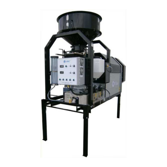
- Page 1 LPH800 SEED TREATER Operators Manual Document: TD-09-06-1033 Revision: B 2320 124th Road Sabetha, Kansas 66534 PH: (785) 431-7900 FAX: (785) 431-7950 www.uscllc.com Revision Effective 29 JULY 2015...
- Page 2 OVERVIEW The purpose of this manual is to provide you with the basic information needed to operate and maintain the LPH800 Seed Treater . It does not hold USC, LLC liable for any accidents or injuries that may occur. OPERATOR RESPONSIBILITIES...
- Page 3 If there is any damage or shortages, the purchaser must immediately notify USC, LLC. Ownership passes to purchaser when the unit leaves the USC, LLC. premises. The purchaser is responsible for unloading and mounting all components of the equipment.
-
Page 4: Table Of Contents
LPH800 TREATER Table of Contents Section Contents Page # Legend ..................5 Section A Safety Instructions ..............6 Section B Installation ................13 Section C Mechanical Operation ............18 System Overview ..............18 Supply Hopper, Atomizer Chamber ........19 Rotating Drum ................ 20 Mix Tank, Calibration Tube ............ -
Page 5: Legend
LPH800 TREATER Legend Throughout this manual there are small icons located in the left margin. They indicate special information that may apply to your seed treater model. As the legend below indicates, there is 1 icon that represent a different seed treater setup. If you have a Cotton / Rice treater, please take note when one of these pictures is shown because it provides pertinent information. -
Page 6: Section A
LPH800 TREATER Section Safety Instructions Every year accidents in the work place maim, kill and injure people. Although it may be impossible to prevent all accidents, with the right combination of training, operating practices, safety devices and operator vigilance, the number of accidents can be significantly reduced. - Page 7 LPH800 TREATER Mandatory Lockout Power Symbol. Disconnect, lockout and tagout electrical and other energy sources before inspecting, cleaning or performing maintenance on this panel. International Safety Alert Symbol. The exclamation point (!) surrounded by a yellow triangle indicates that an injury hazard exists.
- Page 8 LPH800 TREATER LOCKOUT / TAGOUT PROCEDURES Lockout/Tagout is the placement of a lock/tag on an energy isolating device in accordance with an established procedure. When taking equipment out of service to perform maintenance or repair work, always follow the lockout/tagout procedures as outlined in ANSI Z344.1 and/or OSHA Standard 1910.147.
- Page 9 LPH800 TREATER YOU are responsible for the SAFE operation and maintenance of your USC, LLC equipment . YOU must ensure that you and anyone else who is going to operate, maintain or work around the equipment be familiar with the operating and maintenance procedures and related SAFETY information contained in this manual.
- Page 10 LPH800 TREATER 4. Provide a fire extinguisher for use in case of an accident. Store in a highly visible place. 5. Do not allow children, spectators or bystanders within hazard area of machine. 6. Wear appropriate protective gear. This includes but is not limited A hard hat ...
- Page 11 LPH800 TREATER PLACEMENT SAFETY 1. Move only with the appropriate equipment 2. Stay away from overhead power lines when moving equipment. Electrocution can occur without direct contact. 3. Be familiar with machine hazard area. If anyone enters hazard areas, shut down machine immediately.
- Page 12 2. Replace safety labels that are missing or have become illegible. 3. Replaced parts that displayed a safety label should also display the current label. 4. Replacement safety labels are available. Contact USC at (785) 431-7900 . How to Install Safety Labels: Be sure that the installation area is clean and dry.
-
Page 13: Section B
Discharge TREATER SET - UP The following steps outline the initial set-up of your USC Seed Treating system: 1. Clear the area of bystanders, especially small children, before moving. 2. Be sure there is enough clearance from overhead obstructions and power lines or other equipment to move the machine into its working position. - Page 14 LPH800 TREATER TREATER SET - UP 4. Remove any boxes and cords from the drum of the treater. 5. Install the four provided legs and set up on a level surface, preferably concrete. When all four legs are mounted in the same pin hole, the seed treater has a slight slope to allow seed to travel through the machine.
- Page 15 The USC system must be connected to the same electrical requirements as specified in the main control panel on the power requirement tag (right), or the electrical schematic shipped with the piece of equipment.
- Page 16 LPH800 TREATER LPH800 MIX TANK PLUMBING The following hoses must be connected from the Treater to the Mix Tank: 1. One hose from the supply valve on the bottom of the mix tank , to the top fitting on the SEED TREATMENT SOURCE valve located on the front of the treater.
- Page 17 LPH800 TREATER LPH800 MIX TANK PLUMBING Page 17...
-
Page 18: Section C
LPH800 TREATER Section Mechanical Operation SYSTEM OVERVIEW Rotating 12” Extension Ring Drum Adjustable Seed Flow Gate Calibration Tube 30 - Gallon Mix Tank Discharge Chute Inoculant Atomizer Tank Chamber Pump #2 Inoculant Quick Tank Release Filter Atomizer Chamber Pump #1 Peristaltic... -
Page 19: Supply Hopper, Atomizer Chamber
LPH800 TREATER SUPPLY HOPPER The supply hopper has a capacity of approximately 7 units of seed. The hopper supplies seed to the atomizing chamber where seed first comes in contact with the treatment. The seed flow is controlled by an adjustable seed gate. Refer to the Calibration section page 30 for instructions on adjusting the seed flow gate. -
Page 20: Rotating Drum
The LPH800 Treater also comes standard with telescoping fork lift pockets. These pockets can be slid out from underneath the treater to allow a fork lift to pick up the treater from it’s discharge end. -
Page 21: Mix Tank, Calibration Tube
LPH800 TREATER MIX TANK The LPH800 Treater includes a 30 gallon stainless steel chemical mix tank. This mix tank will have electric drive agitation that is turned on or off from a manual switch. The agitator should be running at all times when treatment is present in the mix tank to keep the chemical mixed and in a suspended state. -
Page 22: Peristaltic Pump Heads And Motor
LPH800 TREATER PERISTALTIC PUMP HEADS AND MOTOR The LPH800 Treater utilizes a variable speed peristaltic pump and special norprene pump tubing for liquid metering. The pump comes equipped with a peristaltic pump head. Liquid will only come into contact with the inside diameter of the pump tubing and not the pump. - Page 23 LPH800 TREATER PUMP #1 LIQUID SYSTEM VALVES SEED TREATMENT SOURCE VALVE: This valve controls where pump #1 is drawing liquid from. Pump #1 Drawing from Pump #1 Drawing from bottom of Mix Tank bottom of Calibration Tube SEED TREATMENT: This valve controls the direction of the liquid coming from pump #1.
-
Page 24: Pump #2 Liquid System Valves
LPH800 TREATER PUMP #2 LIQUID SYSTEM VALVES INOCULNT VALVE: This valve controls the direction of the liquid coming from the tank. Pump #2 Pumping Liquid to Pump #2 Pumping Liquid to the Calibration Valve Atomizer CALIBRATION VALVE: This valve directs liquid which comes from the calibrate side of the Inoculant valve. - Page 25 LPH800 TREATER Proper calibration of the liquid system is critical to achieve a proper granular/chemical mixture. Use the calibration procedures on pages 32 through 35 to determine liquid flow rate. Emptying the remaining liquid can be done by using the reverse function on the control panel.
-
Page 26: Section D
LPH800 TREATER Section Electrical Operation HIGH VOLTAGE ~ Always disconnect the power source before working on or near the control panel or lead wires. HIGH VOLTAGE ~ Use insulated tools when making adjustments while the controls are under power. AUTHORIZED PERSONNEL only shall work on the control panel. - Page 27 LPH800 TREATER CONTROL DESCRIPTIONS 1. PUMP #1 VOLTMETER: Displays the DC voltage for pump #1. As pump #1 speed is increased or decreased, this number will also increase or decrease. 2. HAND / OFF / AUTO SWITCH (for Pump #1 & #2): This switch controls pump #1, pump #2, and any device connected to the auxiliary port.
- Page 28 LPH800 TREATER CONTROL DESCRIPTIONS 8. INLET CONVEYOR SWITCH: This switch controls the inlet conveyor in conjunction with a timer relay. When the switch is turned on, the conveyor will run until seed covers the proximity switch mounted near the top of the supply hopper, at which time the conveyor will turn off automatically.
- Page 29 LPH800 TREATER Bottom of Control Panel 1. ATOMIZER MOTOR CABLE: The other end of this cable plugs into the receptacle on the atomizer motor. The atomizer cable may be disconnected from the atomizer so it can be removed from the machine for maintenance.
-
Page 30: Section E
37 to manually convert the data output to metric. SEED FLOW CALIBRATION The following steps illustrate how to calibrate the seed flow for the LPH800 seed treater. A stop watch, ladder, and a known weight of seed will be needed in the calibration process. -
Page 31: Adjusting The Seed Flow Gate
LPH800 TREATER ADJUSTING THE SEED FLOW GATE Below are pictures that illustrate how to open, close, and adjust the opening of the seed flow gate. When the black lever is pulled down, the seed gate is in the closed position, and will not... -
Page 32: Pump #1 Calibration
LPH800 TREATER PUMP #1 CALIBRATION The following steps illustrate how to calibrate pump #1 on an LPH800 seed treater. A stop watch will be needed in the calibration process. If the seed treater is equipped with a flow meter, refer to the Flow NOTICE Meter operator’s manual for pump calibration instructions. - Page 33 LPH800 TREATER PUMP #1 CALIBRATION 9. Using the stop watch, determine the pump flow rate. Keeping the pump running, position the valve on top of mix tank to CALIBRATION TUBE. When liquid reaches 0 (zero) or an even number, begin timing for one minute. (see Figure 1, below) 10.
-
Page 34: Pump #2 Calibration
LPH800 TREATER PUMP #2 CALIBRATION The following steps illustrate how to calibrate pump #2 on an LP series seed treater. A stop watch and measuring cup will be needed in the calibration process. 1. Lock down the pump tubing in the Pump #2 pump head. (page 22) 2. - Page 35 LPH800 TREATER PUMP #2 CALIBRATION 11. As soon as one minute is up, position the Calibration Valve back to RECIRCULATE. Read the level on the side of the measuring cup. This number should equal the number of ounces needed to flow through the pump in one minute.
-
Page 36: Pump Charts
LPH800 TREATER Standard Data Below are two charts that show the potential volts and oz / min of two different pumps at different dial settings. All calibrations were done using water. Numbers are not exact, NOTICE only use these numbers as a starting point or for troubleshooting. - Page 37 LPH800 TREATER Metric Data Below are two charts that show the potential volts and ml / min of two different pumps at different dial settings. All calibrations were done using water. Numbers are not exact, NOTICE only use these numbers as a starting point or for troubleshooting.
-
Page 38: Treating Seed
LPH800 TREATER TREATING SEED 1. Prime the line going to the atomizer by turning the Atomizer switch to ON and turn the SEED TREATMENT valve to PROCESS. Next turn the pump direction switch to FORWARD and the Hand / OFF / AUTO switch to Hand. Liquid should begin pumping up to the atomizer. - Page 39 LPH800 TREATER TREATING SEED The Illustration below shows how seed passes through the atomizing chamber. The red represents treatment being dispensed to the seed as it passes through the chamber. After the seed passes through the atomizer, it goes into the drum where the coating process is completed.
-
Page 40: Section F
LPH800 TREATER Section Troubleshooting Below is a table describing the most frequent problems and solutions with the LPH800 Seed Treater. For further assistance, contact USC at (785) 431-7900. Problem Possible Cause Solution Inlet Conveyor will not turn on. 1. Inlet Conveyor proximity 1. - Page 41 LPH800 TREATER Problem Possible Cause Solution Pump is Fluctuating 1. Restriction in tubing. 1. Flush tubing and check filter for any restrictions. 2. Tubing was not broken-in properly before calibrating. 2. Allow pump to recirculate for 15 minutes before checking 3.
-
Page 42: Proximity Switch Adjustment Guide
LPH800 TREATER PROXIMITY SWITCH ADJUSTMENT GUIDE The proximity switches mounted in the extension ring and the seed wheel detect when seed is present. The proximity switch located in the extension ring is used to automatically shut off the inlet conveyor when the surge hopper is full. This proximity switch is not present on tower systems. -
Page 43: Section G
Section Maintenance Proper maintenance of the LPH800 Seed Treater is critical for peak performance, reliability and accuracy of this system. The following is a guideline for the type of maintenance and servicing that should be performed on this unit. Your environment and uses may require additional maintenance and service beyond this list to assure a reliable and safe unit. - Page 44 LPH800 TREATER ATOMIZER To access inside of atomizer housing, push up on the quick release handle and slide back the atomizer (below). Quick-Release Handle Atomizer Head Slide back atomizer housing and grease bearing inside. Bearing needs just one pump of grease every 40 hours of use (right).
- Page 45 LPH800 TREATER MIX TANK Check motor. Check for any play in the mix tank shaft. Check valves, fittings, and plug on bottom of tank for leaks. Check chemical line tubing for abnormal wear. ELECTRICAL PANEL Check and tighten wire connections.
-
Page 46: Section H
Section Storage When storing the LPH800 series seed treater for long periods of time, the following procedure must be followed to reduce the chance of rust, corrosion and fatigue of the treater. You can also use these steps when storing the machine for the winter. - Page 47 LPH800 TREATER ROTATING DRUM 1. Remove the shields and clean out any seed that may have fallen underneath the drum. 2. Lubricate the chain to keep from corroding in storage. LIQUID SYSTEM 1. Make certain the inside of the tank is completely drained of chemical residue and thoroughly flush the inside of the tank with clean water.
-
Page 48: Section I
THIS MATERIAL IS THE CONFIDENTIAL AND PROPRIETARY PROPERTY OF THIS MATERIAL IS THE CONFIDENTIAL AND PROPRIETARY PROPERTY OF USC, LLC. AND SHALL NOT BE USED WITHOUT PERMISSION. USC, LLC. AND SHALL NOT BE USED WITHOUT PERMISSION. U S C ,... - Page 49 LPH800 TREATER LPH800 BASE FRAME ASSEMBLY (18-01-0011) Page 49...
- Page 50 LPH800 TREATER LPH800 BASE FRAME ASSEMBLY (18-01-0011) Page 50...
- Page 51 LPH800 TREATER LPH800 BASE FRAME ASSEMBLY (18-01-0011) Item # Part # Description 01-01-0101 GBOX IL 56C 16.2:1 GR B1 FOOT MNT 01-02-0093 SPROCKET # 50 14T 1.00 IN BORE TYPE B 01-02-0095 SPKT 17 T 50P .500 ID IDLER 01-03-0036 BRG PLW 1.00ID STSC SEALED...
- Page 52 LPH800 TREATER LPH800 ATOMIZER ASSEMBLY (18-01-0279) Page 52...
- Page 53 LPH800 TREATER LPH800 ATOMIZER ASSEMBLY (18-01-0279) Item # Part # Description 01-03-0002 BRG FLG MNT .625ID 3.875 BASE 01-07-0027 CPLG CLPN .625 X .625 SPLT CS 02-06-0007 ELBOW, .375-18 NPT, 45 DEG. SS 02-06-0008 FTTG 90 DEG .375NPT FM SS 02-06-0010 FTTG 90 DEG .500HB X .500NPT ML NYL...
- Page 54 LPH800 TREATER LPH800 INOCULANT KIT ASSEMBLY (18-01-0279) Page 54...
- Page 55 LPH800 TREATER LPH800 INOCULANT KIT ASSEMBLY (18-01-0279) Item # Part # Description 01-01-0010 MTR .1HP 6-600RPM 90VDC 02-01-0005 PUMP HEAD PRST MF LS 115V 600RPM 02-03-0005 .5 RNT TUBING 20" LG 02-05-0027 FTTG CPLG .500 HB X .375 HB NYL 02-06-0010 FTTG 90 DEG .500HB X .500NPT ML NYL...
- Page 56 LPH800 TREATER LPH800 DRUM ASSEMBLY (18-01-042) Item # Part # Description 06-03-0014 NUT LOCK FLG .375-16 ZP GR5 06-04-0013 WSHR SS BONDED SEALING .375 ID 18-01-0016 WDMT DRUM LPX800 6FT CS 18-01-0026 WDMT DRUM PDL TALL 6FT CS 18-01-0034 WDMT DRUM PDL SHORT 6FT CS...
- Page 57 LPH800 TREATER LPH800 TREATER (Drum) DETAIL A Page 57...
- Page 58 LPH800 TREATER LPH800 TREATER (Drum and Drive Guards) Page 58...
- Page 59 LPH800 TREATER LPH800 TREATER (Inlet and Atomizer Chamber) Page 59...
- Page 60 LPH800 TREATER LPH800 TREATER (Discharge End) Page 60...
- Page 61 LPH800 TREATER LPH800 TREATER (Forklift Pockets and Bottom Guards) Page 61...
- Page 62 LPH800 TREATER LPX AUTOMATED TREATER (Control Panel and Liquid System) (See page 72) Page 62...
- Page 63 INITIAL DRAWING 3/3/14 THIS MATERIAL IS THE CONFIDENTIAL AND PROPRIETARY PROPERTY OF THIS MATERIAL IS THE CONFIDENTIAL AND PROPRIETARY PROPERTY OF USC, LLC. AND SHALL NOT BE USED WITHOUT PERMISSION. USC, LLC. AND SHALL NOT BE USED WITHOUT PERMISSION. NAME NAME...
- Page 64 WHL GUIDE .375ID X 2.50 X .875 NPRN 02-01-0005 PUMP HEAD PRST MF LS 115V 600RPM 03-10-0051 SENS PROX 24-240 AC AB 875CPG8N18A2 SEE TABLE 1 LPH800 CONTROL PANEL 04-03-0199 TANK STAND 30GAL SS LPH 05-05-0001 WDMT ADJ TREATER LEG 05-06-0093...
- Page 65 18-01-0106 WDMT FORKLIFT PCKT EXT 6FT 18-01-0115B ASSY END CHUTE LPX CS 18-01-0279 ASSY ATMZR LPH800 CS 18-01-0280 ASSY GRD DRUM LPH800 RT 6FT GALV 18-01-0281 ASSY GRD DRUM LPH800 LT 6FT GALV TABLE 1 Part # Description 03-12-0350 LPH800 CONTROL PANEL, 230V 1PH...
- Page 66 LPH800 TREATER 30 GALLON STAINLESS STEEL TANK ASSEMBLY (04-03-0204) Page 66...
- Page 67 LPH800 TREATER 30 GALLON STAINLESS STEEL TANK ASSEMBLY (04-03-0204) Item # Part # Description 01-01-0039 GBOX IL 61.8:1 56C OTP 56C INP 01-01-0104 MTR .33HP 1725RPM 56C 1PH TENV 01-07-0015 CPLG CLPN .625 X .750 X 1.50OD SS 02-02-0006 .500-14 NPT X 2-WAY VALVE...
- Page 68 LPH800 TREATER 30 GALLON TANK AND BASE ASSEMBLY (04-03-0199) Page 68...
- Page 69 LPH800 TREATER 30 GALLON TANK AND BASE ASSEMBLY (04-03-0199) Item # Part # Description 02-02-0007 VLV BALL .500 NPT 3WAY BRSS 02-06-0017 1/2-14 NPT,SL 90 DEG. BP 02-07-0009 FTTG NIP .500 NPT X 1.75 TBE BLK 02-08-0007 FTTG STGHT .500HB X .500NPT ML NYL...
- Page 70 LPH800 TREATER LPH CALIBRATION TUBE ASSEMBLY (13-04-0208) Page 70...
- Page 71 LPH800 TREATER LPH CALIBRATION TUBE ASSEMBLY (13-04-0208) Item # Part # Description 02-03-0005 TUBE,CALIBRATION TUBE INSIDE 02-06-0010 FTTG 90 DEG .500HB X .500NPT ML NYL 02-06-0011 FTTG 90 DEG .500HB X .750NPT ML NYL 02-08-0007 FTTG STGHT .500HB X .500NPT ML NYL 05-08-0006 WDMT,INOC.BRK,SM...
- Page 72 LPH800 TREATER SOURCE VALVE & FILTER ASSEMBLY (13-05-0039) Item # Item # Part # Description 02-02-0007 .500-14 NPT 3-WAY VALVE 02-06-0010 FTTG 90 DEG .500HB X .500NPT ML NYL 02-07-0009 FTTG NIP .500 NPT X 1.75 TBE BP 02-12-0002 FLTR TEE PPE .500 NPT 16 MESH LRG 06-06-0008 SCRW MACH 10-24 X .250 PHLP PHD ZP...
-
Page 73: Treater Control Panel
An electrical wiring diagram is located in the control panel of the seed treater at the time of shipment. The diagram located in the panel shows the exact electrical schematic for that model of seed treater. If you have any questions about the diagram, contact USC at (785) 431-7900. Item # Part #... - Page 74 LPH800 TREATER NOTES: Page 74...
-
Page 75: Section J
Section USC Limited Warranty USC, LLC, (Manufacturer) warrants its seed treating equipment as follows: 1. Limited Warranty: Manufacturer warrants that the Products sold hereunder will be free from defects in material and workmanship for a period of 18 months from date of shipment. - Page 76 LPH800 TREATER USC, LLC 2320 124th road Sabetha, Ks 66534 PHONE: (785) 431-7900 FAX: (785) 431-7950 EMAIL: sales-team@uscllc.com WEB: www.uscllc.com Page 76...
Need help?
Do you have a question about the LPH800 and is the answer not in the manual?
Questions and answers