
Related Manuals for USC SEED CONDITIONER


Summary of Contents for USC SEED CONDITIONER
- Page 1 SEED CONDITIONER Operators Manual Software Release: v1.0.0 Document: TD-09-06-1010 Revision: D 2320 124th Road Sabetha, Kansas 66534 PH: (785) 431-7900 FAX: (785) 431-7950 www.uscllc.com Revision Effective 18 JUNE 2018...
- Page 2 OVERVIEW The purpose of this manual is to provide you with the basic information needed to operate and maintain the Seed Conditioner. It does not hold USC, LLC liable for any accidents or injuries that may occur. The technical information provided in this document is based on extensive testing under controlled conditions at the USC research and development facility.
- Page 3 If there is any damage or shortages, the purchaser must immediately notify USC, LLC. Ownership passes to purchaser when the unit leaves the USC, LLC. premises. The purchaser is responsible for unloading and mounting all components of the equipment.
-
Page 4: Table Of Contents
Section A Safety Instructions ..............5 Section B Installation ................14 Section C Mechanical Operation .............. 17 Seed Conditioner Overview ............. 17 Section D Electrical Operation ..............18 Main Screen ................20 H-O-A Screen................22 Utilities Screen ................24 Alarm and E-Stop Screen ............26 Section E Troubleshooting ............... -
Page 5: Section A
SEED CONDITIONER Section Safety Instructions Every year accidents in the work place maim, kill and injure people. Although it may be impossible to prevent all accidents, with the right combination of training, operating practices, safety devices and operator vigilance, the number of accidents can be significantly reduced. - Page 6 SEED CONDITIONER Mandatory Lockout Power Symbol. Disconnect, lockout and tagout electrical and other energy sources before inspecting, cleaning or performing maintenance on this panel. International Safety Alert Symbol. The exclamation point (!) surrounded by a yellow triangle indicates that an injury hazard exists.
- Page 7 EMERGENCY STOP There is an Emergency Stop push button on the Seed Conditioner located on the Main Control Panel. Actuators of emergency stop shall be colored RED. The background immediately around the device actuator shall be colored YELLOW.
- Page 8 SEED CONDITIONER YOU are responsible for the SAFE operation and maintenance of your USC, LLC equipment . YOU must ensure that you and anyone else who is going to operate, maintain or work around the equipment be familiar with the operating and maintenance procedures and related SAFETY information contained in this manual.
- Page 9 SEED CONDITIONER 4. Provide a fire extinguisher for use in case of an accident. Store in a highly visible place. 5. Do not allow children, spectators or bystanders within hazard area of machine. 6. Wear appropriate protective gear. This includes but is not limited ...
- Page 10 SEED CONDITIONER PLACEMENT SAFETY 1. Move only with the appropriate equipment 2. Stay away from overhead power lines when moving equipment. Electrocution can occur without direct contact. 3. Be familiar with machine hazard area. If anyone enters hazard areas, shut down machine immediately.
- Page 11 2. Replace safety labels that are missing or have become illegible. 3. Replaced parts that displayed a safety label should also display the current label. 4. Replacement safety labels are available. Contact USC at (785) 431-7900 . How to Install Safety Labels: ...
- Page 12 SEED CONDITIONER Think SAFETY! Work SAFELY! REMEMBER—If safety labels have been damaged, removed, become illegible, or parts replaced without safety labels, new labels must be applied. New safety labels are available from USC at (785) 431-7900. Part # 09-02-0001 Page 12...
- Page 13 SEED CONDITIONER Part # 09-02-0011 Part # 09-02-0009 Part # 09-02-0002 Page 13...
-
Page 14: Section B
2. Be sure there is enough clearance from overhead obstructions and power lines or other equipment to move the machine into its working position. 3. Using a forklift, place the Seed Conditioner in the desired position on a level surface. - Page 15 SEED CONDITIONER SEED CONDITIONER SET-UP Flexible conduit is recommended NOTICE for main power supply. Incoming power connected to these terminals in the Seed Conditioner Control Panel 8. It is required that the air supply have an in-line customer supplied air dryer to protect the air system from contamination.
- Page 16 9. Connect the red cable to the PJESTOPA on the treater control panel or automated main control panel and then to the PJESTOPB on the Seed Conditioner control panel. This cable must run from an A connection to a B connection (never A to A or B to B).
-
Page 17: Section C
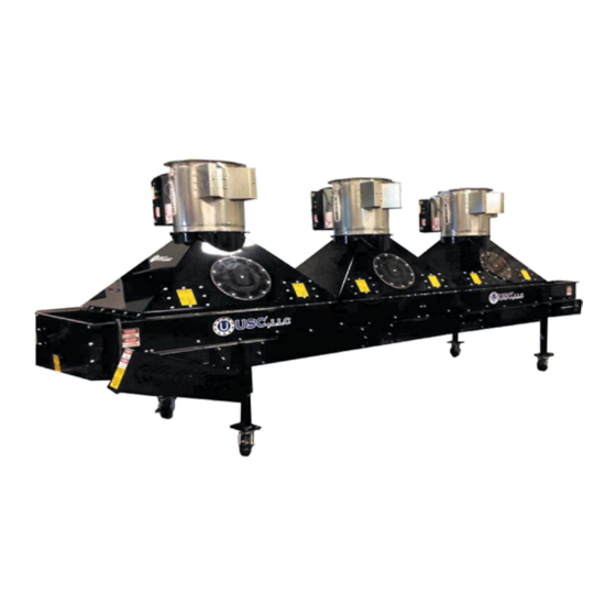
SEED CONDITIONER Section Mechanical Operation SEED CONDITIONER OVERVIEW Fan #3 Control Panel Fan #2 Display Fan #1 Seed Leveling Gate Air Cylinder Seed Leveling Gate Belt Drive Assembly Discharge Chute Pneumatic Regulator Inlet Seed Hopper Page 17... -
Page 18: Section D
General Panel Descriptions The Seed Conditioner control panel is a 30 x 24 x10 inch enclosure that contains all of the electrical control components as well as the HMI (Human/Machine Interface) touch screen. The operator is able to control the entire system through the HMI. - Page 19 SEED CONDITIONER Seed Conditioner Panel The following pages explain the function of the touch screen controls. USC STARTUP SCREEN This screen is the first screen the operator will see after the system receives power. After 30 seconds the system will automatically advance to the Main screen.
-
Page 20: Main Screen
SEED CONDITIONER MAIN SCREEN This screen informs the operator of the status of all system motors and electrical devices and allows for control / adjustment of system operations. Page 20... -
Page 21: H-O-A Screen
SEED CONDITIONER Main Screen Button Descriptions 1. FAN 1 MOTOR STATUS INDICATOR: Informs the operator if the fan motor is being told to be on (green) or off (red) and the text will indicate which mode it is currently in. - Page 22 SEED CONDITIONER H-O-A (HAND-OFF-AUTO) SCREEN Hand-Off-Auto controls are provided for most of the automated devices in the system, and are accessed on this screen. These H-O-A buttons force the selected component to be energized (HAND), de-energized (OFF), or automatically energized by the normal logic sequence (AUTO). The HAND function will cause the component to operate independent of whatever else the system is trying to do automatically.
- Page 23 SEED CONDITIONER H-O-A Button Descriptions 1. FAN 1 CONTROL MODULE: This module controls the function of fan #1. The HAND button will place the fan in the manual mode of operation. The OFF button will turn the fan in the OFF mode of operation. The AUTO button will place the device in the automatic mode of operation.
-
Page 24: Utilities Screen
SEED CONDITIONER UTILITIES SCREEN This screen allows the operator to set various system parameters and gives access to the RECIPE EDIT and INFO screens. When buttons 1-3 are NOTICE pressed, a numeric touch pad (right) will appear allowing the operator to enter in a number for that particular parameter. - Page 25 SEED CONDITIONER 1. START DELAY TIMER: Pressing this button allows the operator to adjust the time the system will wait to start when the Auxiliary Input is detected in AUTO mode. 2. STOP DELAY TIMER: Pressing this button allows the operator to adjust the time the system will wait to shutdown when the Auxiliary Input is no longer detected in AUTO mode.
-
Page 26: Alarm And E-Stop Screen
SEED CONDITIONER ALARMS SCREEN This screen notifies the operator when an error has occurred with the system. It also defines the error so that it may be corrected. Once the problem has been fixed the operation may continue. When an alarm is active, the indicator will be illuminated as shown above on Fan 3 and the alarm text will flash red and white. - Page 27 SEED CONDITIONER If the system is in TREAT MODE, and a device has been set to a state other than AUTO, when the auxiliary input is received the warning below will be displayed. The system requires all devices to be in AUTO mode. By pressing the yellow SET ALL DEVICES TO AUTO button all devices will be set to AUTO and the startup timer will begin as long as the auxiliary input is still being received from the treater.
-
Page 28: Section E
SEED CONDITIONER Section Troubleshooting TROUBLESHOOTING Below is a table describing the most frequent problems and solutions with the USC Seed Conditioner . For further assistance, contact the USC Service department at (785) 431-7900. Problem Possible Cause Solution When control panel power switch 1. -
Page 29: Section F
Section Maintenance Proper maintenance of the Seed Conditioner is critical for peak performance, reliability and accuracy of this system. The following is a guideline for the type of maintenance and servicing that should be performed on this unit. Your environment and uses may require additional maintenance and service beyond this list to assure a reliable and safe unit. - Page 30 SEED CONDITIONER Do not operate unit without making sure it contains the correct amount of oil. Do not overfill or under fill with oil, or injury to personnel, unit or other equipment may result. CHANGING LUBRICANT: After the first 100 hours of operation, drain out initial oil and flush out the gear case with an approved non-flammable, non-toxic solvent.
-
Page 31: Wire Mesh Belt Drive Tension
This process may need to be repeated several times. Whenever tightening the belt it is recommended that the belt alignment be checked before resuming production operation of the Seed Conditioner. Loosen these jam nuts before adjusting the bearing position... -
Page 32: Wire Mesh Belt Alignment & Tracking
The following are the steps required to track a wire mesh belt. 1. Make certain the Seed Conditioner unit has been carefully aligned following the procedure described above and the diagrams on page 32. - Page 33 SEED CONDITIONER BELT ADJUSTMENTS - ALIGNMENT - TRACKING Page 33...
- Page 34 SEED CONDITIONER BOTTOM OF BELT TOP OF BELT SUPPORT LAYOUTS SUPPORT LAYOUTS WIRE MESH BELT INSTALLATION If a new wire mesh belt needs to be installed, contact the USC Service department at (785) 431-7900. Page 34...
-
Page 35: Section G
Section Storage When storing the Seed Conditioner for long periods of time, the following procedure must be followed to reduce the chance of rust, corrosion and fatigue. You can also use these steps when storing the machine for the winter. - Page 36 SEED CONDITIONER NOTES: Page 36...
-
Page 37: Section H
SEED CONDITIONER Section Mechanical Drawings TAIL END LEG ASSEMBLY (05-05-0120) Item # Part # Description 01-06-0060 WHL CSTR 6.0 X 2.0 SWVL L0CK PHEN 05-05-0106 WDMT LEG ADJ SHORT 3013 DRYER 06-01-0232 BOLT FLG .500-13 X 1.250 ZP GR5 06-03-0015 NUT LOCK FLG .500-13 ZP GR5... - Page 38 SEED CONDITIONER DRIVE END LEG ASSEMBLY (05-05-0119) Item # Part # Description 01-06-0060 WHL CSTR 6.0 X 2.0 SWVL L0CK PHEN 05-05-0107 WDMT LEG ADJ TALL 3013 DRYER 06-01-0232 BOLT FLG .500-13 X 1.250 ZP GR5 06-03-0015 NUT LOCK FLG .500-13 ZP GR5 06-09-0002 PIN CLIP HITCH 3.063 SIZE 9 ZP...
- Page 39 SEED CONDITIONER DISCHARGE CHUTE ASSEMBLY (05-03-1625) Item Item # Part # Description WDMT CHUTE DSCHG DRYER 05-07-0842 06-01-0004 BOLT, .250-20 X .500 UNC ZP GRADE 5 06-01-0122 BOLT, CARRIAGE, .250-20x.75 G5 ZP 06-03-0001 NUT,LOCK, .250-20 ZP G5 NYLON INSERT 06-03-0013 NUT,LOCK, FLG .250-20 ZP SERRATTED...
- Page 40 SEED CONDITIONER BELT DRIVE ASSEMBLY (05-03-1566) Page 40...
- Page 41 KEY .250 X 3 18-8 SS 05-03-1477 WDMT MNT GBOX 05-06-0102 GRD BACK DRYER 05-06-0117 WDMT DRV GRD SEED CONDITIONER 05-11-0405 SHAFT DRV BELT RLR DRYER 06-01-0102 BOLT .313-18 X 1.25 ZP GR5 06-01-0124 BOLT FLG .375-16 X .750 ZP GR5 06-01-0127 BOLT CRG .375-16 X 1.25 ZP GR5...
- Page 42 BOLT FLG .3125-18 X .500 ZP GR5 TITLE: ASSY 3613 HOOD GSI FAN PROPRIETARY PROPERTY OF DECIMALS: X.XX +/- .06", X.XXX +/-.031 USC, LLC. AND SHALL NOT BE etha, Kansas 66534 USA 06-03-0019 NUT LOCK FLG .3125-18 ZP GR5 USED WITHOUT PERMISSION.
- Page 43 FILENAME: 05-03-1671 = 1 GSI Inlet THIS MATERIAL IS THE TOLERANCES CONFIDENTIAL AND FRACTIONS: +/- 1/8" TITLE: ASSY 3613 INLET HOOD GSI FAN PROPRIETARY PROPERTY OF DECIMALS: X.XX +/- .06", X.XXX +/-.031 USC, LLC. AND SHALL NOT BE USED WITHOUT PERMISSION. ANGLES: +/- 1°...
- Page 44 CONFIDENTIAL AND L L C. FRACTIONS: +/- 1/8" TITLE: ASSY 3613 INLET HOOD GSI FAN PROPRIETARY PROPERTY OF DECIMALS: X.XX +/- .06", X.XXX +/-.031 USC, LLC. AND SHALL NOT BE a, Kansas 66534 USA USED WITHOUT PERMISSION. ANGLES: +/- 1°...
- Page 45 SEED CONDITIONER FAN #1 - GSI FAN INLET HOOD ASSEMBLY (05-03-1671) Item # Part # Description 01-13-0022 FAN AXIAL 18IN 1.5HP 240V 3PH 02-02-0049 FLTR EXHAUST BRZ .125 NPT 02-03-0008 TBG .250 OD POLYE COMP 02-16-0044 FTTG PUSH 90 DEG .250OD X .250 NPT 02-16-0046 FTTG PUSH 90 DEG .250 OD X .125 NPT...
- Page 46 SEED CONDITIONER FRAME ASSEMBLY (05-03-1562) Page 46...
- Page 47 SEED CONDITIONER FRAME ASSEMBLY (05-03-1562) DETAIL A Page 47...
- Page 48 SEED CONDITIONER FRAME ASSEMBLY (05-03-1562) Item # Part # Description 01-03-0066 BRG STAMPED FLG 1.125 BORE 2 BOLT 01-06-0146 RLR CNVR 2.50 OD 36.00 W .437 HEX 05-03-1473 WDMT SPCR CROSS 05-03-1475 WDMT FR DRYER LT 05-03-1476 WDMT FR DRYER RT...
- Page 49 SEED CONDITIONER CONTROL PANEL MOUNT ASSEMBLY (05-07-0796) Item # Item # Part # Description 06-01-0115 BOLT CRG .375-16 X 1.00 ZP GR5 06-01-0189 BOLT, FLG .375-16 UNC ZP GRADE 5; 1-1/4" LG 06-03-0014 NUT LOCK FLG .375-16 ZP GR5 06-09-0002 PIN CLIP HITCH 3.063 SIZE 9 ZP...
- Page 50 SEED CONDITIONER SEED CONDITIONER BASE ASSEMBLY (13-16-0003) Page 50...
- Page 51 SEED CONDITIONER SEED CONDITIONER BASE ASSEMBLY (13-16-0003) DETAIL D Page 51...
- Page 52 SEED CONDITIONER SEED CONDITIONER BASE ASSEMBLY (13-16-0003) THIS MAT THIS MAT DRAWN DRAWN CHECKED CHECKED ENG APPR ENG APPR UNLESS OTHER UNLESS OTHER TOLERANCES: TOLERANCES: FRACTIONS FRACTIONS ± 1/16 ± 1/16 Page 52...
- Page 53 SEED CONDITIONER SEED CONDITIONER BASE ASSEMBLY (13-16-0003) Page 53...
- Page 54 SEED CONDITIONER SEED CONDITIONER BASE ASSEMBLY (13-16-0003) Item # Part # Description SPKT 17T 2042P X 1.125 KWY* 01-02-0140 01-02-0141 SPKT 17T 2042P X 1.125ID BUSHING* 01-03-0031 BRG FLG MNT 1.125ID 2BOLT 01-05-0011 SHAFT CLR 1.125ID SPLT 01-06-0175 RLR IDLER 5.00OD X 1.125ID X 35 01-10-0005 1/4"...
- Page 55 SEED CONDITIONER SEED CONDITIONER BASE ASSEMBLY (13-16-0003) Item # Part # Description 05-03-1625 ASSY DSCHG CHUTE SEED COND 05-03-1670 ASSY 3613 HOOD GSI FAN 05-03-1671 ASSY 3613 INLET HOOD GSI FAN 05-05-0119 ASSY LEG DRV END 05-05-0120 ASSY LEG TAIL END...
- Page 56 BOLT FLG .375-16 X .750 ZP GR5 06-01-0124 06-03-0014 NUT LOCK FLG .375-16 ZP GR5 13-16-0003 BASE ASSY 3613 SEED COND SEE TABLE 1 SEED CONDITIONER MAIN CNTRL PNL TABLE 1 Top Assembly # Part # Description 13-16-0004 03-12-0380 CONTROL PANEL 230V 1PH...
-
Page 57: Section I
Section USC Limited Warranty USC, LLC, (Manufacturer) warrants its seed treating equipment as follows: 1. Limited Warranty: Manufacturer warrants that the Products sold hereunder will be free from defects in material and workmanship for a period of 18 months from date of shipment. - Page 58 SEED CONDITIONER USC, LLC 2320 124th road Sabetha, KS 66534 PHONE: (785) 431-7900 FAX: (785) 431-7950 EMAIL: sales-team@uscllc.com WEB: www.uscllc.com Page 58...
Need help?
Do you have a question about the SEED CONDITIONER and is the answer not in the manual?
Questions and answers