Table of Contents
Advertisement
Quick Links
UG-2021-24
EVAL-M7-HVMOS-INV user guide
Evaluation power board with M7 connector
About this document
Scope and purpose
This user guide provides an overview of the evaluation board EVAL-M7-HVMOS-INV, including its main features,
key technical data, pin assignments, and mechanical dimensions.
EVAL-M7-HVMOS-INV is an evaluation power board with Infineon's latest CoolMOS™ PFD7 super-junction
MOSFETs. This board features and demonstrates Infineon's CoolMOS™ PFD7 technology for inverter circuitry at
hard switching conditions. The CoolMOS™ PFD7 optimizes switching and conduction losses to achieve high
efficiency. The MOSFETs used on this board are in a SOT-223 package. This board is suitable for driving fans,
pumps, and other smaller motors. The output power is up to 300 W with a heatsink at 16 kHz carrier frequency.
The evaluation board EVAL-M7-HVMOS-INV was developed to support users during their first steps in designing
applications with running permanent magnet motors via sensorless sinusoidal field-oriented control.
Intended audience
This evaluation board is intended for all technical specialists who are familiar with motor control and power
electronics converter systems. This board is intended to be used under laboratory conditions.
Evaluation board
This board will be used during the design-in phase, for evaluation and measurement of characteristics, and
proof of data-sheet specifications.
Note:
PCB and auxiliary circuits are NOT optimized for final customer design.
User guide
Please read the Important notice and the Safety precautions and the Warnings
Revision 1.0
www.infineon.com
page 1 of 30
2021-06-28
Advertisement
Table of Contents

Related Manuals for Infineon EVAL-M7-HVMOS-INV


Summary of Contents for Infineon EVAL-M7-HVMOS-INV
-
Page 1: About This Document
About this document Scope and purpose This user guide provides an overview of the evaluation board EVAL-M7-HVMOS-INV, including its main features, key technical data, pin assignments, and mechanical dimensions. EVAL-M7-HVMOS-INV is an evaluation power board with Infineon’s latest CoolMOS™ PFD7 super-junction MOSFETs. -
Page 2: Important Notice
Boards provided by Infineon Technologies. The design of the Evaluation Boards and Reference Boards has been tested by Infineon Technologies only as described in this document. The design is not qualified in terms of safety requirements, manufacturing and operation over the entire operating temperature range or lifetime. -
Page 3: Safety Precautions
EVAL-M7-HVMOS-INV user guide Evaluation power board with M7 connector Safety precautions Safety precautions Note: Please note the following warnings regarding the hazards associated with development systems. Table 1 Safety precautions Warning: The DC link potential of this board is up to 1000 VDC. When measuring voltage waveforms by oscilloscope, high voltage differential probes must be used. -
Page 4: Table Of Contents
EVAL-M7-HVMOS-INV user guide Evaluation power board with M7 connector Table of contents Table of contents About this document ........................1 Important notice ..........................2 Safety precautions .......................... 3 Table of contents ..........................4 The board at a glance ......................5 Scope of supply ............................ -
Page 5: The Board At A Glance
The board at a glance The EVAL-M7-HVMOS-INV is an evaluation power board with an M7 connector. Please refer to Chapter 2.2.1 for details of the M7 connector pinout assignment. This evaluation power board was designed to be driven by a control board that is compatible with the M7 connector. -
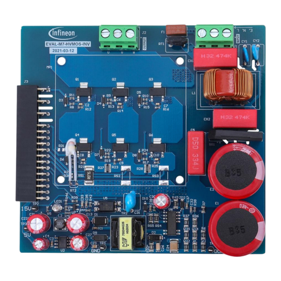
Page 6: Scope Of Supply
The scope of supply comprises only the board, as shown in Figure 1. The detailed ordering information is indicated inTable 2. If users do not have a control board, the Infineon smart-driver control board EVAL-M7-D111T can be used to evaluate the power board. Ordering information can be found in the following link. -
Page 7: Main Features
The board at a glance Main features EVAL-M7-HVMOS-INV is an evaluation board using Infineon’s 600 V CoolMOS™ PFD7 high-voltage MOSFET. This board is suitable for permanent magnet synchronous motor or brushless direct current motor (PMSM or BLDC) control for home appliances, fans, pumps, etc. -
Page 8: System And Functional Description
(MCE) that can be implemented as a ready-to-use solution for variable speed drives. Users who would like to drive the power board with the EVAL-M7-D111T control board can find more details in the Infineon user guide UG-2021-17. The IMD111T control board user guide describes how to use iMOTION tools to run the board. -
Page 9: Mcewizard Setup Overview
EVAL-M7-HVMOS-INV user guide Evaluation power board with M7 connector System and functional description 5. Power-on the system and start the MCEDesigner tool to open MCEDesigner default configuration file (.irc) for the IMD111T smart driver. 6. Program the firmware and calculated parameters into the flash. See the MCEDesigner setup overview in Chapter 2.2.1.2 for more details. - Page 10 EVAL-M7-HVMOS-INV user guide Evaluation power board with M7 connector System and functional description Table 4 lists key questions to be answered in the MCEWizard in order to set up the system based on the evaluation board. The remaining set of questions also needs to be answered, including questions about OV/UV protection, fault conditions, startup setting, etc.
-
Page 11: Mcedesigner Setup Overview
Then click the Start button to program the ldf and text files. The ldf file can be downloaded from the Infineon website. The txt file was created by the MCEWizard as described in Chapter 2.2.1.1. The programming window is shown in Figure 7 below. -
Page 12: Description Of The Functional Blocks
Programming window Description of the functional blocks This chapter covers the hardware design of the EVAL-M7-HVMOS-INV in more detail, so that users can understand the functional groups of this power board and use the board to easily evaluate the performance. - Page 13 Rectifier bridge & bus capacitors (E1, E2, BR1) Auxiliary power supply (U2, U6, TR2) M7 connector (J2) There are 3 connectors on the EVAL-M7-HVMOS-INV board. All connector pin assignments are described in Table 5 to Table 7. Table 5 220V...
-
Page 14: Bus Voltage Feedback
2.3.2 Bus voltage feedback The EVAL-M7-HVMOS-INV evaluation board includes a bus voltage feedback circuitry. It is a voltage divider. The high-side resistor is composed of two 1 MΩ resistors (R3, R6) in series, and the low-side resistor (R7) is composed of one 20 kΩ. Figure 9 shows the bus voltage feedback on the board. Make sure the low-side resistor is on this power board, which is different from some other power boards that have the low-side resistor on the control board. -
Page 15: Current Feedback Configuration
2.3.3 Current feedback configuration There are two current feedback configurations on this EVAL-M7-HVMOS-INV power board. One is a single-shunt current feedback configuration. The other is a leg-shunt current feedback configuration. The single shunt configuration is the default setting on the board. If users want to use a leg-shunt configuration, they should remove the resistors R26, R27, and R27 first. - Page 16 EVAL-M7-HVMOS-INV user guide Evaluation power board with M7 connector System and functional description According to the connection shown in Figure 11, the NTC character on the board has been tested to observe the relationship between the dropped voltage of the NTC resistor and the maximum MOSFET case temperature. In this way, users can get the hottest MOSFET temperature by measuring the NTC dropped voltage.
-
Page 17: Dc Power Supply
2.3.5 DC power supply This evaluation board EVAL-M7-HVMOS-INV is dedicated to motor applications under 300 W at 220 V input. It is designed using two 82 µF bus capacitors. If this board is being used to evaluate higher power over 300 W, users should consider the effect of the higher bus voltage ripple at heavy load. -
Page 18: System Design
Figure 15 shows the inverter section schematics of the EVAL-M7-HVMOS-INV. Figure 16 depicts the auxiliary power supply schematics. The power supply has two outputs: 15 V and 5 V. The complete schematic diagrams are available on the download section of the Infineon homepage. A log-in is required to download this material. -
Page 19: Layout
The EVAL-M7-HVMOS-INV board consists of two copper PCB layers. The copper thickness is 35 μm and the board size is 103 mm x 96 mm. The board material is FR4 grade with 1.6 mm thickness. Check Infineon’s website or contact Infineon’s technical support team for more detailed information. The Gerber files are available on the download section of the Infineon homepage. -
Page 20: Bill Of Material
Figure 18 Bottom layer Bill of material The complete bill of material is available on the download section of the Infineon homepage. A log-in is required to download this material. Table 9 is the BOM of EVAL-M7-HVMOS-INV board. Table 9 BOM of the evaluation board EVAL-M7-HVMOS-INV S. - Page 21 EVAL-M7-HVMOS-INV user guide Evaluation power board with M7 connector System design S. No. Ref Designator Description Manufacturer Manufacturer P/N CAP / ELCO / 82 uF / 450 V / 20% / - / - Wurth E1, E2 861021483005 25℃ to 105℃ /...
- Page 22 EVAL-M7-HVMOS-INV user guide Evaluation power board with M7 connector System design S. No. Ref Designator Description Manufacturer Manufacturer P/N 7.00mm L X 7.00mm T X 10.00mm H / THT / - C2, C6, C7, CAP / CERA / 1nF / 50V / 1% / C0G (EIA) /...
- Page 23 EVAL-M7-HVMOS-INV user guide Evaluation power board with M7 connector System design S. No. Ref Designator Description Manufacturer Manufacturer P/N pin, 13.80 mm L X 23.00 mm W X 25.50 mm H body / THT / - Wurth 7.45E+08 IND / STD / 2.2uH / 2.5A / 20% / -40℃...
- Page 24 EVAL-M7-HVMOS-INV user guide Evaluation power board with M7 connector System design S. No. Ref Designator Description Manufacturer Manufacturer P/N RES / STD / 62k / 100mW / 1% / Vishay CRCW060362K0FK 100ppm/K / -55℃ to 155℃ / 0603 / SMD / - RES / STD / 1.5k / 100mW / 1% /...
- Page 25 EVAL-M7-HVMOS-INV user guide Evaluation power board with M7 connector System design S. No. Ref Designator Description Manufacturer Manufacturer P/N Optocoupler, Phototransistor Output, Vishay SFH617A-3X007T High Reliability, 5300 VRMS, 110 ℃ Rated Precision Programmable Reference Texas TL431CDBZR Instruments User guide 25 of 30 Revision 1.0...
-
Page 26: System Performance
EVAL-M7-HVMOS-INV dv/dt test waveform Thermal performance test For the EVAL-M7-HVMOS-INV power board thermal performance test, the input power and motor-phase current were measured when the MOSFET case temperature was increased to 100℃. The power board was tested in different carrier frequencies. The PWM frequency range is from 4 kHz to 16 kHz under testing conditions. Keep in mind, however, that this power board can be run up to 20 kHz;... -
Page 27: Test Results
System performance Test results The output power capability of the EVAL-M7-HVMOS-INV power board was tested at different carrier frequencies. The MOSFET case temperature is up to 100℃ under test conditions. All the tests take place at room temperature and without heatsink or cooling fan. Figure 21 shows the increase of MOSFET case temperature in relation to input power at different PWM frequencies. -
Page 28: References And Appendices
Infineon Technologies AG. Datasheet (2019): IPN60R600PFD7S - 600V CoolMOSª PFD7 SJ Power Device. V2.0 www.infineon.com Infineon Technologies AG. Datasheet (2018): ICE5GR4780AG - Fixed frequency 700 V/800 V CoolSET™ - in DSO-12 Package. V2.2 WWW.infineon.com [3] Vishay. Datasheet (2020): NTCLE100E3, NTC thermistors. V 18-Sep-2020. -
Page 29: Revision History
EVAL-M7-HVMOS-INV user guide Evaluation power board with M7 connector Revision history Revision history Document Date of release Description of changes version V1.0 2021-06-28 First release User guide 29 of 30 Revision 1.0 2021-06-28... - Page 30 WARNINGS 81726 Munich, Germany Due to technical requirements products may contain dangerous substances. For information on the types in question please contact your nearest Infineon © 2021 Infineon Technologies AG. Technologies office. All Rights Reserved. Except as otherwise explicitly approved by Infineon...
- Page 31 Mouser Electronics Authorized Distributor Click to View Pricing, Inventory, Delivery & Lifecycle Information: Infineon EVALM7HVMOSINVTOBO1...
Need help?
Do you have a question about the EVAL-M7-HVMOS-INV and is the answer not in the manual?
Questions and answers