Table of Contents
Advertisement
Quick Links
UG-2023-05
EVAL-M7-HVIGBT-PFCINV user guide
Evaluation power board with M7 connector
About this document
This user guide provides an overview of the evaluation board EVAL-M7-HVIGBT-PFCINV, including its main
features, key-technical data, pin assignments, and mechanical dimensions.
The board name, EVAL-M7-HVIGBT-PFCINV, contains two different boards — EVAL-M7-HVIGBT-PFCINV1
and EVAL-M7-HVIGBT-PFCINV4. The last number 1 in the board name represents a power factor control
(PFC) frequency of 100 kHz, and the number 4 represents a PFC frequency of 40 kHz. Every mention of EVAL-
M7-HVIGBT-PFCINV includes both EVAL-M7-HVIGBT-PFCINV1 and EVAL-M7-HVIGBT-PFCINV4 boards unless
specified otherwise.
Scope and purpose
EVAL-M7-HVIGBT-PFCINV includes Infineon's TRENCHSTOP™ IGBTs. It features and demonstrates Infineon's
TRENCHSTOP™ IGBT technology for PFC and inverter circuitry in hard-switching conditions. The
TRENCHSTOP™ IGBT optimizes switching and conduction losses to reach a high efficiency. The IGBTs used on
this board are in D
The evaluation board EVAL-M7-HVIGBT-PFCINV was developed to support users during their first steps in
designing applications with running any permanent magnet motor via sensor-less sinusoidal field-oriented
control.
Intended audience
This evaluation board is intended for all technical specialists who are familiar with motor control and power
electronics converter systems.
Evaluation board
EVAL-M7-HVIGBT-PFCINV is meant to be used during the design-in process for evaluating and measuring the
board characteristic curves, and checking datasheet specifications. It is intended only to be used under
laboratory conditions.
Note:
The printed circuit board (PCB) and auxiliary circuits are NOT optimized for final customer design.
www.infineon.com
PAK packages.
2
Please read the Important Notice and Warnings at the end of this document
V1.0
2023-6-30
Advertisement
Table of Contents

Related Manuals for Infineon EVAL-M7-HVIGBT-PFCINV


Summary of Contents for Infineon EVAL-M7-HVIGBT-PFCINV
-
Page 1: About This Document
This evaluation board is intended for all technical specialists who are familiar with motor control and power electronics converter systems. Evaluation board EVAL-M7-HVIGBT-PFCINV is meant to be used during the design-in process for evaluating and measuring the board characteristic curves, and checking datasheet specifications. It is intended only to be used under laboratory conditions. -
Page 2: Important Notice
Boards provided by Infineon Technologies. The design of the Evaluation Boards and Reference Boards has been tested by Infineon Technologies only as described in this document. The design is not qualified in terms of safety requirements, manufacturing and operation over the entire operating temperature range or lifetime. -
Page 3: Safety Precautions
EVAL-M7-HVIGBT-PFCINV user guide Evaluation power board with M7 connector Safety precautions Safety precautions Note: Please note the following warnings regarding the hazards associated with development systems. Safety precautions Table 1 Warning: The DC link potential of this board is up to 1000 VDC. When measuring voltage waveforms by oscilloscope, high voltage differential probes must be used. -
Page 4: Table Of Contents
Board parameters and technical data ....................9 System and functional description ..................10 Getting started ............................10 Description of the functional blocks ..................... 10 2.2.1 Functional groups of EVAL-M7-HVIGBT-PFCINV ................10 2.2.2 Voltage feedback ..........................13 2.2.3 Temperature measured with NTC on board ................... 14 2.2.4... -
Page 5: The Board At A Glance
EVAL-M7-HVIGBT-PFCINV user guide Evaluation power board with M7 connector The board at a glance The board at a glance The evaluation power board described in this user guide includes two boards — EVAL-M7-HVIGBT-PFCINV1 and EVAL-M7-HVIGBT-PFCINV4. The EVAL-M7-HVIGBT-PFCINV1 has a 100 kHz PFC and EVAL-M7-HVIGBT-PFCINV4 has a 40 kHz PFC. -
Page 6: Scope Of Supply
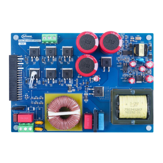
EVAL-M7-HVIGBT-PFCINV user guide Evaluation power board with M7 connector The board at a glance Figure 2 EVAL-M7-HVIGBT-PFCINV1 evaluation board Scope of supply The delivery box only contains the board as shown in Figure 1 (40 kHz PFC) or Figure 2 (100 kHz PFC). The detailed ordering information is listed in Table 1. -
Page 7: Block Diagram
EVAL-M7-D112T. IMD112T has an output capability of 5 V with a maximum output current of 10 mA. The 5 V power supply on the EVAL-M7-HVIGBT-PFCINV board is optional depending on the application’s needs for more current output capability, or if the control board used by the user is without a 5 V output power supply. -
Page 8: Main Features
- Very high switching speed Low EMI • Pb-free plating • Main features of the EVAL-M7-HVIGBT-PFCINV evaluation power board are: Boost PFC topology • Supports 40 kHz and 100 kHz PFC depending on the power board • Direct current feedback for the both PFC and inverter •... -
Page 9: Board Parameters And Technical Data
EVAL-M7-HVIGBT-PFCINV user guide Evaluation power board with M7 connector The board at a glance Board parameters and technical data Table 2 lists the evaluation board’s parameters and technical details. Parameter Table 2 Parameter Symbol Conditions Value Unit Input AC voltage... -
Page 10: System And Functional Description
System and functional description Getting started The EVAL-M7-HVIGBT-PFCINV evaluation board is only a power board with boost PFC and has no control function. Therefore, it should be used with an M7 connector-compatible control board. Figure 4 is an example of the system setup with Infineon iMOTION smart driver IMD112T control board EVAL-M7-D112T. - Page 11 5. Auxiliary power supply 6. PFC inductor 7. AC input connector, EMI filter, and rectifier bridge There are three connectors on the EVAL-M7-HVIGBT-PFCINV board. All connector pin assignments are listed in Table 3 to Table 5. 220 VAC input connector-J1...
- Page 12 EVAL-M7-HVIGBT-PFCINV user guide Evaluation power board with M7 connector System and functional description Inverter output connector-J2 Table 4 Pin number Symbol Assignment W phase output V phase output U phase output M7 connector -J3 Table 5 Pin number Symbol Assignment...
-
Page 13: Voltage Feedback
2.2.2 Voltage feedback The EVAL-M7-HVIGBT-PFCINV evaluation board includes AC line voltage and DC bus voltage feedback circuits. They both are voltage dividers. The DC bus voltage feedback high-side resistor is composed of three 680 kΩ resistors (R4, R6, R39) in series, and the low-side resistor (R8) is a single 13.3 kΩ resistor. AC line voltage feedback is composed of two high-side resistors (1 MΩ) and one low-side resistor (15 kΩ). -
Page 14: Temperature Measured With Ntc On Board
EVAL-M7-HVIGBT-PFCINV user guide Evaluation power board with M7 connector System and functional description 2.2.3 Temperature measured with NTC on board To measure the case temperature of the IGBT switch, a negative temperature coefficient (NTC) resistor is located on the surface of the U phase, low-side IGBT on the board. NTC’s placement on the board is as shown in Figure 7. -
Page 15: Protection Function
2.2.4 Protection function There is no external hardware protection function onboard for EVAL-M7-HVIGBT-PFCINV. Protection functions such as overcurrent, over and undervoltage, phase loss, and rotor lock are all carried out by the control board when EVAL-M7-D112T control board is used for evaluation. Overcurrent and overvoltage/undervoltage protection thresholds can be set using a wizard. -
Page 16: System Design
System design Schematics The schematics of EVAL-M7-HVIGBT-PFCINV power board include an EMI filter, a rectifier bridge, boost PFC, inverter section, and an auxiliary power supply. Figure 9 shows the boost PFC schematics of EVAL-M7-HVIGBT- PFCINV4. Figure 10 shows the inverter section schematics and Figure 11 shows the auxiliary power supply schematics. - Page 17 EVAL-M7-HVIGBT-PFCINV user guide Evaluation power board with M7 connector System design IKB06N60T IKB06N60T 220R IKB06N60T 220R 220R 1N4148W-13-F 1N4148W-13-F 1N4148W-13-F 691216510003S IKB06N60T IKB06N60T IKB06N60T 220R 220R 220R 1N4148W-13-F 1N4148W-13-F 1N4148W-13-F 75mR Figure 10 Inverter schematics of EVAL-M7-HVIGBT-PFCINV4 +15V X200 D202...
-
Page 18: Layout
The EVAL-M7-HVIGBT-PFCINV board consists of two copper PCB layers. The copper thickness is 35 μm and the board size is 153 mm x 107 mm. The board material is of FR4 grade with 1.6 mm thickness. Check Infineon’s website or contact Infineon’s technical support team for detailed information. Gerber files are available on Infineon’s website in the download section. -
Page 19: Bill Of Material
Bill of material The bill of material is available on Infineon’s website in the download section. Login credentials are required to download this material. Table 7 lists the combined BOMs of the two power boards. The differences are listed in line items 34 and 51. - Page 20 EVAL-M7-HVIGBT-PFCINV user guide Evaluation power board with M7 connector System design Description Manufacturer Manufacturer P/N Designator 5 C10 CAP / CERA / 100nF / 50V / 10% / X7R (EIA) / -55 C2012X7R1H104K085A Corporation ℃ to 125℃ / 0805(2012) / SMD / -...
- Page 21 EVAL-M7-HVIGBT-PFCINV user guide Evaluation power board with M7 connector System design Description Manufacturer Manufacturer P/N Designator 24 D1 Schottky Diode, 5th Generation ThinQ SiC Infineon IDK04G65C5 Technologies 25 D4, D5, D6, Surface Mount Fast Switching Diode Diodes 1N4148W-13-F D7, D8, D9,...
- Page 22 EVAL-M7-HVIGBT-PFCINV user guide Evaluation power board with M7 connector System design Description Manufacturer Manufacturer P/N Designator R36, R37, 42 R7, R20 RES / STD / 10k / 100mW / 1% / 100ppm/K / -55 Vishay CRCW060310K0FK ℃ to 155℃ / 0603 / SMD / - 43 R8 RES / STD / 13.3k / 100mW / 1% / 100ppm/K / -...
- Page 23 EVAL-M7-HVIGBT-PFCINV user guide Evaluation power board with M7 connector System design Description Manufacturer Manufacturer P/N Designator 61 R213 RES / STD / 22k / 100mW / 1% / 100ppm/K / -55 Vishay CRCW060322K0FK ℃ to 155℃ / 0603 / SMD / - 62 R214 RES / STD / 48.7k / 100mW / 1% / 100ppm/K / -...
-
Page 24: System Performance
This is a trade-off between switching losses and dv/dt. For the PFC turn-on dv/dt, there is a different gate resistor to balance the dv/dt and switching losses for EVAL-M7-HVIGBT-PFCONV4 and EVAL-M7-HVIGBT- PFCINV1. The inverter turn-on dv/dt of the EVAL-M7-HVIGBT-PFCINV board is measured at 1.58 V/ns. Figure 14 shows the inverter dv/dt test waveform. - Page 25 EVAL-M7-HVIGBT-PFCINV user guide Evaluation power board with M7 connector System performance 45° Wind speed test point Figure 15 Cooling fan location for the test PFC switch IGBT PFC switch IGBT 100 kHz inductor inductor 40 kHz Rectifier Inverter bridge Inverter...
-
Page 26: Pfc Test Results
IMD112T control board, EVAL-M7-D112T. Please refer to the EVAL-M7-D112T control board’s user guide, UG- 2023-04, for more details [4].The EVAL-M7-HVIGBT-PFCINV power board can support up to 200 W output power with natural cooling and 400 W output power with force cooling (24 V /0.18 A cooling fan). - Page 27 EVAL-M7-HVIGBT-PFCINV user guide Evaluation power board with M7 connector System performance waveforms for input line voltage and current, DC bus voltage, PFC inductor current, and inverter phase current at 400 W input power. 40 kHz PFC IGBT case temperature ∆T...
- Page 28 EVAL-M7-HVIGBT-PFCINV user guide Evaluation power board with M7 connector System performance Inverter IGBT case temperture increment at different PWM 6 kHz 10 kHz 15 kHz Inverter phase current(Arms) Figure 19 Inverter IGBT case temperature ΔT versus output phase current at different carrier...
- Page 29 EVAL-M7-HVIGBT-PFCINV user guide Evaluation power board with M7 connector System performance Figure 21 Line voltage (blue), line current (red), DC bus voltage (yellow), PFC inductor current (green) at 100 kHz PFC PWM, 220 Vac input, 400 W output (2.1 Arms phase current)
-
Page 30: Appendices
EVAL-M7-HVIGBT-PFCINV user guide Evaluation power board with M7 connector Appendices Appendices Abbreviations and definitions Abbreviations Table 9 Abbreviation Meaning Total harmonic distortion Electromagnetic interference Power factor correction Power factor iMOTION™ Solution Designer Field oriented control V1.0 2023-6-30... -
Page 31: References
[2] Infineon Technologies AG. Datasheet (2013): IKB06N60T – TRENCHSTOP and FieldStop technology with soft, fast recovery anti-paralled Emitter Controlled HE diode. V2.5 www.infineon.com [3] Infineon Technologies AG. User manual (2022): Getting Started with iMOTION™ Solution Designer. www.infineon.com [4] Infineon Technologies AG. User guide (2023): EVAL-M7-D112T user guide. www.infineon.com V1.0... -
Page 32: Revision History
EVAL-M7-HVIGBT-PFCINV user guide Evaluation power board with M7 connector Revision history Revision history Document Date Description of changes version V1.0 2023-6-30 First version V1.0 2023-6-30... -
Page 33: Disclaimer
Due to technical requirements products may contain Published by dangerous substances. For information on the types Infineon Technologies AG in question please contact your nearest Infineon Technologies office. 81726 Munich, Germany Except as otherwise explicitly approved by Infineon Technologies in a written document signed by ©...
Need help?
Do you have a question about the EVAL-M7-HVIGBT-PFCINV and is the answer not in the manual?
Questions and answers