Table of Contents
Advertisement
Quick Links
AN2016-15 EVAL-M1-36-45A User Manual
EVAL-M1-36-45A User Manual
iMOTION™ Modular Application Design Kit
About this document
Scope and purpose
This application note provides an overview of the evaluation board EVAL-M1-36-45A including its main features,
key data, pin assignments and mechanical dimensions.
The board is available in two versions.
EVAL-M1-36-45A is a complete evaluation-board including a 3-phase IPM for motor drive applications. Together
with EVAL-M1-101T or EVAL-M1-099M it features and demonstrates Infineon's IPM technology for motor drives.
The evaluation board EVAL-M1-36-45A for Intelligent Power Modules (IPM) was developed to support customers
during their first steps designing applications with CIPOS™ Nano power modules.
Intended audience
This application note is intended for all technical specialists working with the EVAL-M1-36-45A board.
Table of Contents
About this document ....................................................................................................................... 1
Table of Contents ........................................................................................................................... 1
1
Safety precautions ......................................................................................................... 2
2
Introduction .................................................................................................................. 4
3
Design features ............................................................................................................. 6
3.1
Key data ................................................................................................................................................... 7
4
Pin Assignments ........................................................................................................... 11
5
Getting Started with EVAL-M1-36-45A ............................................................................. 13
5.1
Setting up the system............................................................................................................................ 13
5.2
iMOTION™ development tools and software ....................................................................................... 15
5.2.1
MCEWizard setup overview .............................................................................................................. 15
5.2.2
MCEDesigner setup overview .......................................................................................................... 17
6
Schematics and Layout .................................................................................................. 19
6.1
DC-Link Voltage Measurement ............................................................................................................. 19
6.2
Inverter section using CIPOS™ Nano IPM ............................................................................................. 20
6.3
Current Measurement and Over Current Circuit .................................................................................. 21
6.4
Auxiliary Power supply .......................................................................................................................... 22
6.5
PCB Layout ............................................................................................................................................ 23
7
Bill of Materials of EVAL-M1-36-45A ................................................................................. 25
8
Reference .................................................................................................................... 28
Revision History ............................................................................................................................ 29
User Manual
www.infineon.com
Please read the Important Notice and Warnings at the end of this document
Revision 1.2
2018-09-23
Advertisement
Table of Contents

Related Manuals for Infineon iMOTION EVAL-M1-36-45A


Summary of Contents for Infineon iMOTION EVAL-M1-36-45A
-
Page 1: Table Of Contents
EVAL-M1-36-45A is a complete evaluation-board including a 3-phase IPM for motor drive applications. Together with EVAL-M1-101T or EVAL-M1-099M it features and demonstrates Infineon’s IPM technology for motor drives. The evaluation board EVAL-M1-36-45A for Intelligent Power Modules (IPM) was developed to support customers during their first steps designing applications with CIPOS™... -
Page 2: Safety Precautions
EVAL-M1-36-45A User Manual iMOTION™ Modular Application Design Kit Safety precautions Safety precautions In addition to the precautions listed throughout this manual, please read and understand the following statements regarding hazards associated with development systems. Precautions Table 1 Attention: The ground potential of the EVAL-M1-36-45A system is biased to a negative DC bus voltage potential. - Page 3 EVAL-M1-36-45A User Manual iMOTION™ Modular Application Design Kit Safety precautions Attention: EVAL-M1-36-45A system is shipped with packing materials that need to be removed prior to installation. Failure to remove all packing materials which are unnecessary for system installation may result in overheating or abnormal operating condition.
-
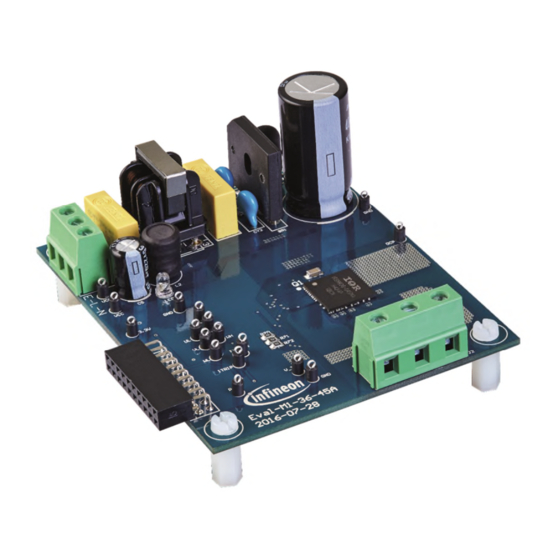
Page 4: Introduction
DC-link voltage measurement. The EVAL-M1-36-45A evaluation board is available from Infineon. The features of this board are described in the design feature chapter of this document, whereas the remaining paragraphs provide information to enable the customers to copy, modify and qualify the design for production, according to their own specific requirements. - Page 5 EVAL-M1-36-45A User Manual iMOTION™ Modular Application Design Kit Introduction Figure 1 shows the evaluation board Eval-M1-36-45A. This board is compatible with all CIPOS™ modules. This document explains the features and details of CIPOS™ Nano IRSM836-045MA. This module is rated 500 V. Ratings and other details of the board are explained in the subsequent sections.
-
Page 6: Design Features
The following sections provide an overview of the board including main attributes, key data, pin assignments and mechanical dimensions. EVAL-M1-36-45A is a complete evaluation board including a 3-phase IPM for motor drive applications. The board demonstrates Infineon’s IPM technology for motor drives. CIPOS™ Nano Intelligent Power Module (IRSM836-045MA) features are: 3-phase inverter including high voltage gate drivers •... -
Page 7: Key Data
EVAL-M1-36-45A User Manual iMOTION™ Modular Application Design Kit Design features Key data Figure 2 provides internal electrical schematics of IRSM836-045MA. For further information regarding these IPMs like static and dynamic electrical behavior, as well as thermal and mechanical characteristics please refer to the datasheet of the IRSM836-045MA. - Page 8 EVAL-M1-36-45A User Manual iMOTION™ Modular Application Design Kit Design features Table 3 depicts the recommended operating conditions of IRSM836-045MA. Recommended operating conditions of CIPOS™ Nano IRSM836-045MA Table 3 Symbol Description Unit Positive DC Bus Input Voltage High Side Floating Supply Offset Voltage S1,2,3 High Side Floating Supply Voltage B1,2,3...
- Page 9 EVAL-M1-36-45A User Manual iMOTION™ Modular Application Design Kit Design features Table 4 shows the important specifications of the evaluation board EVAL-M1-36-45A. EVAL-M1-36-45A board specifications Table 4 Parameters Value Conditions Input Voltage 165 - 265 V lower AC input, less motor power output Input current input 220 V =25°C, IRSM836-045MA...
- Page 10 EVAL-M1-36-45A User Manual iMOTION™ Modular Application Design Kit Design features Figure 3 and Figure 4 are indicating the functional groups of the EVAL-M1-36-45A evaluation board. 1. CIPOS™ nano module 2. Motor phase connector (J3) 3. iMOTION™ M1 20 pin connector (J4) 4.
-
Page 11: Pin Assignments
EVAL-M1-36-45A User Manual iMOTION™ Modular Application Design Kit Pin Assignments Pin Assignments General information about the connectors of the EVAL-M1-36-45A evaluation board is reported. Table 5 includes the details of the line connector J1-AC. It is possible to connect DC voltage to the AC connector. In this case a permanent DC-current will be conducted through the rectifier bridge. - Page 12 EVAL-M1-36-45A User Manual iMOTION™ Modular Application Design Kit Pin Assignments Table 7 registered the pin assignments of J4, iMOTION™ -M1 20 pin interface connector. This connector is the interface to the controller board. J4 –iMOTION™ M1 20 pin interface connector to connect Eval-M1-36-45A to controller board Table 7 Name Connectors...
-
Page 13: Getting Started With Eval-M1-36-45A
Figure 5 System connection example using EVAL-M1-101T and EVAL-M1-36-45A 1. Get the latest ”IMC101T-T038 MCE Software Package” available on www.infineon.com/imotion-software web page. 2. Connect PC-USB connector on the on-board-debugger to the PC via USB cable. 3. Connect EVAL-M1-101T’s M1 20-pin interface connector (J2) to power board (For example EVAL-M1-36-45A, see Figure 5). - Page 14 EVAL-M1-36-45A User Manual iMOTION™ Modular Application Design Kit Getting Started with EVAL-M1-36-45A 7. Start MCEDesigner tool and open MCEDesigner default configuration file (.irc) for IMC101T-T038 controller (IMC101T_Vxxx.irc) by clicking “File” > “Open”. IMC101T_Vxxx.irc file is included in ”IMC101T-T038 MCE Software Package” downloaded in step 1. 8.
-
Page 15: Imotion™ Development Tools And Software
“Welcome Page” for MCEWizard, where the MADK control board or power board can be selected through the pull-down list. Infineon keeps releasing new MADK controller and power boards. Therefore, it could happen that some of the newest power boards are not pre-configured in the MCEWizard tool and cannot be selected through the pull-down menu. - Page 16 EVAL-M1-36-45A User Manual iMOTION™ Modular Application Design Kit Getting Started with EVAL-M1-36-45A Table 8 provides the MCEWizard setup overview for hardware related parameters specific to EVAL-M1-36-45A power board. Similar tables will be available in each control board’s Application Note. Combination of this table and the corresponding table of the control board provides enough information to setup the MADK-based motor drive system in shortest time.
-
Page 17: Mcedesigner Setup Overview
EVAL-M1-36-45A User Manual iMOTION™ Modular Application Design Kit Getting Started with EVAL-M1-36-45A 5.2.2 MCEDesigner setup overview After installing MCEDesigner installer, there is a shortcut for MCEDesigner on Windows desktop. Double click the shortcut to open MCEDesigner and then open “IMC101T_xx.irc” file as shown in Figure 8. Figure 8 MCEDesigner’s Main Display for EVAL-M1-101T To program Drive System Parameter file into IMC101T-T038, please click “Tools”... - Page 18 File”. Finally, click on the “Start” button to program the parameter file into the IMC101T-T038 IC. Figure 10 Program Firmware and Parameter in “Program IMC Controller” pop-up window All the latest firmware files for different types of iMOTION motor control ICs are available for download via Infineon iMOTION website (http://www.infineon.com/imotion-software). User Manual Revision 1.2 2018-09-23...
-
Page 19: Schematics And Layout
EVAL-M1-36-45A User Manual iMOTION™ Modular Application Design Kit Schematics and Layout Schematics and Layout To meet individual customer requirements and make the EVAL-M1-36-45A evaluation board a basis for development or modification, all essential technical data like schematics, layout and components are included in this chapter. -
Page 20: Inverter Section Using Cipos™ Nano Ipm
EVAL-M1-36-45A User Manual iMOTION™ Modular Application Design Kit Schematics and Layout Inverter section using CIPOS™ Nano IPM The inverter section is implemented using the CIPOS™ Nano IPM as displayed in Figure 12. The module includes six power MOSFETs and three half bridge gate drivers. The three capacitors C71, C72 and C73 are used as bootstrap capacitors to provide the necessary floating supply voltages V and V... -
Page 21: Current Measurement And Over Current Circuit
EVAL-M1-36-45A User Manual iMOTION™ Modular Application Design Kit Schematics and Layout Current Measurement and Over Current Circuit The resistors RS1 to RS3 are purposed to generate a voltage proportional to the emitter current. These voltages are available at 20 pin interface connector to give feedback to the controller. In combination with resistors R70 to R72 they are used to generate common current signal V_TRIP for all three phases. -
Page 22: Auxiliary Power Supply
EVAL-M1-36-45A User Manual iMOTION™ Modular Application Design Kit Schematics and Layout Auxiliary Power supply Figure 14 reports the schematic of the power supply available on the EVAL-M1-36-45A board. The circuit includes LNK304 that is used to generate 15V (V ) directly from the DC bus. V is connected to the gate drivers inside the CIPOS™... -
Page 23: Pcb Layout
EVAL-M1-36-45A User Manual iMOTION™ Modular Application Design Kit Schematics and Layout PCB Layout The layout of this board can be used for different voltage or power classes. The power PCB is a two layer PCB. Get in contact with our technical support team to get more detailed information and the latest Gerber-files. Figure 15 illustrates the top assembly print of the evaluation board. - Page 24 EVAL-M1-36-45A User Manual iMOTION™ Modular Application Design Kit Schematics and Layout The top layer routing of the PCB is provided in Figure 17 . Figure 17 Top layer routing details of EVAL-M1-36-45A Figure 18 illustrates the bottom layer routing details. Figure 18 Bottom layer routing details of EVAL-M1-36-45A User Manual...
-
Page 25: Bill Of Materials Of Eval-M1-36-45A
EVAL-M1-36-45A User Manual iMOTION™ Modular Application Design Kit Bill of Materials of EVAL-M1-36-45A Bill of Materials of EVAL-M1-36-45A Table 9 provides the complete bill of materials of the evaluation board. Bill of materials Table 9 No. Qty Part description Designator Part number Manufacturer RECT BRIDGE GPP 4A 600V... - Page 26 FIXED IND 2.2mH RLB0914-222KL THROUGH HOLE Wurth Electronics Inc. LED RED CLEAR ROUND 151034RS03000 LED1 IC MOTOR DRIVER PAR 37- IRSM836-045MA Infineon Technologies PQFN RES SMD 4.87 kΩ 1% 1/8W RC0805FR-074K87L Yageo 0805 (DIN) RES SMD 1 MΩ 1% 1/4W RCL06121M00JNEA Yageo...
- Page 27 EVAL-M1-36-45A User Manual iMOTION™ Modular Application Design Kit Bill of Materials of EVAL-M1-36-45A No. Qty Part description Designator Part number Manufacturer COMPARATOR 8-SOIC TEST POINT PC TP1, TP4, 5002 Keystone Electronics MINI .040"D WHITE TP2, TP3, TP5, TP8, TP9,TP10, TP11,TP12, TP13,TP14, TP15,TP16, TP21, TP24,...
-
Page 28: Reference
Modular Application Design Kit Reference Reference Datasheet of Infineon IPM IRSM836-045MA, is available for download on Infineon’s website Application Note AN2009-10 Using the NTC inside a power electronic module, is available for download on Infineon’s website EVAL-M1-101T User Manual is available for download on Infineon’s website EVAL-M1-183M User Manual is available for download on Infineon’s website... -
Page 29: Revision History
EVAL-M1-36-45A User Manual iMOTION™ Modular Application Design Kit Revision History Revision History Major changes since the last revision Version number Revision Date Revision description 2017-03-20 First release 2018-07-09 Update BOM. Add WE Part Number, and add Getting Started with EVAL-M1-36-45A 2018-09-23 Change DC input to AC input. - Page 30 The data contained in this document is exclusively Email: erratum@infineon.com intended for technically trained staff. It is the Except as otherwise explicitly approved by Infineon responsibility of customer’s technical departments Technologies in a written document signed by Document reference to evaluate the suitability of the product for the...
Need help?
Do you have a question about the iMOTION EVAL-M1-36-45A and is the answer not in the manual?
Questions and answers