Table of Contents
Advertisement
Quick Links
AN2019-04 EVAL-M3-IM564 User Manual
EVAL-M3-IM564 User Manual
iMOTION™ Modular Application Design Kit
About this document
Scope and purpose
This user manual provides an overview of the Evaluation board EVAL-M3-IM564 including its main features, key
data, pin assignments and mechanical dimensions.
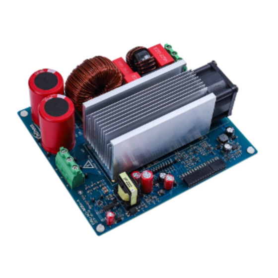
EVAL-M3-IM564 is an Evaluation board as part of the iMOTION™ Modular Application Design Kit. This power
board includes a PFC integrated 3-phase CIPOS™ Mini Intelligent Power Module (IPM) for motor drive
application. In combination with the control board equipped with the M3 30pin interface connector such as
EVAL-M3-102T, it features and demonstrates Infineon's CIPOS™ Mini IPM technology and Advanced Motion
Control Engine (MCE 2.0) technology for permanent magnet motors drive over the full speed range.
The inverter section has 600V of voltage and 20A of current rating, and the PFC section has 600V of voltage and
20A of current rating. It is optimized to major home appliances like air conditioners and low power motor dirve
application with high frequency switching operation of power factor correction.
This Evaluation board EVAL-M3-IM564 was developed to support customers during their first steps designing
application with CIPOS™ Mini PFC integrated IPM IM564-X6D/IM564-X6DS and running any permanent magnet
motor via sensorless sinusoidal control.
Intended audience
This user manual is intended for all technical specialists who know motor control and high power electronics
converter and this board is intended to be used under laboratory conditions.
Table of contents
About this document ....................................................................................................................... 1
Table of contents ............................................................................................................................ 1
1
Safety precautions ................................................................................................................. 3
2
Introduction .......................................................................................................................... 4
3
EVAL-M3-IM564 main features ................................................................................................. 6
3.1
EVAL-M3- IM564 board specifications ..................................................................................................... 7
3.2
Pin assignment ........................................................................................................................................ 9
4
Getting Started with EVAL-M3-IM564 ....................................................................................... 11
4.1
Setting up the system............................................................................................................................ 11
4.2
iMOTION™ development tools and software ....................................................................................... 13
4.2.1
MCEWizard setup overview .............................................................................................................. 13
4.2.2
MCEDesigner setup overview .......................................................................................................... 15
5
Hardware description of EVAL-M3-IM564 ................................................................................. 18
5.1
Boost PFC section using CIPOS™ mini IPM ........................................................................................... 18
5.1.1
AC Voltage sensing and MCEWizard configuration ......................................................................... 18
5.1.2
Hardware Modification for AC Voltage sensing to work with IRMCF188 ........................................ 19
5.1.3
PFC External Current feedback configuration and calculation ...................................................... 20
5.1.4
PFC Overcurrent protection circuit and PFC Gatekill configuration .............................................. 21
User Manual
www.infineon.com
Please read the Important Notice and Warnings at the end of this document
page 1 of 45
Revision 1.0
2019-09-17
Advertisement
Table of Contents

Related Manuals for Infineon iMOTION EVAL-M3-IM564


Summary of Contents for Infineon iMOTION EVAL-M3-IM564
-
Page 1: Table Of Contents
In combination with the control board equipped with the M3 30pin interface connector such as EVAL-M3-102T, it features and demonstrates Infineon’s CIPOS™ Mini IPM technology and Advanced Motion Control Engine (MCE 2.0) technology for permanent magnet motors drive over the full speed range. - Page 2 EVAL-M3-IM564 User Manual iMOTION™ Modular Application Design Kit Table of contents Inverter section using CIPOS™ mini IPM ....................22 5.2.1 DC bus sensing and MCEWizard configuration ................23 5.2.2 Motor External Current feedback configuration and calculation ..........23 5.2.3 Inverter Overcurrent protection and Motor Gatekill configuration ..........25 Thermistor/NTC Characteristics and protection calculation ..............
-
Page 3: Safety Precautions
EVAL-M3-IM564 User Manual iMOTION™ Modular Application Design Kit Safety precautions Safety precautions In addition to the precautions listed throughout this manual, please read and understand the following statements regarding hazards associated with development systems. Table 1 Precautions Attention: The ground potential of the EVAL-M3-IM564 system is biased to a negative DC bus voltage potential. -
Page 4: Introduction
The EVAL-M3-IM564 Evaluation board is available through regular Infineon distribution partners as well as on Infineon's website. The features of this board are described in the main features chapter of this document, whereas the remaining paragraphs provide information to enable the customers to copy, modify and qualify the design for production according to their own specific requirements. - Page 5 EVAL-M3-IM564 User Manual iMOTION™ Modular Application Design Kit Introduction Evaluation boards are not subject to the same procedures as regular products regarding Returned Material Analysis (RMA), Process Change Notification (PCN) and Product Discontinuation (PD). Evaluation boards are intended to be used under laboratory conditions by technical specialists only. User Manual 5 of 45 Revision 1.0...
-
Page 6: Eval-M3-Im564 Main Features
EVAL-M3-IM564 is an Evaluation board for motor drive applications with single phase PFC integrated 3 phase IPM. Combined in a kit with one of the available MADK control board options, it demonstrates Infineon’s motion control IC and IPM technology for motor drives with single phase PFC. -
Page 7: Eval-M3- Im564 Board Specifications
EVAL-M3-IM564 User Manual iMOTION™ Modular Application Design Kit EVAL-M3-IM564 main features EVAL-M3- IM564 board specifications Table 2 depicts the important specifications of the Evaluation board EVAL-M3-IM564. Table 2 EVAL-M3-IM564 board specifications Parameters Values Conditions / comments Input Voltage 165 - 265 V lower AC input, less motor power output Input current 9.6 A... - Page 8 EVAL-M3-IM564 User Manual iMOTION™ Modular Application Design Kit EVAL-M3-IM564 main features Figure 2 points out the functional groups on the top side of the EVAL-M3-IM564 Evaluation board. 1. J1 - AC Input connector 2. Relay, NTC and Fuse 3. PFC gate drive and PFC overcurrent protection circuits 4.
-
Page 9: Pin Assignment
EVAL-M3-IM564 User Manual iMOTION™ Modular Application Design Kit EVAL-M3-IM564 main features Figure 3 points out the functional groups on the bottom side of the EVAL-M3-IM564 Evaluation board. 11. CIPOS™ mini IPM U4 12. Rectifier bridge U1 Figure 3 Functional groups of the EVAL-M3-IM564 Evaluation board’s bottom side Pin assignment General information about the connectors of the EVAL-M3-IM564 Evaluation board is reported. - Page 10 EVAL-M3-IM564 User Manual iMOTION™ Modular Application Design Kit EVAL-M3-IM564 main features Table 5 provides the pin assignments of the 30 pins iMOTION™ MADK-M3 interface connector J3. This connector is the interface to the controller board. Table 5 J3 - iMOTION™ MADK-M3 30 pin interface connector for controller board Name Pin Name Connectors PWMUH...
-
Page 11: Getting Started With Eval-M3-Im564
3. Get the latest “IMC102T-F064 MCE Software Package” available on www.infineon.com/imotion-software web page. (Infineon iMOTION™ control IC IMC102T-F064 is used for control board EVAL-M3-102T). 4. Connect motor phase outputs to the motor. 5. Use MCEWizard to enter the motor and Evaluation board hardware parameters and click button “Export to Designer file (.txt)”... - Page 12 EVAL-M3-IM564 User Manual iMOTION™ Modular Application Design Kit Getting Started with EVAL-M3-IM564 7. Open MCEDesigner and open MCEDesigner default configuration file (.irc) for IMC102T devices (IMC102T_xx.irc) by clicking “File” menu and select “Open” in the pull down list. 8. Import system drive parameters file (generated in step 5) into MCEDesigner by clicking “File” > “Import Drive Parameters”.
-
Page 13: Imotion™ Development Tools And Software
“Welcome Page” for MCEWizard, where the MADK control board or power board can be selected through the pull-down list. Infineon keeps releasing new MADK controller and power boards. Therefore, it could happen that some of the newest power boards are not pre-configured in the MCEWizard tool and cannot be selected through the pull-down menu. - Page 14 EVAL-M3-IM564 User Manual iMOTION™ Modular Application Design Kit Getting Started with EVAL-M3-IM564 Table 6 MCEWizard setup overview table Page Parameter Value Comment Welcome Page Power Board selecting MADK power board name If no, select similar power board to modify Options Page Motor 1 Shunt Configuration Single Shunt Question 5...
-
Page 15: Mcedesigner Setup Overview
EVAL-M3-IM564 User Manual iMOTION™ Modular Application Design Kit Getting Started with EVAL-M3-IM564 Click “Calculate” button and “Export to Designer File (.txt)” button to save the parameter file which will be used by the MCEDesigner in the next steps. 4.2.2 MCEDesigner setup overview After installing MCEDesigner installer, there is a shortcut for MCEDesigner on Windows desktop. - Page 16 EVAL-M3-IM564 User Manual iMOTION™ Modular Application Design Kit Getting Started with EVAL-M3-IM564 Figure 8 “Program IMC Controller” pop-up window After Drive System Parameter file has been programmed into IMC102 controller, and the motor drive system is powered, the MCEDesigner can be used to start/stop the motor, display motor current traces, change the motor speeds, modify drive parameters and many other functions.
- Page 17 Getting Started with EVAL-M3-IM564 Figure 9 Program Firmware and Parameter in “Program IMC Controller” pop-up window All latest firmware file for different type of iMOTION control ICs are available for download via Infineon iMOTION website (http://www.infineon.com/imotion-software). User Manual 17 of 45 Revision 1.0...
-
Page 18: Hardware Description Of Eval-M3-Im564
EVAL-M3-IM564 User Manual iMOTION™ Modular Application Design Kit Hardware description of EVAL-M3-IM564 Hardware description of EVAL-M3-IM564 To meet individual customer requirements and make the EVAL-M3-IM564 Evaluation board a basis for development or modification, all necessary technical data like schematics, layout and components are included in this chapter. -
Page 19: Hardware Modification For Ac Voltage Sensing To Work With Irmcf188
EVAL-M3-IM564 User Manual iMOTION™ Modular Application Design Kit Hardware description of EVAL-M3-IM564 There are two AC voltage sensing modes in MCEWizard, differential mode and single-ended as shown in Figure 12. Please select differential mode for the combination between EVAL-M3-IM564 and EVAL-M3-102T. Figure 12 Vac Sensing Method configuration for EVAL-M3-102T and EVAL-M3-IM564 The high side resistors R1 and R2 or R9 and R10 for the AC voltage sensing resistor divider on the power board... -
Page 20: Pfc External Current Feedback Configuration And Calculation
EVAL-M3-IM564 User Manual iMOTION™ Modular Application Design Kit Hardware description of EVAL-M3-IM564 IRMCF188, AC Voltage sensing should be behind the rectifier bridge D1. To work with control board EVAL-M3- 188 or IRMCF188, power board EVAL-M3-IM564 should be modified by assembling 1MΩ AC Voltage sensing resistors R2A and R10A and removing the resistors R2 and R10. -
Page 21: Pfc Overcurrent Protection Circuit And Pfc Gatekill Configuration
EVAL-M3-IM564 User Manual iMOTION™ Modular Application Design Kit Hardware description of EVAL-M3-IM564 5.1.4 PFC Overcurrent protection circuit and PFC Gatekill configuration PFC protection circuit for EVAL-M3-IM564 as shown in Figure 16, but the left side of RS3 is negative. If the bus current Ibus is larger than the setting value, the output VFO of U1 will be trigger low and be active. -
Page 22: Inverter Section Using Cipos™ Mini Ipm
EVAL-M3-IM564 User Manual iMOTION™ Modular Application Design Kit Hardware description of EVAL-M3-IM564 The PFC’s overcurrent protection circuit on the control board EVAL-M3-102T is shown in Figure 15 and Figure 17. The I equal to 42.73A for the combination between EVAL-M3-102T and EVAL-M3-IM564 only. PFCTRIP_Peak The calculation formula is as follows, −... -
Page 23: Dc Bus Sensing And Mcewizard Configuration
EVAL-M3-IM564 User Manual iMOTION™ Modular Application Design Kit Hardware description of EVAL-M3-IM564 5.2.1 DC bus sensing and MCEWizard configuration Pin 14 and pin 26 of connector J3 provide access to the DC-link voltage DCBsense. Three possible feedback cases are associated with these pins. Figure 19 provides the DC bus sense resistor details. By default, the resistor R21 is not mounted on EVAL-M3-IM564. - Page 24 EVAL-M3-IM564 User Manual iMOTION™ Modular Application Design Kit Hardware description of EVAL-M3-IM564 Figure 21 Current shunt feedback and sample timing for EVAL-M3-102T The External Amplifier Gain circuit can be found in the schematics or User Manual for the control board (For example, EVAL-M3-102T see Figure 22).
-
Page 25: Inverter Overcurrent Protection And Motor Gatekill Configuration
EVAL-M3-IM564 User Manual iMOTION™ Modular Application Design Kit Hardware description of EVAL-M3-IM564 Figure 23 Current feedback configuration in MCEWizard for EVAL-M3-102T and EVAL-M3-IM564 5.2.3 Inverter Overcurrent protection and Motor Gatekill configuration Figure 24 displays the overcurrent protection circuitry. The current sensing signal I_Shunt is connected to ITRIP via the resistor R39, and ITRIP is filtered through capacitor C38. -
Page 26: Thermistor/Ntc Characteristics And Protection Calculation
EVAL-M3-IM564 User Manual iMOTION™ Modular Application Design Kit Hardware description of EVAL-M3-IM564 But please note that, if select comparator for Gatekill Input Source, the external Gatekill signal will be not used. And the current sensing signal I_Shunt will be compared by the internal comparator with the “Gatekill Comparator Reference”... -
Page 27: Overtemperature Hardware Protection Circuit
EVAL-M3-IM564 User Manual iMOTION™ Modular Application Design Kit Hardware description of EVAL-M3-IM564 The VFO pin of CIPOS™-Modules provides direct access to the NTC, which is referenced to VSS. An external pull- up resistor connected to +3.3V ensures that the resulting voltage can be directly connected to the microcontroller. -
Page 28: System Thermal Resistance Testing
EVAL-M3-IM564 User Manual iMOTION™ Modular Application Design Kit Hardware description of EVAL-M3-IM564 ∗ ∗ ∗ If the setting temperature is 100°C, the shutdown value should be 2.75V. If the setting temperature is 85°C, the shutdown value should be 2.87V. Figure 28 External temperature sense input configuration in MCEWizard System thermal resistance testing 5.4.1... -
Page 29: System Power Output Capability
EVAL-M3-IM564 User Manual iMOTION™ Modular Application Design Kit Hardware description of EVAL-M3-IM564 Thermal resistance between junction to ambient R is divided into 2 parts as following formular, thermal thJA resistance between junction to case R and thermal resistace between case to ambient R thJC thCA ∆... -
Page 30: Auxiliary Power Supply
EVAL-M3-IM564 User Manual iMOTION™ Modular Application Design Kit Hardware description of EVAL-M3-IM564 With the MADK output power increasing, IPM DCB PFC test point and IGBT test point temperature are monitored, final test result are shown as Figure 31. Auxiliary power supply Figure 32 depicts the schematic of the auxiliary power supply for the EVAL-M3-IM564 board. - Page 31 EVAL-M3-IM564 User Manual iMOTION™ Modular Application Design Kit Hardware description of EVAL-M3-IM564 Figure 33 PFC Section Schematics for EVAL-M3- IM564 User Manual 31 of 45 Revision 1.0 2019-09-17...
- Page 32 EVAL-M3-IM564 User Manual iMOTION™ Modular Application Design Kit Hardware description of EVAL-M3-IM564 The Inverter setion schematic for EVAL-M3- IM564 is provided in Figure 34. Figure 34 Inverter Section Schematics for EVAL-M3- IM564 User Manual 32 of 45 Revision 1.0 2019-09-17...
- Page 33 EVAL-M3-IM564 User Manual iMOTION™ Modular Application Design Kit Hardware description of EVAL-M3-IM564 The Auxiliary Power Supply setion schematic for EVAL-M3- IM564 is provided in Figure 35. Figure 35 Auxiliary Power Supply Section Schematics for EVAL-M3- IM564 User Manual 33 of 45 Revision 1.0 2019-09-17...
-
Page 34: Pcb Layout For Eval-M3- Im564
EVAL-M3-IM564 User Manual iMOTION™ Modular Application Design Kit Hardware description of EVAL-M3-IM564 PCB Layout for EVAL-M3- IM564 The layout of this board can be used for different voltage or power classes. The PCB has two electrical layers with 35µm copper by default and its size is 148 mm × 165 mm. The PCB board thickness is 1.6mm. Get in contact with our technical support team to get more detailed information and the latest Gerber-files. - Page 35 EVAL-M3-IM564 User Manual iMOTION™ Modular Application Design Kit Hardware description of EVAL-M3-IM564 Figure 37 depicts the bottom assembly print of the Evaluation board. Figure 37 Bottom assembly print of the EVAL-M3-IM564 Evaluation board User Manual 35 of 45 Revision 1.0 2019-09-17...
- Page 36 EVAL-M3-IM564 User Manual iMOTION™ Modular Application Design Kit Hardware description of EVAL-M3-IM564 The top layer routing of the PCB is provided in Figure 38. Figure 38 Top layer routing of the EVAL-M3-IM564 User Manual 36 of 45 Revision 1.0 2019-09-17...
- Page 37 EVAL-M3-IM564 User Manual iMOTION™ Modular Application Design Kit Hardware description of EVAL-M3-IM564 Figure 39 illustrates the bottom layer routing of the PCB. Figure 39 Bottom layer routing of the EVAL-M3-IM564 User Manual 37 of 45 Revision 1.0 2019-09-17...
-
Page 38: Bill Of Material
EVAL-M3-IM564 User Manual iMOTION™ Modular Application Design Kit Bill of material Bill of material Table 8 provides the complete bill of materials for the EVAL-M3-IM564. Table 8 Bill of materials Qty Part description Designator Part number Manufacturer C1, C18, C1210C104KBRAC78 CAP CER 0.1UF 630V X7R 1210 C57, C58, KEMET... - Page 39 Wurth Electronics Inc. BRIDGE RECT 1PHASE 1200V 25A GBJ2512 Diodes Incorporated DIODE SCHOTTKY 30V 200MA SC79- D2, D3, D9, BAT5402VH6327XTS Infineon Technologies DIODE SCHOTTKY 20V 1A SOD123L MBR120ESFT1G ON Semiconductor DIODE SCHOTTKY 150V 2A DO15 MBR2150VGTR-E1 Diodes Incorporated DIODE GEN PURP 1KV 1A SMA...
- Page 40 EVAL-M3-IM564 User Manual iMOTION™ Modular Application Design Kit Bill of material Qty Part description Designator Part number Manufacturer R3, R28, R45, RC0603FR-0710KL Yageo R17, R50, RES SMD 10kΩ 1% 1/10W 0603 RT0603BRD073KL Yageo RES SMD 3K OHM 0.1% 1/10W 0603 R5, R29, RT0603DRD071KL Yageo...
- Page 41 EVAL-M3-IM564 User Manual iMOTION™ Modular Application Design Kit Bill of material Qty Part description Designator Part number Manufacturer RES SMD 2.2 OHM 5% 1/8W 0805 R24, R52, RC0805JR-072R2L Yageo RES SMD 51 OHM 5% 1/4W 1206 R27, R55 RC1206JR-0751RL Yageo RES SMD 68K OHM 5% 1/4W 1206 RC1206JR-0768KL Yageo...
- Page 42 U1, U8 LMV331IDBV Texas Instruments IC DRIVER LOW SIDE 1.5A SOT23-5 IRS44273LTRPBF Diodes Incorporated IC REG LINEAR 3.3V 1A SOT223-4 IFX1117MEV33HTMA Infineon Technologies IC CTLR QUASI-RES 12SOIC ICE5QR4770AGXUMA Infineon Technologies OPTOISOLATOR 5KV TRANSISTOR FOD817BSD ON Semiconductor 4SMD IC VREF SHUNT ADJ SOT23-3...
-
Page 43: Reference
AN2018-02 EVAL-M3-102T User manual MCEWizard User Guide MCEDesigner User Guide Note: All listed reference materials are available for download on Infineon’s website www.infineon.com/. All the iMOTION MADK Evaluation board’s User Manuals are available at www.infineon.com/MADK All the CIPOS™ IPM’s Datasheets and documents are available at www.infineon.com/IPM. -
Page 44: Revision History
EVAL-M3-IM564 User Manual iMOTION™ Modular Application Design Kit Reference Revision history Document Date of release Description of changes version 2019-09-17 First release User Manual 44 of 45 Revision 1.0 2019-09-17... - Page 45 Infineon Technologies hereby disclaims dangerous substances. For information on the types © 2019 Infineon Technologies AG. any and all warranties and liabilities of any kind in question please contact your nearest Infineon All Rights Reserved. (including without limitation warranties of non- Technologies office.
Need help?
Do you have a question about the iMOTION EVAL-M3-IM564 and is the answer not in the manual?
Questions and answers