Table of Contents
Advertisement
Quick Links
Advertisement
Table of Contents

Subscribe to Our Youtube Channel
Related Manuals for Teledyne T3HVD


Summary of Contents for Teledyne T3HVD
- Page 1 T3HVD Voltage Probe Manual High Voltage Differential Probes...
-
Page 2: Table Of Contents
Warranty ......................17 © 2021 Teledyne LeCroy, Inc. All rights reserved. Teledyne Test Tools is a trademark of Teledyne LeCroy, Inc. Other product or brand names are trademarks or requested trademarks of their respective holders. Information in this publication supersedes all earlier versions. Specifications are subject to change without notice. -
Page 3: Safety Terms And Symbols
Safety To maintain the probe in a correct and safe condition, observe generally accepted safety procedures in addition to the precautions specified in this section. The overall safety of any system incorporating this product is the responsibility of the assembler of the system. Symbols These symbols appear on the probe and accessories or in this manual to alert you to important safety considerations. - Page 4 Do not remove the probe's casing. Touching exposed connections may result in electric shock or burn. To prevent damage to the equipment: CAUTION. Use only as specified. Use of the probe and/or the equipment it is connected to in a manner other than specified may impair the protection mechanisms.
-
Page 5: Voltage Vs. Frequency Derating And Burn Limit
Voltage vs. Frequency Derating and Burn Limit The maximum input voltage curve (solid line) shows the maximum voltage that can be applied to the probe inputs without risking damage to the probe. The lower Burn Limit curve (dashed line) shows the maximum voltage that can be applied to the probe inputs while the operator is handling the inputs. - Page 6 T3HVD7000-100 Derating and Burn Limit 2500 2000 1500 1000 1 kHz 10 kHz 100 kHz 1 MHz 10 MHz 100 MHz Vmax Frequecny Burn Limit Page 4...
-
Page 7: Voltage Derating For Combined Probe And Accessories
The voltage and CAT rating of the probe are derated to the values in the table above when used with the corresponding accessory. WARNING. While all probes may be used with the T3HVD accessories (alligator clips, pincer clips, etc.), the voltage and CAT ratings of the probe are derated to the values in the table above when used with the corresponding accessory. -
Page 8: Product Overview
7000 V peak, 100 MHz Teledyne Test Tools new T3HVD range of high voltage differential probes are wide bandwidth active differential voltage probes, featuring models with bandwidths up to 200 MHz bandwidth, voltages up to + 7000V (DC + Pk AC), fast and accurate waveform capture, measurement accuracy of + 2% and low test circuit loading. -
Page 9: Product Description
T3HVD Product Description Measurement voltage input leads Maximum measurable differential voltage Maximum input voltage to earth Overload indicator Attenuation / range Indicator Attenuation / range switch Bandwidth indicator Bandwidth limit switch Audible range overload indicator Audible range overload on / off switch... -
Page 10: Adjusting The Probe Offset
BNC to BNC cable. If the oscilloscope input impedance is set to 50Ω then the measured oscilloscope voltage will be incorrect. Power for the T3HVD probes can be supplied from the included USB power supply or from a USB socket ●... -
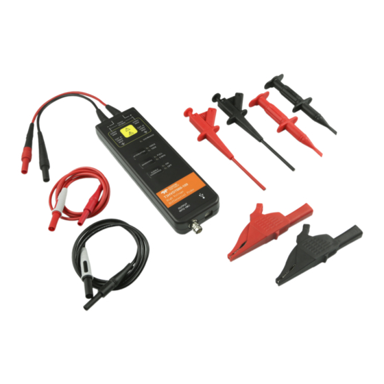
Page 11: Supplied Accessories
1m T3HVD BNC to BNC Cable x 1 1.5m T3HVD USB A to B Power Cable x 1 The T3HVD probe kit also includes a USB power supply (not pictured) that the T3HVD USB A to B Power ● Cable can connect to. -
Page 12: Specifications
Alligator Clips CAT III 1000V / CAT IV 600V Pincer Clips x 2 CAT III 1000V Hook Clips x 2 CAT III 1000V Extender Leads x 2 1 m, CAT III 1000V BNC to BNC Cable x 1 USB Power Cable x 1 1.5 m Power Adapter x 1 USB 5V / 1A... -
Page 13: Performance Verification
Connect power to the probe and allow 30 minutes warm up time. ● DC Accuracy Test Connect the T3HVD probe BNC output to the Digital Multimeter input using the Male BNC to Binding ● Posts adapter. Connect the male BNC connector to the T3HVD female BNC output. Connect the Multimeter test leads to the binding posts. -
Page 14: Rise Time Test
< 3.5ns 1000 x DC Common Mode Ratio Test Set the T3HVD probe to its lower voltage range and connect the probe inputs to the DC voltage source or ● calibrator. Set the multimeter to DC Volts, connect the multimeter cables together, then auto-zero the multimeter. -
Page 15: Test Record Form
Test Record Form Product Serial Number: Test Temperature: Test Date: Test Humidity: Test Model: Lower Limit Test result Upper Limit 50 x 98 mV 102 mV T3HVD1500-70 500 x 98 mV 102 mV 50 x 98 mV 102 mV DC Accuracy T3HVD1500-200 500 x 98 mV... -
Page 16: Certifications
Certifications Teledyne LeCroy certifies compliance to the following standards as of the date of publication. As standards evolve, these may no longer be current. See the Declaration of Conformity shipped with your product for current certifications. EMC Compliance EC Declaration of Conformity - EMC The probe meets the intent of EC Directive 2014/30/EU for Electromagnetic Compatibility. -
Page 17: Safety Compliance
Many countries prohibit the disposal of waste electronic equipment in standard waste receptacles. For more information about proper disposal and recycling of your Teledyne LeCroy product, visit teledynelecroy.com/recycle. Restriction of Hazardous Substances (RoHS) The product and its accessories conform to the 2011/65/EU RoHS2 Directive inclusive of any further amendments or modifications of said Directive. - Page 18 CHINA RoHS 2 Unless otherwise specified, all the materials and processes are compliant with the latest requirements of China RoHS 2. The hazardous substances contained in the instrument are disclosed in accordance with the standards SJ/T 11364-2014 (Marking for the restricted use of hazardous substances in electronic and electrical products) and GB/T 26572-2011 (Requirements on concentration limits for certain restricted substances in electrical and electronic products).
-
Page 19: Warranty
Spare parts, replacement parts and repairs are warranted for 90 days. In exercising its warranty, Teledyne LeCroy, at its option, will either repair or replace any assembly returned within its warranty period to the Customer Service Department or an authorized service center. - Page 20 © 2020 Teledyne Test Tools is a brand and trademark of Teledyne LeCroyInc. All rights reserved.Specifications,prices,availability and deliverysubject to change without notice. Product brand or brand names are trademarks or requested trademarks of their respective holders. T3 stands for Teledyne Test Tools.
Need help?
Do you have a question about the T3HVD and is the answer not in the manual?
Questions and answers