
Related Manuals for Graf oneAdvanced


Summary of Contents for Graf oneAdvanced
- Page 1 O P E R A T I O N M A N U A L Startup | Operation | Maintenance oneAdvanced – KLcontrol...
- Page 2 Read carefully these instructions before installation, assembly, and startup. Keep these in a safe place for future reference. Instructions for startup, operation, and maintenance Issued for GRAF oneAdvanced wastewater treatment plant Control unit KLcontrol.M EAN no. 4023122286325 Date issued 30/01/2023...
-
Page 3: Table Of Contents
3.2.1 Layout of oneAdvanced 3–9 PE ......................15 3.2.2 Layout of oneAdvanced 10–14 PE ....................... 16 3.2.3 3.2.2 Layout of oneAdvanced 16–1000 PE ..................17 3.2.4 Function of the SBR plant ........................18 Control and machine cabinet ......................24 3.3.1 Technical setup............................ - Page 4 7.4.1 Sludge measurements on oneAdvanced 3–9 PU (one-tank systems) ..........55 7.4.2 Sludge measurements on oneAdvanced larger than 10 PE (with preliminary cleaning / sludge reservoir) ............................. 57 Sludge must be removed by a specialist only ................... 57 Service menu for authorised specialist ..................59 Menu overview ..........................
- Page 5 Contents 11.1 Power failure ............................. 97 11.2 events in tabular form ........................98 11.2.1 Information messages ......................... 99 11.2.2 Fault messages ..........................100 11.2.3 Error messages ..........................101 11.3 Unusual water levels– remedying a fault ..................103 11.4 Possible faults on step motor valves ....................104 11.5 Water quality ...........................
-
Page 6: About These Instructions
Copyright These instructions for use contain copyrighted information and figures. Otto Graf GmbH Kun- ststofferzeugnisse reserves all rights. No part of these instructions for use may be duplicated, reproduced, used for other purposes, or translated into any language without the prior, explicit consent issued in writing by Otto Graf GmbH Kunststofferzeugnisse. -
Page 7: Typeface Conventions
1. About these instructions 1.1 Typeface conventions These instructions make use of the following typeface conventions. Format Meaning Italic text This refers the reader to other contents in this document, other sections of the instructions for use, or additional information. Digitised media (e.g. -
Page 8: Safety
2. Safety Safety Despite all safety precautions, the plant may nevertheless pose some degree of residual risk, particularly when handled incorrectly or negligently. To protect yourself and others from all dan- ger and to prevent damage and pollution as a result of incorrect handling, therefore, please read and follow the safety and other instructions in both this and the other sections making up the in- structions for use. -
Page 9: Intended Use
2. Safety This highlights potential risks from electricity. This highlights a potential risk of falling. This highlights potential risks from hot surfaces. This highlights potential risks from optical radiation. 2.1.2 Intended use The SBR plant has been designed to channel domestic wastewater from private homes. Domes- tic wastewater contains faeces and other substances found in bath, washing, sink, and mop wa- ter such as soap, detergent, and food scraps. -
Page 10: Safety Instructions For The Operator
2. Safety 2.2 Safety instructions for the operator The operator of the plant is responsible for its correct installation and operation. He is also re- sponsible for ensuring adherence to the safety and other instructions in this section, but also to the laws, standards, rules, and regulations pertaining to the plant’s site. -
Page 11: General Safety Measures
2. Safety 2.3 General safety measures Keep tank covers closed at all times. Never leave open tank covers unattended. Tank covers may be opened for inspection and maintenance purposes only. There is a danger of persons or animals falling into the tank. This may result in serious injury or drowning. -
Page 12: Safety Measures For Inspection And Maintenance
2. Safety 2.4 Safety measures for inspection and maintenance Do not consume any food or drink when operating or working at or on the plant. Edibles coming into contact with microbes may carry and cause infection. Shutting down the plant’s installations and equipment. Equipment may start to operate unexpectedly. - Page 13 2. Safety Increase access safety and provide an escape route Use only suitable equipment, e.g. ladder, to access the tank. Make sure that the escape route remains unobstructed. 2.4.1.1 In the event of an accident in the tank If the accident victim is unconscious, do not under any circumstances attempt to climb in to his rescue.
-
Page 14: General
Should you encounter a fault, these details will enable our staff to find a remedy faster. Your plant’s specifications can be found on the type plate. This type plate is affixed to the exter- nal housing of internal switch cabinets and inside external switch cabinets. Figure 1: Example oneAdvanced type plate 14 / 137... -
Page 15: Layout And Functions
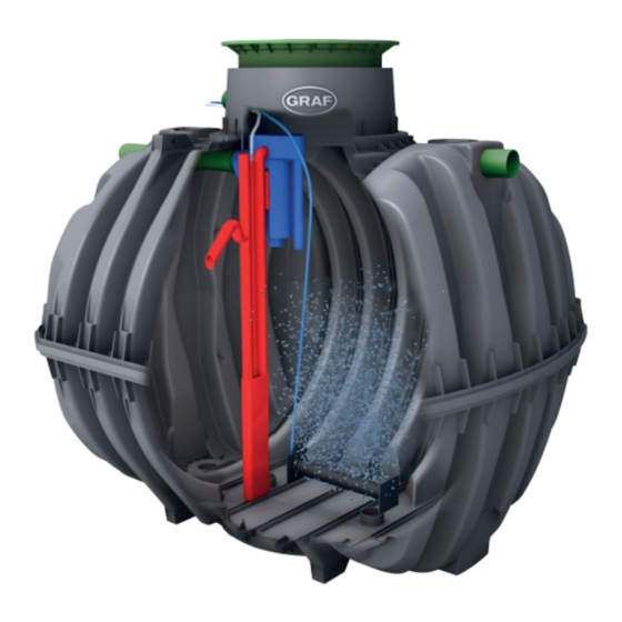
Sampling unit Outlet DN110 Inlet DN110 Clear water lifter Figure 2: oneAdvanced 3–9 PE in a Carat tank (example) The tank houses: a scum guard two membrane pipe aerators outflow lifter in the form of a mammoth pump with its own air supply... -
Page 16: Layout Of Oneadvanced 10-14 Pe
Sludge reservoir / buffer SBR reactor Figure 3: oneAdvanced 10–14 PE in a Carat tank (example) The tank is split into two areas by a scum guard: a sludge reservoir and buffer in the inlet area and an SBR reactor in the outlet area. -
Page 17: Layout Of Oneadvanced 16-1000 Pe
3. General 3.2.3 3.2.2 Layout of oneAdvanced 16–1000 PE DN110 DN110 DN110 Sludge return Membrane plate aerator Feed lifter Sampling unit Clear water lifter DN110 DN110 DN110 SBR reactor SBR reactor Sludge reservoir / buffer Figure 4: Example multi tank system in two Carat tanks The wastewater treatment plant is made up of several tanks. -
Page 18: Function Of The Sbr Plant
3.2.4 Function of the SBR plant oneAdvanced is a fully biological wastewater treatment system, which functions on the princi- ple of the SBR process (aeration system in retention process). This fully biological treatment takes place with aerated sludge. Aerated sludge basically consists... - Page 19 2 cycles are undertaken a day. The maintenance company can individually adapt the switching times. 3.2.4.2 Process flow of oneAdvanced larger than 10 PE The process is a series of 5 steps undertaken in turn and repeated several times a day (usually four times).
- Page 20 3. General Step 2: Aeration In this step, the wastewater is aerated and mixed. Membrane pipe or plate aerators fitted on the base of the chamber aerate the wastewater. The plant's aeration equipment is supplied with ambient air by a control cabinet installed separately. An air compressor pro- duces the compressed air needed.
- Page 21 3. General Step 5: Sludge return In this phase, the excess activated sludge at the bottom is pumped by an air lift pump from the SBR reactor chamber to the sludge reservoir chamber, where it is stored. Duration: 1–2 min At the end of this treatment cycle, the plant pauses for the time remaining until the next cycle start time (about 1–10 minutes).
- Page 22 All GRAF treatment systems can be used for nitrification and denitrification. No additional com- ponentry is needed. Solely the controller’s cleaning program must be configured accordingly.
- Page 23 3. General In this event, a dosing pump in the switch cabinet conveys automatically a specific quantity of special nutrient solution directly into the aeration basin. This dose can be adjusted at the control- ler. Carbon dosing serves to maintain the stability of the aerated sludge quantity in the system, even when there is only a sporadic or very low supply of wastewate.
-
Page 24: Control And Machine Cabinet
3–28 PE) or powder-coated metal (used for wastewater treatment plants for 28 PE or more). The internal PP switch cabinet can be fitted in a GRAF external switch cabinet M, and in this manner used out of doors as well. -
Page 25: Technical Setup
3. General 3.3.1 Technical setup The main components of the controller are: Internal cabinet hood Bearer Type plate compressor Control unit Air distributor External cabinet hood External cabinet base section Empty pipe aperture for external cabinet Power strip 230 V Dosing pump (optional) Chemicals tank 37 l (optional) Chemicals tank vent (optional) -
Page 26: Siting
3. General 3.3.2 Siting The control unit must not be fitted or activated in environments with potential explosive atmos- pheres or in places where there are flammable materials. Sparks in such environments may cause an explosion or fire and this may result in physical injuries or even death. Ensure that the machine cabinet is not installed above or in the direct vicinity of water vessels. - Page 27 3. General Electrical equipment connected to the mains may be damaged during a storm. We would recom- mend fitting surge protection in the building to protect against this. The connection cable must be laid such that it does not represent a tripping hazard. 27 / 137...
-
Page 28: The Wastewater Treatment System's Control Unit
4. The wastewater treatment system’s control unit The wastewater treatment system’s control unit The plant is controlled at the operating unit on the controller’s face side. The controller is used to configure the operating parameters, view the operating statuses, query the plant parameters, and program the operating times (this last by a specialist). -
Page 29: Operating Unit
4. The wastewater treatment system’s control unit 4.1 Operating unit The operating unit consists of a USB port (A), a display (B), a cursor pad (C), and a status LED (D). Figure 8: KLcontrol.M operating unit USB port (A) The USB port accepts a USB stick (see also Subsection 4.4.7 on page 41). Display (B) Menu navigation is presented on a colour display. -
Page 30: Display Information And Menu Navigation
4. The wastewater treatment system’s control unit opens menu item opens config parameters or view confirms settings Status LED (D) This LED indicates the present status as one of the four following colours: green: Auto mode. Everything OK. blue: manual mode yellow: Warning. -
Page 31: Status Bar Symbols
4. The wastewater treatment system’s control unit 4.2.1 Status bar symbols The controller status appears in the status bar. The displayed symbols also serve as navigation aids through the menu structure. The following symbols are provided: Symbol Description Auto mode: The controller is in auto mode. Manual mode: Auto mode has been suspended. - Page 32 4. The wastewater treatment system’s control unit Service: This is the access area for specialists. USB: This is used to update the software, save/load configurations, and save logging data. 32 / 137...
-
Page 33: Operating The Controller
4. The wastewater treatment system’s control unit 4.3 Operating the controller 4.3.1 Menu navigation 1. Using the cursor keys [◄] [►], select the menu you need. 2. Press [OK] to open the menu. 3. Using the cursor keys [▼] [▲], select the menu item you need. 4. -
Page 34: Operator Menu
4. The wastewater treatment system’s control unit 4.4 Operator menu 4.4.1 Information menu – show operating hours, settings, sensor values Information Operating hours tot. This presents the total operating hours generated by the out- puts. Outputs that have not generated operating hours are hidden. The remaining runtime of the UV lamp is given in brackets. -
Page 35: Events Menu - Show Events
4. The wastewater treatment system’s control unit Show sensor values This presents the measurements returned by the pressure and temperature sensors. Pressure sensor mbar Pressure sensor mbar Temperature sen- °C sor: Show switches This presents the status of switching contacts (e.g. for float switches and contactors) X12.9 ON/OFF... -
Page 36: Mode Menu
4. The wastewater treatment system’s control unit 4.4.3 Mode menu This switches between auto and manual mode. Operation Mode Switch between auto and manual mode. All assigned outputs are listed. In manual mode, each output can be switched ON and OFF. Comp. - Page 37 4. The wastewater treatment system’s control unit 6. To revert to auto mode, select the Mode menu with the cursor keys [▼] [▲] and confirm “Auto” with [OK]. When auto mode is active, the icon appears in the symbol bar. The status LED lights up green.
-
Page 38: Times/Date Menu - Set Date, Clock, Holiday Period
4. The wastewater treatment system’s control unit 4.4.4 Times/date menu – set date, clock, holiday period Times/date Setting date + clock This sets the current date and clock time. Set the start and end dates of the holiday period. Set holiday period The holiday period then starts at midnight on the entered starting date and ends at 11:59 pm on the entered end date. -
Page 39: Settings Menu - Languages, Buzzer, Display Settings
4. The wastewater treatment system’s control unit 4.4.5 Settings menu – languages, buzzer, display settings Settings Language Select your language for the menus. Buzzer Settings for the acoustic alarm. Buzzer test ON/OFF Test acoustic alarm. The buzzer emits an acoustic signal. -
Page 40: Service Menu - Access For Specialists
4. The wastewater treatment system’s control unit 4.4.6 Service menu – access for specialists The service level can be enabled when a service code is entered. When service mode is active, the icon appears. Service mode lets users toggle between ser- vice and operator mode without their having to reenter the code. -
Page 41: Usb Menu - Software Update, Maintenance Manual
4. The wastewater treatment system’s control unit 4.4.7 USB menu – software update, maintenance manual The control unit’s face side presents a USB port that can take a storage medium. This USB port lets you: update software save/load a configuration save logging data save a maintenance manual Software update... - Page 42 4. The wastewater treatment system’s control unit 4.4.7.3 Updating the software The firmware may be updated only as instructed by the manufacturer (see the provided RE- ADME file). Before updating the microcontroller’s firmware, you will first need a USB memory stick contain- ing the manufacturer’s original file.
-
Page 43: Function Of The Power Cut Detector
4. The wastewater treatment system’s control unit 4.4.7.5 Recording All sensor values are saved every 5 minutes. The Operator menu provides a function to copy these logging data as a CSV file to a USB stick. There are two logging options: Record everything: All data from sensors, including pressure and temperature sensors, and all voltages and current measurements, T-steps, remaining times, and occurred events are logged to the USB memory at five-minute intervals. -
Page 44: Monitoring The Mains Voltage
4. The wastewater treatment system’s control unit 4.6 Monitoring the mains voltage The controller detects failed and excessive mains voltage. It detects an incorrect mains voltage by measuring the input voltage and comparing this with defined limits. The limits defined for an incorrect input voltage are <... -
Page 45: Initial Use
5. Initial use Initial use The wastewater treatment plant may be put into operation only when all of its components have been installed and connected to the full extent. Before commissioning, confirm that all electrical connections and air hoses have been fitted correctly and firmly! 5.1 Charging the tanks Before switching ON the plant, fill both chambers/tanks to the top with fresh water. -
Page 46: Function Tests
5. Initial use 5.4 Function tests Activate “manual” mode. In manual mode, tests can be performed on the lifters, aeration, and other connected consumers. The ventilation bubbles must be consistent and thorough. The air lift pumps operate only when the tank is sufficiently filled with water. For further details on these function tests, see Subsection 4.3 on page 33. -
Page 47: Startup Behaviour
5. Initial use 5.5 Startup behaviour In general, GRAF wastewater treatment plants require only a short startup phase. The startup phase is the time needed until the biotope generated in the wastewater treatment plant has be- come adequate to deliver and maintain the required discharge values. -
Page 48: Operating Instructions
Important: Faeces must not be allowed to enter the grease separator! The wastewater from commercial kitchens must be pretreated separately in an upstream grease separator. GRAF offers grease separators with nominal sizes up to 15. General recommendations for cleaning agents: Note the recommended doses on the packaging. - Page 49 6. Operating instructions substances which should not be disposed of via the sink or Why not: Where then: toilet: Does not break down Dustbin Chemicals Contaminate the wastewater Collection points Disinfectants Kill bacteria Do not use Paints Contaminate the wastewater Local collection point Photochemicals Contaminate the wastewater...
- Page 50 6. Operating instructions substances which should not be disposed of via the sink or Why not: Where then: toilet: Wallpaper paste Causes blockages Local collection point Textiles (e.g. nylon tights, cleaning cloths, handkerchiefs Block pipes, may paralyse a pump station Used textiles collection point etc.) Thinner...
-
Page 51: Operation And Maintenance
7. Operation and maintenance Operation and maintenance Almost all operating problems will result in the plant's cleaning capacity being impaired. This must be detected in good time and remedied immediately by the operator or a maintenance specialist. Before commencing work Prior to all inspection and maintenance work, familiarise yourself with the safety in- structions in Subsection 2. -
Page 52: General Specifications For Maintenance, Inspections, And Operation
7. Operation and maintenance 7.1 General specifications for maintenance, inspections, and operation The plant must remain switched ON at all times. The sole exception is during maintenance. If the plant is switched OFF for more than 24 hours, it will be unable to clean the wastewater properly, if at all. -
Page 53: Monthly Checks
7. Operation and maintenance 7.2.2 Monthly checks These monthly inspections must be documented. Visually check for any sludge leaks, clouding, or discoloration in the discharge Visual check for clogged supply and discharge routes Read operating hours counter for air compressor (total operating hours), aeration (valve 2), sludge return (valve 4), and if necessary any other units (when fitted), and note in operating log. -
Page 54: Yearly Checks
Sludge volume SV (< 700 ml/l); sludge volume > 700 ml/l must be removed For oneAdvanced larger than 10 PE (with preliminary cleaning / sludge reservoir): Sludge volume SV (< 400 ml/l); if > 400 ml/l, increase the duration of sludge removal... -
Page 55: Sludge Measurements
7.4.1 Sludge measurements on oneAdvanced 3–9 PU (one-tank systems) In oneAdvanced 3–9 EW there is only aerated sludge. Sludge removal is recommended when sludge volume exceeds 70%. A measurement cylinder is used to quantify the sludge (SV30 test). The measurements must... - Page 56 7. Operation and maintenance The measurement cylinders should be placed in a location free of vibrations and shielded from direct sunlight. easyOne plants generally operate with higher sludge contents, so there must be two sets of measurements here: Double quantification with two measurement cylinders: 1 x undiluted, 1 x diluted 1000 ml 30 min <...
-
Page 57: Sludge Measurements On Oneadvanced Larger Than 10 Pe (With Preliminary Cleaning / Sludge Reservoir)
Sludge measurements on oneAdvanced larger than 10 PE (with preliminary cleaning / sludge reservoir) There are various types of sludge in oneAdvanced wastewater treatment plants. Only the sludge in the preliminary cleaning need be removed. A distinction is drawn between floating and bottom sludge. - Page 58 7. Operation and maintenance Special measure for oneAdvanced 3–9 PU (single-tank systems with scum guard) 10 cm of water-sludge mixture should remain in the plant for maintaining the effectiveness of biological cleaning. Make sure there is no damage to the installations (membrane pipe...
-
Page 59: Service Menu For Authorised Specialist
8. Service menu for authorised specialist Service menu for authorised specialist Configuring the parameters in the Service menu requires specific knowhow. NOTE The Service menu is intended for specialists only and is code protected. Do not attempt to edit any of the settings here. This may otherwise prove detrimental to the plant’s correct and reliable operation. -
Page 60: Cycle Settings
10 PE, 4 valves, 4 cycles/day SBR One 3V: 3 valves, 2 cycles/day SBR One 2V: oneAdvanced no larger than 90 PE, 2 valves, 2 cycles/day SBR MAX 4V KLARO MAX large-scale plants, 4 valves SBR MAX 3V... -
Page 61: Overview Of Processes, Systems, And Discharge Classes
Demo Demo Dis- charge C/N/D/D+ C/N/D C/N/D C/N/D C/N/D class These instructions describe exclusively oneAdvanced plants with two (2V, oneAdvanced 3– 9 PE) and four valves (4V, oneAdvanced larger than 10 PE). These must therefore be selected. 61 / 137... - Page 62 8. Service menu for authorised specialist 8.2.1.1 Table layouts The table is divided into work steps, e.g. feed, and runtime calculations. Also the number of cleaning cycles per day can be edited. All work steps are made up of 3 T-steps. The first T-step of a work step is the total duration of the work step.
- Page 63 8. Service menu for authorised specialist NOTE Each cycle phase and each work step also shows the outputs used. Example: “Charging: X31, X16.V1” signals that, for charging purposes, output X31 for the compressor and X16.V1 for valve 1 are being addressed. Edits are possible in the menu “Assign outputs”. NOTE The T-settings may be edited in steps of one minute.
-
Page 64: Outputs
8. Service menu for authorised specialist 8.2.2 Outputs Prior to shipping, the output functions and assignments have been provided with the defaults listed in the following table. Additional components must be connected accordingly if the switch cabinet wiring is to continue complying with the circuit diagrams (clarity). Function KLcontrol.M Note... -
Page 65: Inputs
8. Service menu for authorised specialist 8.2.3 Inputs The KLcontrol.M control unit presents three inputs. These are not managed in the menu “Assign outputs”. Function KLcontrol.M Note Float switches X12.9 For their use as “canister empty” monitors, see Subsection 9.3; as flooding alarms, see Subsec- Float switches X12.11 tion 8.2.4)…... -
Page 66: Pressure Sensor
8. Service menu for authorised specialist 8.2.4 Pressure sensor The control units are fitted with two pressure sensors that can be used to measure the level and/or for monitoring the operating pressure. Before use, a specialist must first perform an on- site calibration (“service calibration”). - Page 67 This starts the service calibration for level measurements via the membrane pipe aerator. Same calibration process as with code 8 8 8 8 (see Subsection 9.1.4). oneAdvanced larger than 10 PU (with preliminary clean- ing / sludge reservoir) The service calibration for level measurements via the charg- ing lifter are also started with the service code 9 9 9 9 (see Subsection 9.1.4).
- Page 68 8. Service menu for authorised specialist Flooding alarm 2 Level monitoring in any tank by means of a float switch. Exceeding the threshold outputs the fault message S.32 “Flooding 2”. This alarm can be delayed and temporarily suppressed. Input Define the input for the sensor: X12.9 / X12.11 The float switch must be an NO switch.
-
Page 69: Information
8. Service menu for authorised specialist 8.2.5 Information This also lets users manage the operating hours counters and event messages. Service » Information Show wkl. operating This presents for each output the weekly operating hours for the hours last 53 weeks. Outputs that have not generated operating hours are hidden. -
Page 70: Temperature Sensor
8. Service menu for authorised specialist 8.2.6 Temperature sensor The control unit is fitted with a temperature sensor that measures continuously the temperature inside the switch cabinet. The currently measured temperature can be viewed on the operator level in the menu “Information” » “Show sensor values”. Service »... -
Page 71: Current Limits
8. Service menu for authorised specialist 8.2.7 Current limits The control unit’s outputs are monitored on the basis of current measurements. The control unit has been provided with minimum and maximum defaults prior to shipping. Threshold violations cause a fault message to appear. The values can be changed manually when necessary. To de- activate the current monitor for an output, set its maximum value to 0. -
Page 72: Modules
8. Service menu for authorised specialist 8.2.9 Modules This menu can be used to steer and monitor additional modules. Service » Modules C module Additional dosing from an external carbon source. Setting the operating parameters for dosing pumps. In addi- tion, level monitoring can be activated for the canister (see Subsection 9.3.4 on page 87). - Page 73 8. Service menu for authorised specialist Redundancy module Two compressors can be operated in parallel or in turn (on a cyclic or daily basis). If a compressor fails, an event mes- sage “Compressor X fault” appears. The plant then continues running with the other compressor.
-
Page 74: Contactor Monitoring
8. Service menu for authorised specialist 8.2.10 Contactor monitoring If higher performance consumers are required, these can also be supplied via a contactor. The increased load is then no longer borne by the controller. This contactor can be monitored via the input at the connector X20. -
Page 75: Additional Controller Functions
9.1.1 Function 9.1.1.1 Functions of oneAdvanced 3–9 PE The water level is measured at adjustable intervals at the Water level when underload detection start of a cleaning cycle by means of the pressure in the... -
Page 76: Cleaning Cycle Queries
9. Additional controller functions 9.1.1.2 Functions of oneAdvanced larger than 10 PE The water level is measured using the pressure Water level when in the feed lifter during the feed phase. If the underload detection activated water level in the sludge reservoir/buffer (cham- ber 1) exceeds a preset level (“Level measuring... -
Page 77: Calibrating Level Measuring
9. Additional controller functions 9.1.3 Calibrating level measuring Calibrating adjusts the offset for the level’s characteristic curve. This involves adjusting the measurements to the height of the air lifter or membrane pipe aerator. Level measuring always makes use of pressure sensor 1. Calibration can be accessed in the Service menu under “Pressure sensor”... - Page 78 Use a dipstick to measure the level from the bottom of the tank to the water level, and note this. oneAdvanced 3–9 PE: Measure in the SBR reactor oneAdvanced larger than 12 PE: Measure in preliminary cleaning Enter service Open the menu “Service”, press [OK], and enter for the calibration...
- Page 79 9. Additional controller functions 2. step: Set controller parameters Setting the level from which a treatment cycle is started is absolutely essential for this level func- tion. Please carefully work through the following points in order: Service Open the menu “Service”, press [OK], and, when prompted, enter Enter code: the general service code.
-
Page 80: Deactivating The Level Measurement
9. Additional controller functions 9.1.5 Deactivating the level measurement To deactivate the level measurement and again run the cycles dependent on time, proceed as described under “Step 2: Set control unit parameters” in Subsection 9.1.4, and set the water level b to 0 cm. The set recirculation can remain at 120 seconds. 9.1.6 Safety and fault messages If the sensor measures a value below 40 cm, the following message appears on the display:... -
Page 81: Compressed Air Monitoring
If a measured value exceeds this tolerance, a fault is generated and entered in the log book. 9.3 Dosing installations The oneAdvanced wastewater treatment plant can be fitted with dosing installations. Dosing applications include: phosphate precipitation... -
Page 82: Components
9. Additional controller functions chlorination The control unit provides a number of components and functions for these applications. 9.3.1 Components Control unit Dosing pump Canister Suction line with base filter Pressure line to wastewater treat- ment plant Float switch for empty alarm (op- tional) 82 / 137... -
Page 83: Dosing Pumps
9. Additional controller functions 9.3.2 Dosing pumps Two types of dosing pumps are used. These can be fitted with various suction lines for a range of delivery rates. The suction lines fitted as standard are highlighted grey. Description DP24 Compact Image Voltage DC 24... -
Page 84: Phosphate Precipitation With P Module
9. Additional controller functions 9.3.3 Phosphate precipitation with P module The function and the principle of P precipitation with the P module are described in Subsection 3.2.4.6 on page 22. 9.3.3.1 Control unit settings Plants with P module are provided with defaults prior to shipping. The settings can be viewed and edited on the service level. - Page 85 9. Additional controller functions 9.3.3.2 Precipitant The choice of precipitant depends on availability, pH value, water hardness, concentration of the active ingredient, shelf life, thermal stability, and other factors. Please bear in mind that all of these agents are declared hazardous substances! There are a number of precipitants available for phosphorus.
- Page 86 9. Additional controller functions DP24 Compact Runtime Runtime ml/min P ml/min 9.3.3.4 Initial use The precipitant tank must be placed in a frost-proof location (e.g. in the machine cabinet or the plant’s dome shaft). The pressure and intake hoses must also be laid in frost-free areas. The pressure hose is to be routed into the SBR reactor and placed inside the reactor with the outlet located above the reactor basin.
-
Page 87: Pumped Carbon Dosing (C Module)
9. Additional controller functions 9.3.4 Pumped carbon dosing (C module) Doses added from an external carbon source are described in Subsection 3.2.4.8 on page 22. 9.3.4.1 Control unit settings Plants with C module are provided with defaults prior to shipping. The settings can be viewed and edited on the service level. -
Page 88: Pumped Chlorination (Chlorination Module)
The right C dose depends above all on the application. Approximate or calculated values are therefore first entered for the dose and control unit settings during commissioning. Please refer any questions to GRAF. Maintenance work may then readjust the dosage by changing the runtime. - Page 89 9. Additional controller functions 9.3.5.2 Control unit settings: Plants fitted as ordered with the chlorine module are provided with defaults prior to shipping. The settings can be viewed and edited on the service level. Modules Select “Chlorine module” in the module’s submenu. Chlorination module Output This presents the control unit’s outputs addressed via the...
-
Page 90: Uv Reactor (Uv Module)
The biologically purified wastewater may afterwards be treated with UV radiation that destroys bacteria and other microbes. To this end, GRAF offers separate UV modules that can be sited directly in the SBR chamber or a downstream shaft. See also Subsection 3.2.4.7 for further de- tails. -
Page 91: Control Unit Settings
9. Additional controller functions 9.4.2 Control unit settings: Plants fitted as ordered with a UV module are provided with defaults prior to shipping. The set- tings can be viewed and edited on the service level. Module » UV module Select “UV module” in the module’s submenu. Output This presents the control unit’s outputs addressed via the UV module. -
Page 92: Submersible Pump In Lieu Of Pneumatic Lifters
9. Additional controller functions 9.5.1 Submersible pump in lieu of pneumatic lifters Here the pump is actuated in lieu of the valve; the starting point and runtime depend on the valve’s T-step. Procedure: 1. Open the menu Service » Cycle settings » Assign outputs. 2. -
Page 93: External Warning Indicator
9. Additional controller functions 9.6 External warning indicator A warning lamp can be connected to one of the 24 V outputs. The output X12.5 has been con- figured as the factory default for the warning lamp. The output for the warning lamp is configured in the menu “Service”, “Cycle settings”, “Assign outputs”. -
Page 94: Electrical Connections
10. Electrical connections 10 Electrical connections WARNING Hazardous voltage Danger from electric shock. An electric shock can cause serious burns and life threatening injury. Only specialised electricians may be assigned to work on the electrical installations and to connect the plant to its power supply. - Page 95 10. Electrical connections KLcontrol.M Microfusing F1, F2: T12.5 A / 250 V 5x20 mm Pressure sensor P1, P2 Mains IN 230 V Outputs 230 V X31, X32, X33, X34, X35 Valve outputs 24 V X16 for 4 step motor valves Inputs/outputs 24 V X12: 4 outputs...
- Page 96 10. Electrical connections Cables and connecting plugs on the control unit 230 V power cable 230 V cable for output with 230 V cable for output with safety (Schuko) plug Phoenix (terminal) plug 230 V cable for output with plug 230 V cable for output 24 V cable for output to step mo- for solenoid valve...
-
Page 97: Fault Messages And Rectification
11. Fault messages and rectification 11 Fault messages and rectification Technical plant operation faults (failure of a consumer) are indicated both visually and acousti- cally. Pressing [OK] deactivates the control unit’s acoustic fault signal for 10 minutes. The dis- played error can be acknowledged when the message is selected with the cursor key [▲] and [OK] is pressed. -
Page 98: Events In Tabular Form
11. Fault messages and rectification 11.2 events in tabular form events are sorted in ascending order of urgency and divided into information (H.xx), faults (S.xx), and errors (F.xx). All occurred events appear on the home screen. Events can be deleted with the [OK] key in the operator menu. -
Page 99: Information Messages
11. Fault messages and rectification 11.2.1 Information messages Information messages refer the operator, service personnel, etc., to mandatory actions. The pro- gram continues running normally in the background. code Event Meaning Measures, remedy Maintenance due Message from maintenance timer, Notify specialist maintenance due Maintenance mes- Read confirmation from H.1 Entered... -
Page 100: Fault Messages
11. Fault messages and rectification 11.2.2 Fault messages Fault messages appear when the system is not operating properly and needs to be checked. This may require the expertise of a specialist. The program continues running in the back- ground, possibly with restrictions. The status LED lights up yellow, and also a warning tone sounds. -
Page 101: Error Messages
11. Fault messages and rectification code Event Meaning Measures, remedy S.18 necessary. Notify specialist In manual mode, test the S.19 Min compressor Apparently the compressor can no compressor pressure longer build up adequate pressure. Notify specialist Notify specialist S.20 XX d until plant The control unit prompts for an acti- stops vation code. - Page 102 11. Fault messages and rectification code Event Meaning Measures, remedy Compressor 1–2 Short circuit or break at the output Test compressor in manual for compressor 1 or 2 mode Test compressor at external power supply (wall socket) Notify specialist Notify specialist UV module Short circuit or break at the output for UV lamp...
-
Page 103: Unusual Water Levels- Remedying A Fault
11. Fault messages and rectification 11.3 Unusual water levels– remedying a fault It is normal that the water levels fluctuate in the chambers of SBR wastewater treatment plant. The water levels depend on the supplied quantity, the time of day, and/or the current step of the treatment cycle. -
Page 104: Possible Faults On Step Motor Valves
11. Fault messages and rectification 11.4 Possible faults on step motor valves Observation Possible cause Valve does not close. Rated voltage not present Motor winding defective Gears defective Valve seized Valve does not open. Rated voltage not present Motor winding defective Gears defective Valve seized 11.5 Water quality... -
Page 105: Odours
11. Fault messages and rectification 11.6 Odours Operating a wastewater treatment system can give rise to odours. This is predominantly the case in anaerobic conditions (no oxygen dissolved in the water), e.g. in the preliminary cleaning stage. This can form ammonia (NH ), hydrogen sulfide (H S), organic acids, etc. -
Page 106: Disposing Of The Controller
12. Disposing of the controller 12 Disposing of the controller Electric and electronic products may not be disposed of as domestic or bulky waste and must be collected at a separate site. Introduce the device to a collecting point provided by your community, and contrib- ute actively to the protection of the environment. -
Page 107: Declarations Of Performance
13. Declarations of performance 13 Declarations of performance 107 / 137... - Page 108 13. Declarations of performance 108 / 137...
- Page 109 13. Declarations of performance 109 / 137...
- Page 110 13. Declarations of performance 110 / 137...
-
Page 111: Maintenance Log For Klaro Wastewater Treatment Systems
14. Maintenance log for KLARO wastewater treatment systems Maintenance log for KLARO wastewater treatment systems Location (address): Maintenance company: Date of maintenance: Serial number: Order no.: Plant size: Actual Connection Operator's name: Customer no.: Street: Town/city, postcode: Installed by: Commissioning: Will the plant process commercial wastewater too? Restaurant with Restaurant without kitchen... - Page 112 14. Maintenance log for KLARO wastewater treatment systems Control unit: Control unit type: Σ operating hours: Discharge (valve Aeration (valve 1): Excess sludge res- ervoir (valve 3): Comments: Blower: Blower type: Blower OK Change the slats (slat length: Change the membranes Filter change Cooling fan OK Comments:...
- Page 113 14. Maintenance log for KLARO wastewater treatment systems Additional comments: Operating log available. Maintenance noted in the log. Programming modified: Fault rectified: Additional comments: To be arranged by the operator: The operator is asked to note the substances which must not enter the plant (see operating manual).
-
Page 114: Circuit Diagrams
15. Circuit diagrams 15 Circuit diagrams 15.1 PP cabinet with KLcontrol.S and KLcontrol.M 114 / 137... -
Page 115: I Cabinet (Steel) With Klcontrol.s And Klcontrol.m
15. Circuit diagrams 15.2 I cabinet (steel) with KLcontrol.S and KLcontrol.M 115 / 137... -
Page 116: E Column With Klcontrol.s And Klcontrol.m
15. Circuit diagrams 15.3 E column with KLcontrol.S and KLcontrol.M 116 / 137... -
Page 117: E Cabinet With Klcontrol.s And Klcontrol.m
15. Circuit diagrams 15.4 E cabinet with KLcontrol.S and KLcontrol.M 117 / 137... -
Page 118: Maintenance Instructions For Compressor
16. Maintenance instructions for compressor 16 Maintenance instructions for compressor 16.1 Operating and maintenance instructions for LA compressor 118 / 137... - Page 119 16. Maintenance instructions for compressor 119 / 137...
- Page 120 16. Maintenance instructions for compressor 120 / 137...
- Page 121 16. Maintenance instructions for compressor 121 / 137...
- Page 122 16. Maintenance instructions for compressor 122 / 137...
- Page 123 16. Maintenance instructions for compressor 123 / 137...
-
Page 124: Becker Rotary Multivane Compressor
16. Maintenance instructions for compressor 16.2 Becker rotary multivane compressor 124 / 137... - Page 125 16. Maintenance instructions for compressor 125 / 137...
- Page 126 16. Maintenance instructions for compressor 126 / 137...
- Page 127 16. Maintenance instructions for compressor 127 / 137...
- Page 128 16. Maintenance instructions for compressor 128 / 137...
- Page 129 16. Maintenance instructions for compressor 129 / 137...
- Page 130 16. Maintenance instructions for compressor 130 / 137...
- Page 131 16. Maintenance instructions for compressor 131 / 137...
- Page 132 16. Maintenance instructions for compressor 132 / 137...
- Page 133 16. Maintenance instructions for compressor 133 / 137...
- Page 134 16 Maintenance instructions for compressor 134 / 137...
- Page 135 16 Maintenance instructions for compressor 135 / 137...
- Page 136 16 Maintenance instructions for compressor 136 / 137...
- Page 137 16 Maintenance instructions for compressor 137 / 137...
-
Page 138: Notes
Notes Notes www.graf.info 01-2023... - Page 139 Notes Notes www.graf.info 01-2023...
- Page 140 Tel.: +49 7641 589-740 Otto Graf GmbH © Otto Graf GmbH/Art.-Nr. 963242/EN Fax: +49 7641 589-50 Kunststofferzeugnisse Carl-Zeiss-Straße 2 – 6 mail@graf.info DE-79331 Teningen www.graf.info...
Need help?
Do you have a question about the oneAdvanced and is the answer not in the manual?
Questions and answers