Dräger Polaris 600 Instructions For Use Manual
Surgical light
Hide thumbs
Also See for Polaris 600:
- Instructions for use manual (96 pages) ,
- Supplement to the instructions for use (104 pages) ,
- Manual (8 pages)

Related Manuals for Dräger Polaris 600


Summary of Contents for Dräger Polaris 600
- Page 1 Instructions for use Polaris 600 Surgical light WARNING To properly use this medical device, Polaris 600 read and comply with these instructions for use.
- Page 2 This page has been left blank intentionally. Instructions for use Polaris 600...
-
Page 3: Table Of Contents
Polaris 600 remote control for MedView (configuration example) ........18 camera ............64 Polaris 600 light with sterilizable handle E ..19 Replacing the battery in the Polaris 600 remote Polaris 600 light with sterilizable handle E and control for MedView camera......65 MedView camera.......... - Page 4 Ambient conditions .......... 92 Technical light data ......... 92 Electrical data..........94 Mechanical data ..........95 MedView camera..........95 Polaris 600 remote control for MedView camera ............96 Wireless video transmission ......96 Combination with system components .... 98 Operating options ..........98 Classifications ..........
-
Page 5: Information Regarding The Instructions For Use
Trademarks owned by Dräger Trademark ® Polaris The following web page provides a list of the countries in which the trademarks are registered: www.draeger.com/trademarks Trademarks owned by third-party manufacturers Trademark Trademark owner microgleit Spezialschmierstoffe ® microGLEIT GmbH Instructions for use Polaris 600... -
Page 6: Safety Information Definitions
Description of target groups Task Requirement The target groups may only perform the following Reprocessing Specialist knowledge in the tasks if they meet the corresponding requirements. reprocessing of medical devices Instructions for use Polaris 600... -
Page 7: Abbreviations And Symbols
Training in service activities nance" section) on this product Dräger recommends arranging a service contract with DrägerService. Abbreviations and symbols Explanations can be found in the sections "Abbreviations" and "Symbols" in chapter "Overview". Instructions for use Polaris 600... -
Page 8: Safety-Related Information
For correct use of a Polaris 100 or 200 light in combination with the Polaris 600 light, read Strictly follow these instructions for use and observe the Polaris 100/200 instructions for use. - Page 9 Dräger devices or with devices from third- party manufacturers. Observe the accompanying documents of the individual devices. If a device combination is not approved by Dräger, the safety and functional integrity of the individual devices may be compromised. The operator must Instructions for use Polaris 600...
- Page 10 Check for secure connection to the basic device. Strictly observe the instructions for use and assembly instructions. Storing the instructions for use WARNING Risk of incorrect use Instructions for use must be kept accessible to the user. Instructions for use Polaris 600...
-
Page 11: Product-Specific Safety Information
The travel path must be clear before the Do not open the housing product is adjusted in height or swiveled. WARNING Risk of electric shock The display mount housing must not be opened. Instructions for use Polaris 600... - Page 12 Read and observe the instructions for use of the displays WARNING Risk of device malfunction To properly use the light system, read and comply with the instructions for use of the respective display. Instructions for use Polaris 600...
- Page 13 Dräger could void the user’s authority to operate the equipment. This medical device includes radio equipment in compliance with Directive 2014/53/EU. The full text of the EU declaration of conformity is available at the following internet address: www.draeger.com/doc-radio Instructions for use Polaris 600...
-
Page 14: Application
Single light systems from Dräger. As a single light, the Polaris 600 light is intended to be used as a surgical or examination light in Intended use of the MedView camera operating and treatment rooms for diagnostic and... -
Page 15: Description
Application Description Light The Polaris 600 light is certified and approved as a surgical light. The Polaris 600 light uses LED bulbs. This ensures low energy consumption and a long service life of the bulb. The small size of the... -
Page 16: Overview
Overview Overview Multimedia system with 2 Polaris 600 (configuration example) Instructions for use Polaris 600... - Page 17 Overview A Ceiling covering B IR receiver for Polaris 600 remote control for MedView camera C Ceiling tube D Central axis/ swivel arm E Spring arm F Polaris 600 light G Polaris 600 light with MedView camera and radio transmitter...
-
Page 18: Light System With Polaris 600 And Polaris 100 (Configuration Example)
Overview Light system with Polaris 600 and Polaris 100 (configuration example) A Ceiling covering H Light control panel B Ceiling tube Sterilizable handle C Central axis/ swivel arm J Integrated handle D Spring arm K Wall-mounted control panel E Polaris 600 light... -
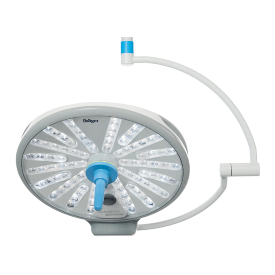
Page 19: Polaris 600 Light With Sterilizable Handle E
C Light control panel D Sterilizable handle E E Lens with LED F Bottom glass A Gimbal mounting Polaris 600 light with sterilizable handle E and MedView camera A Gimbal mounting B Integrated handle C Light control panel D Sterilizable handle E... -
Page 20: Light Control Panel
Reduce illuminance key: Increase illuminance key: Set color temperature key: Set light field diameter key: Switch ambient light (Endo light) on/off – For further information on controlling the lighting, see "Operation" on page 40. Instructions for use Polaris 600... -
Page 21: Medview Camera (Option)
MedView camera (option) The MedView camera is permanently installed in the light head. It is located in a segment next to the LED bulbs. Polaris 600 remote control for MedView camera key: MedView camera on/standby key: Zoom out video image (Wide) -
Page 22: Wall-Mounted Control Panel For 2 Polaris 600 Lights And A Medview Camera (Configuration Example)
Overview Wall-mounted control panel for 2 Polaris 600 lights and a MedView camera (configuration example) For a Polaris 600 light with MedView camera, the camera control area is on the right-hand side of the shared wall-mounted control panel. Light control area... -
Page 23: Or Panel (Option)
Overview OR panel (option) The OR panel is a messaging and operating panel. It is used for operating a Polaris 600 light system in operating rooms and for displaying operational and error messages. Polaris 600 control interface (option) The Polaris 600 control interface is an interface... -
Page 24: Display Mounts
B Single display mount B Double display mount C Display C Display D Sterilizable handle E D Sterilizable handle E Abbreviations Abbreviation Explanation Electromagnetic compatibility High Definition Infrared Light-emitting diode Sterilizable han- Sterilizable handle, ergonomic dle E Instructions for use Polaris 600... -
Page 25: Symbols
The product is a medical device Radio transmitter (CE conformity assessment pro- cedure) On/off (radio receiver) Quantity Direct voltage Storage temperature range Alternating voltage Relative humidity Ambient pressure Part number Lot number Serial number Revision index Instructions for use Polaris 600... -
Page 26: Operating Concept
Operating concept Operating concept Operating controls and their functions on the Polaris 600 light This table is applicable to light systems consisting of Polaris 600 lights, with or without a MedView camera. This table shows which control elements can be used to make which settings for the functions. -
Page 27: Operating Controls And Their Functions On The Polaris 600 And Polaris 100/200 Light System
Operating concept Operating controls and their functions on the Polaris 600 and Polaris 100/200 light system This table is applicable to light systems consisting of Polaris 600 lights, with or without a MedView camera, and Polaris 100/200 lights. This table shows which control elements can be used to make which settings for the functions. -
Page 28: Sterilizable Handle E
Operating concept Polaris 600 remote control for MedView camera Light field diameter – Illuminance – Color temperature – Synchronization – Ambient light (Endo light) – MedView camera Sterilizable handle E illuminance and the light field diameter. NOTE The sterilizable handle E will lose its functionality... -
Page 29: Wall-Mounted Control Panel (Option)
The wall-mounted control panel can incorporate up to 3 light control panels. Optionally it can include a camera control panel. The keys on the wall-mounted control panel are pressure-sensitive, i.e., a certain pressure must be applied by the finger. Instructions for use Polaris 600... -
Page 30: Color-Coding Of The Lights On The Wall-Mounted Control Panel
– The uppermost light control panel on the wall- mounted control panel and the corresponding color code are always assigned to the uppermost light on the arm system. Instructions for use Polaris 600... -
Page 31: Assembly And Preparation
When positioning the swivel arms and the Risk of infection attached devices, take care not to use force to pull the arm system beyond the stops. Personnel and patient may become infected by a non-sterile handle. Use only sterile handles. Instructions for use Polaris 600... -
Page 32: Preparing The Light System
"Replacing the battery in the Polaris 600 remote control for MedView Checking the Polaris 600 remote control for the camera" on page 65. MedView camera – Status LED does not light: the battery is ... - Page 33 Risk of patient injury The sterilizable handle can fall down into the operating field if it is not engaged properly. The handle must be checked for secure attachment after it has been fitted to the inner handle. Instructions for use Polaris 600...
- Page 34 OR personnel may hold the light steady. Risk of personal injury and property damage The handle can fall down into the operating field if it is not fitted properly. The handle may only be fitted by users. Instructions for use Polaris 600...
- Page 35 Specifications: – The dead weight of the single display mount is 5.5 kg (including handle and accessory box). – The dead weight of the double display mount is 11 kg (including handle and accessory box). Instructions for use Polaris 600...
- Page 36 WARNING Risk of personal injury and property damage The handle can fall down into the operating field if it is not fitted properly. The handle may only be fitted by users. Instructions for use Polaris 600...
- Page 37 The handle must be checked for secure attachment after it has been fitted to the inner handle. – To remove the handle, see the supplement to the instructions for use concerning reprocessing of Polaris. Instructions for use Polaris 600...
- Page 38 The disposable handle is intended solely for secure attachment after it has been fitted to single use. The disposable handle must not the inner handle. be reused. The disposable handle must be free from damage. Instructions for use Polaris 600...
- Page 39 The disposable handle must be checked for secure attachment after it has been fitted to the inner handle. – To remove the disposable handle, see the supplement to the instructions for use concerning reprocessing of Polaris. Instructions for use Polaris 600...
-
Page 40: Operation
Risk of personal injury and property damage Avoid collisions between the light head/display mount or parts of the arm system and other objects. The travel path must be clear before the product is adjusted in height or swiveled. Instructions for use Polaris 600... - Page 41 1 Take hold of the handle (A) in the grip area to position the light. position the light. The light head is held at its new position. The light head is held at its new position. Instructions for use Polaris 600...
- Page 42 1 Take hold of the integrated handle (A) to position the light. The light head is held at its new position. 1 Take hold of the integrated handle (A) to position the light. The light head is held at its new position. Instructions for use Polaris 600...
-
Page 43: Positioning A Light System
Position the light so that the light field is not directed towards the unprotected eyes of the patient. Instructions for use Polaris 600... - Page 44 A light head must not illuminate any other light head. NOTE A distance of 100 cm (39.37 in) from the bottom glass of the light to the operating field is recommended to achieve the optimum illumination of the operating field. Instructions for use Polaris 600...
-
Page 45: Positioning The Medview Camera
(B) at all times. The optimum distance between the MedView camera (from the bottom glass of the light) and the operating field is 90 cm to 130 cm (35.43 in to 51.18 in). Instructions for use Polaris 600... -
Page 46: Positioning A Display
The display is held in its new position. When positioning the swivel arms and the attached devices, take care not to use force to pull the arm system beyond the stops. Instructions for use Polaris 600... -
Page 47: Status Leds
The light is in standby mode. The light is not being supplied with power. – The status LED (A) is lit orange. There is a light system fault, see "Fault – Cause – Remedy" on page 67. Instructions for use Polaris 600... -
Page 48: Switching The Light On And Off
Polaris 600 light When the Synchronization function is activated sends a request to all the other Polaris 600 lights on the wall-mounted control panel, the control in the light system. The request contains the value... - Page 49 Operation Polaris 600 lights in accordance with the request. Switching off the Synchronization function All the Polaris 600 lights now have the same color temperature and illuminance. When the Synchronization function is activated, the Polaris 600 lights can be switched into Standby mode individually.
-
Page 50: Setting The Illuminance
Restriction when a Polaris 600 light is combined with Polaris 100/200 lights The Polaris 100/200 light does not accept any requests from a Polaris 600 light or the wall- mounted control panel. The illuminance is always set individually on the Polaris 100/200 light. - Page 51 Only one finger at a time must touch the operating section. 2 When the key (A) is pressed twice, the next LED (C) of the LED indicator lights up with half brightness. Instructions for use Polaris 600...
- Page 52 The change in the illuminance is shown by the LED indicator (B). – For further information on illuminance, see "Technical light data" on page 92. The change in the illuminance is shown by the LED indicator (B). Instructions for use Polaris 600...
- Page 53 [W/m Polaris 600 (A) Acceptable 600 W/m Polaris 600 (A) Acceptable 1200 W/m Polaris 600 (B) Polaris 200 (A) Acceptable 1200 W/m Polaris 200 (B) Polaris 600 (A) Acceptable 1200 W/m Polaris 200 (B) Instructions for use Polaris 600...
- Page 54 Polaris 600 (A) Polaris 200 (B) Acceptable 1800 W/m Polaris 200 (C) Polaris 600 (A) Polaris 600 (B) Acceptable 1650 W/m Polaris 100 (C) Polaris 600 (A) Polaris 100 (B) Acceptable 1500 W/m Polaris 100 (C) Instructions for use Polaris 600...
-
Page 55: Color Temperature Function
4 If the highest color temperature has been reached, pressing the key (A) again will reset the color temperature to its lowest value. – For further information on color temperature, see "Technical light data" on page 92. Instructions for use Polaris 600... -
Page 56: Light Field Diameter Function
– The light field diameter when the light is switched on is the same as the light field diameter set before the light was switched off. 1 Press the key (A). The light field diameter is increased by one step. Instructions for use Polaris 600... - Page 57 – For further information on the light field diameter, see "Technical light data" on page 1 Double-tap with one finger (A). The light field diameter is increased by one step. Instructions for use Polaris 600...
-
Page 58: Ambient Light Mode (Endo Light)
Polaris 600 lights can be switched into Ambient light mode individually. This will deactivate the Synchronization function. When a Polaris 600 light in the light system is in Ambient light mode, the key on this light is deactivated. When the key is pressed, the Synchronization function is not activated. -
Page 59: Operating The Medview Camera Using The Wall-Mounted Control Panel
Operation Operating the MedView camera using the wall-mounted control panel For a Polaris 600 light with MedView camera, the Switching the MedView camera off camera control area is on the right-hand side of the shared wall-mounted control panel. Switching the MedView camera on ... - Page 60 3 The change in the image detail is shown by the LED indicator (C). The status LED (B) is not lit. The larger the image detail becomes, the more LEDs light up. The smaller the image detail becomes, the fewer LEDs light up. Instructions for use Polaris 600...
- Page 61 4 The change in the exposure is shown by the LED indicator (C). The lighter the video image becomes, the more LEDs light up. The darker the video image becomes, the fewer LEDs light up. Instructions for use Polaris 600...
- Page 62 3 Press the key (B). NOTE The camera focuses on a closer object. The Manual focus function must be activated if the current focus setting is to be maintained without continuous automatic focusing taking place. Instructions for use Polaris 600...
- Page 63 The white balance for the camera takes place automatically, i.e., the camera adjusts itself automatically to the color temperature of the Polaris 600 light. NOTE The MedView camera adjusts itself automatically to the color temperature selected for the Polaris 600 light. Instructions for use Polaris 600...
-
Page 64: Operating The Medview Camera Using The Polaris 600 Remote Control For Medview Camera
Operation Operating the MedView camera using the Polaris 600 remote control for MedView camera Operating the remote control Positioning the remote control The remote control keys are identical to the camera control keys on the right side of the wall- mounted control. -
Page 65: Replacing The Battery In The Polaris 600 Remote Control For Medview Camera
Operation Replacing the battery in the Polaris 600 remote control for MedView camera Battery types 6LR61, 6F22 or 1604D of size 9 V block can be used in the remote control. These battery types must not be charged. Fluid may leak from the battery if the remote control is not used for a long time. - Page 66 7 Close the lid. 8 Close the housing flap. 9 Perform a function test, see "Checking for operational readiness before each use" on page 31. 10 Properly dispose of the old battery. 11 Charge rechargeable batteries as required. Instructions for use Polaris 600...
-
Page 67: Troubleshooting
The LEDs on the mains connection component are numbered and indicate the status of the light system. Supply mains Emergency power Output voltage Initialize in progress Contact service Initialize system System number A System number B Instructions for use Polaris 600... - Page 68 Continuously yel- Electronics fault Inform Dräger- Communication with the light system Service disrupted Flashing yellow Light system is not initialized Perform initial- Contact service ization in accor- dance with assembly instructions or contact Dräger- Service Instructions for use Polaris 600...
- Page 69 Internal fault in the mains connection power) component Notify Dräger- Input source is unknown Service Output volt- Flashing yellow Output voltage level is unknown age to light (Output volt- age) Notify Dräger- Continuously yellow Service (Con- tact service) Instructions for use Polaris 600...
- Page 70 Dräger- Service Continuously green Mains power is available No remedial action nec- Status LED (C) essary Continuously orange Mains power is interrupted (light Notify the in-house system is being supplied with technician emergency power) Instructions for use Polaris 600...
- Page 71 (Endo light) essary panel Continuously orange on the wall-mounted control panel Polaris 600 remote control for MedView camera Fault Cause Remedy Remote control is not within the reception range of the IR Aim the remote control at...
- Page 72 4 Set the on/off switch on the radio receiver to I. The connection will be reestablished. This procedure takes up to 30 seconds Video image is Unknown Notify DrägerService not displayed and cannot be rees- tablished Instructions for use Polaris 600...
-
Page 73: Reprocessing
Reprocessing Reprocessing Further information – For correct reprocessing of the product, read and observe the supplement to the instructions for use concerning reprocessing of Polaris. Instructions for use Polaris 600... -
Page 74: Maintenance
The switch required to do this is a part of the mains connection component. The mains connection component must be prevented from being switched on again unintentionally. Instructions for use Polaris 600... - Page 75 Check the horizontal and vertical joints of the arm system for free movement and re-grease them if nec- essary. Check the height stop of the arm system and read- just it if necessary. Instructions for use Polaris 600...
- Page 76 Check the arm system (central axis, swivel arm, and spring arm) for colli- sion damage (welding seams free of cracks). Check for deformations of the arm system and whether parts have become loose. Instructions for use Polaris 600...
- Page 77 Check for paint damage and cracks in plastic parts. Check whether all plastic parts are present and in the correct position. Check that the rating plate is present and is readily legible. Perform functional and visual inspection. Instructions for use Polaris 600...
- Page 78 Check the horizontal and vertical joints of the arm system for free movement and re-grease them if nec- essary. Check the height stop of the arm system and read- just it if necessary. Instructions for use Polaris 600...
- Page 79 Check the arm system (central axis, swivel arm, and spring arm) for colli- sion damage (welding seams free of cracks). Check for deformations of the arm system and whether parts have become loose. Instructions for use Polaris 600...
- Page 80 Visually inspect the sup- ply lines for abrasion wear in the housing. Check that the rating plate is present and is readily legible. Perform functional and visual inspection. Instructions for use Polaris 600...
-
Page 81: Maintenance
Specialized service per- screws, see "Checking sonnel the circlip on the lower swivel arm to the spin- dle joint" on page . – Grease the brake screws on the swivel arm and the spring arm. Instructions for use Polaris 600... -
Page 82: Repair
Repairs may be performed only by specialized service personnel. It is recommended that only original parts from Dräger are used and that the parts are replaced by DrägerService. A service contract with DrägerService is recommended. Instructions for use Polaris 600... -
Page 83: Adjusting The Arm System
45° Remove covers and panels in accordance with the Polaris 600 assembly instructions. 1 Insert a 5 mm Allen key into the adjustment opening (1). Pull the spring arm down a little to relieve the adjusting screw in the arm. - Page 84 If the spring arm rises, the spring force is too guide the snap-in hook (1) out of the cover. high 3 Push the screwdriver with the panel (3) to the Turn the Allen key right (clockwise). rear. Instructions for use Polaris 600...
- Page 85 1 Adjust the braking force on the joint using the set screw (A). Use an Allen key (size 4 mm) for this. 2 Adjust the braking force of the joint using the set screw (A). Instructions for use Polaris 600...
-
Page 86: Checking The Locking Devices On The Arm System
24.5 mm (0.965 in). The material thickness (B) of the locking device must be at least 2.1 mm (0.083 in). Grease the 2 locking devices on each swivel arm with microGLEIT GP 360 paste. Instructions for use Polaris 600... - Page 87 – Remove/fit the locking devices in accordance the spring arm with the technical documentation. – Remove/fit the 2 brake screws in accordance with the technical documentation. Grease the 2 brake screws with microGLEIT GP 360 paste. Instructions for use Polaris 600...
-
Page 88: Acceptance And Handover
A written record of the handover is filed for reference. The users are instructed on the use of the system. Polaris 600 remote control for MedView camera It may be necessary to change the room address if MedView cameras are operated by remote control in adjacent operating rooms which are only separated by a pane of glass. -
Page 89: Disposal
Germany, the respective national regulations must be complied with. Disposal of accessories Dispose of the following articles in accordance with – Sterilizable handle the hospital's hygiene regulations: – Dräger disposable handle – Sterilizable handle E Instructions for use Polaris 600... -
Page 90: Technical Data
(for which CISPR 11 Class B is normally required), this equipment might not offer adequate protection to radio- frequency communication services. The user might need to take mitigation measures, such as relocating or reorienting the equipment. Instructions for use Polaris 600... - Page 91 To ensure that the full functional integrity of this device is not compromised, there must be a separation distance of at least 1.0 m (3.3 ft) between this device and wireless high-frequency communication equipment. Instructions for use Polaris 600...
-
Page 92: Ambient Conditions
Light field diameter at a distance of 1 m (39.37 in) 190 mm (7.48 in) 240 mm (9.45 in) 120 mm (7.72 in) 135 mm (5.31 in) Depth of illumination L1+L2 (20 %) 1300 mm (51.18 in) 1300 mm (51.18 in) Instructions for use Polaris 600... - Page 93 1) Light settings (1 m (39.37 in) distance to light-emitting surface): Central color temperature set to 4400 K and light field diameter set to "Small". 2) The maximum total irradiance is attained at a distance of 91 cm (35.83 in). Instructions for use Polaris 600...
-
Page 94: Electrical Data
Light at 50 % illuminance 70 VA Light in standby mode 35 VA Maximum connected load Light head Max. 240 VA Display spring arm Max. 800 VA Total nominal power of all LED bulbs 70 W Instructions for use Polaris 600... -
Page 95: Mechanical Data
3.8 mm (Wide) to 38 mm (Tele), 1.8 to 3.4 Auto shutter Minimum illuminance 100 lx Signal/Noise ratio 50 dB White balance Automatic adjustment to the color temperature of the Polaris 600 light Freeze frame Focus Autofocus (AF) Manual focus Instructions for use Polaris 600... -
Page 96: Polaris 600 Remote Control For Medview Camera
78 mm x 46 mm x 49 mm (3.07 in x 1.81 in x 1.93 in) Weight <250 g (0.55 lb) All details are subject to manufacturing tolerances. Polaris 600 remote control for MedView camera Signal transmission Infrared radiation Range Max. 7 m (275.6 in) - Page 97 115 mm x 93 mm x 23 mm (4.53 in x 3.66 in x 0.91 in) (without power plug) 130 mm x 93 mm x 23 mm (5.12 in x 3.66 in x 0.91 in) (with power plug) Instructions for use Polaris 600...
-
Page 98: Combination With System Components
Integrated handle (at the light head) Non-sterile Light control panel (on the gimbal mounting) Non-sterile Wall-mounted control panel Non-sterile Polaris 600 remote control for MedView camera Non-sterile Classifications Protection class according to IEC 60601-1 Mains connection component Protection class 1... -
Page 99: Display Mounts
Technical data Classifications (continued) UMDNS code for the Polaris 600 light system 12-282 Universal Medical Device Nomenclature System (nomenclature for medical devices) Display mounts Electrical data Primary power supply at the power supply unit for 100 V~ to 240 V~... -
Page 100: Classification
1) The maximum load refers exclusively to the display mount components. The maximum load depends on the version and configuration of the arm system. 2) Storage only indoors or in covered spaces. Classification Protection class according to IEC 60601-1 Protection class 1 Arm system IP 30 Display mounts IP 10 Instructions for use Polaris 600... -
Page 101: List Of Accessories
Handle adapter for disposable sleeves for lights (optional), manufacturer Covidien For MedView camera Polaris 600 remote control for MedView camera G24065 1) Not covered by IEC 60601-2-41 standard. 2) If the handle adapter for disposable sleeves is used, the corresponding disposable sleeves must be ordered directly from Covidien. -
Page 102: List Of Accessories For Display Mounts
(optional), manufacturer Covidien 1) Not covered by IEC 60601-2-41 standard. 2) If the handle adapter for disposable sleeves is used, the corresponding disposable sleeves must be ordered directly from Covidien. Instructions for use Polaris 600... -
Page 103: Index
Fault – Cause – Remedy ....67 Polaris 600 remote control ....21 Freeze frame . - Page 104 Zoom ....... . . 60 Instructions for use Polaris 600...
- Page 105 This page has been left blank intentionally. Instructions for use Polaris 600...
- Page 106 Draeger Medical UK Ltd. Hertfordshire, HP2 7BW, UK Email: Medical.Devices@draeger.com Manufacturer Drägerwerk AG & Co. KGaA Moislinger Allee 53 – 55 D-23542 Lübeck Germany +49 451 8 82-0 +49 451 8 82-2080 http://www.draeger.com 9511551 – 6932.155 en Á95115516È © Drägerwerk AG & Co. KGaA Edition: 2 –...
Need help?
Do you have a question about the Polaris 600 and is the answer not in the manual?
Questions and answers