
Related Manuals for gefran ILI Series


Summary of Contents for gefran ILI Series
- Page 1 PRESSURE SENSORS FOR HIGH TEMPERATURE IO-Link IMPACT Cod. 80618 edit. 12/2019 - ENG...
- Page 2 INDEX 1. GENERAL INFORMATION ................................4 1.1. General information .................................4 1.2. Copyright ....................................4 1.3. Correct use ....................................4 2. MELT IO-LINK ....................................4 2.1. Impact IO-Link models ................................4 2.2. Transducer General Information .............................4 2.3. Models .....................................5 3. TECHNICAL DATA ...................................6 4. MECHANICAL DIMENSIONS ................................7 5.
-
Page 3: Table Of Contents
10. RELAY APPLICATION NOTES ..............................33 11. RESOLUTION PROBLEMS .................................37 12. APPENDIX B: IP PROTECTION..............................38 13. APPENDIX C: ACCURACY CLASS .............................39 13.1. Calibration Curve .................................39 13.2. Repeatability ..................................39 13.3. Hysteresis ....................................40 13.4. Linearity ....................................40 14. APPENDIX D: REGISTRATION MAINTENANCE ........................41 80618_MAN_IO-LINK IMPACT_12-2019_ENG... - Page 4 ILI and must be kept near the equipment for easy reading and consultation. It must be read, understood, and strictly follow in order to avoid and prevent accidents and/or malfunctions. Gefran will not be liable for any injury to people and/or damage to property deriving from disregard of this manual. 1.2. Copyright Any reproduction of this document, even partial or for internal use, requires Gefran’s approval.
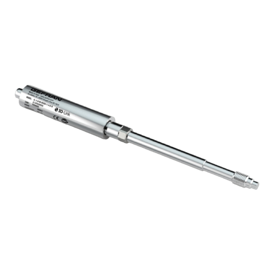
- Page 5 2.3. Models DIGITAL OUTPUT ILI0 ILI1 80618_MAN_IO-LINK IMPACT_12-2019_ENG...
- Page 6 (1) BFSL method (Best Fit Straight Line): includes combined effects of Non-Linearity, Hysteresis and Repeatability (according to IEC 62828-2). Sensors are manufactured in compliance with: - EMC compatibility directive - RoHS directive - Machinery directive Electrical installation requirements and Conformity certificate are available on our web site: www.gefran.com 80618_MAN_IO-LINK IMPACT_12-2019_ENG...
- Page 7 4. MECHANICAL DIMENSIONS For the mechanical dimensions keep as reference the product datasheets or Gefran website www.gefran.com 5. INSTALLATION AND POSITIONING ON THE MACHINE TECHNICAL DATA Extrusion processes require very high temperatures. Extrusion pressure can be checked by means of especially designed transducers.
- Page 8 Drilling kit A drilling kit with formed tools for drilling, reaming and tapping is available to facilitate correct preparation of the assembly seat. The assembly seat must be perfect to assure proper transducer function and long lifetime. Drilling kits are available in the following versions: KF12, KF18.
- Page 9 TRANSDUCER INSTALLATION Installation procedure 1) Make sure the drilling procedure has been realized correctly. If the sensor is installed in a previously used hole, make sure the hole is completely clean and free of any plastic residual. 2) Remove the protective cap from the sensor top. 3) Lubrificate the thread with non-grip grease such as Neverseez (Bostik), or C5A (Felpro), or equivalent.
- Page 10 ORDER CODES FOR TOOLS and ACCESSORIES SF 18 MOUNTING BRACKET DUMMY PLUG 1/2-20UNF CLEANING TOOL KIT M18x1,5 1/2-20UNF M18x1,5 DRILL KIT 1/2-20UNF M18x1,5 5.3. TORQUING THE SENSOR Screw the sensor after checking the correct shape of the side. Hold the flexible part while screwing the jam bushing. For safety operations at least 6 pitch of the jam bushing must be screwed into the hole.
- Page 11 6. INSTALLATION AND ELECTRICAL CONNECTIONS 6.1. General precautions The system must be used only in accordante with the required protection level. The sensor must be protected against accidental knocks and used in accordante with the instrument’s ambient characteristics and performance levels. The sensors must be powered with non-distributed networks and always at lengths of less than 30 mt.
- Page 12 Notes: • For IO-Link only version connect the transducer to a standard IO-Link master through a standard unshielded M12 cable (max length 20m according to IO-Link specification) IO-link master Unshielded IL transducer cable Machine Press Equipment Rod / Pressure intake Ground •...
- Page 13 Note In accordance with IEC/EN 62061, IEC/EN 61508 and ISO/EN 13849, ILI series transducers also comply with EN 61326-3-1 “Electrical equipment for measurement, control, and laboratory use - immunity requirements for safety-related systems and for equipment intended to perform safety-related functions (functional safety) - General industrial applications”.
- Page 14 7. COMMAND MODES 7.1. IO-Link Information Table 2 IO-Link information Port Class Baud rate COM2 (38.4 kB) IO-Link version (1) Profile Generic Smart Sensor Standard = 2 Bytes (Pressure + SSCs) Process data input length T version = 4 Bytes (Temperature + Pressure + SSCs) Process output data length Standard = 2,7 ms Min Cycle Time...
- Page 15 7.4. Parameterization data This paragraph includes list and explanation of relevant available parameters for IL transducer, listed according to IO-Link specification • Predefined parameters - System Access Index Subindex Object name Length Data Type Value (example) Description See Table 3 0x0002 0x00 System Command...
- Page 16 • Predefined parameters – Identification Access Index Object name Length Data Type Value (example) Description Index 0x0010 0x00 VendorName String GEFRAN spa 0x0011 0x00 VendorText String www.gefran.com ILI1-S-5-M-B07C-1-4-D-P 0x0012 0x00 ProductName Max 64 String Full description of product T000A000X00 0x0013...
- Page 17 Table 6 Error and Warnings in Detailed Device Status Output behavior Event Code Event Type Device Status Possible failure Reset Mode Note IO-Link Relay Analog Pressure value Functional Safety Related Power supply cable Valid for SIL 2 / Open Remove failure broken PL d Diagnostic Valid for SIL 2 /...
- Page 18 Event Code Event Type Device Status Description Note 0x18A2 Notification event for Relay Threshold Changed, value confirmed 0x18A3 Notification event for Relay Threshold Changed, abort *In case of Block Parameterization (not Write Direct) this event happens each time one of any parameter is written; this behavior is required for IO-Link certification test;...
- Page 19 Access Data VALUE (exam- Index Object Name Length Value Range Gradient Offset Unit Description Index Type ple) 0x0000: no hysteresis According to MU 0x03 Hyst UInt16 Other values: 0…10%FS See Table 10 hysteresis in pressure unit Defines the Switch- 0x003E SSC2Param Record points for Channel...
- Page 20 • Device parameters – Extended Index Access Length Data Value Value Index Object Name Gradient Offset Unit Description Index (Bytes) Type (example) Range Calibration date (yyyym- 0x0100 0x00 Calibration Date RO RO RO 8 String 20190825 mdd) 0: false Cal Mode Enable (default) Enable/Disable the Cali- 0x0101...
- Page 21 Access Length Data Value Value Index Object Name Gradient Offset Unit Description Index (Bytes) Type (example) Range Rangeability functionality, specifies the end value of According range for Analog output Upper Range Value (URV)** to MU 0x0118 0x00 RO R/W R/W 2 UInt16 33%FS…FS (limited from 33 to 100%...
- Page 22 7.6. Switching signal channels (SSCs) configuration The IL transducer offers two digital ouput (SSCs): • Logical, inside process data (bit0 and bit1), during IO-Link mode communication • Physical, on pin 4 and pin 2 (*) of M12 connector, during SIO mode. SSCs commute according to the overtaking (high or low) of threshold value(s) based on the main process data, that is pressure.
- Page 23 Figure 2 Two Points Mode Figure 3 Window Mode SP1 and SP2 points can be set in two ways: • through direct setting of the value of objects: - SSC1Param.SP1 (Index 0x003C, sub-index 1) - SSC1Param.SP2 (Index 0x003C, sub-index 2) - SSC2Param.SP1 (Index 0x003E, sub-index 1) - SSC2Param.SP2 (Index 0x003E, sub-index 2) •...
- Page 24 7.7. Reranging (LRV/URV) – only for SIL 2 / PL d analog output version – The IL transducer has an optional analog output on pin 5 with reference on pin 3 of M12 connector (only for SIL 2 / PL d analog output version).
- Page 25 7.8. Relay Threshold change – only for SIL 2 / PL d relay output version – The IL transducer has an optional relay output contact on pin 2 and 5 of M12 connector (only for SIL 2 / PL d relay output version). This contact can be used as Safety function for safety related application up to SIL 2 / PL d.
- Page 26 7.11. Enable CAL parameter The Enable CAL parameter (see par 7.4 – Extended index – index 0x0101) allows the user to bring the output value, both analog (where available) and IO-Link, to the 80% of Full Scale; this option is used during calibration procedure as described at par. 5.2. Action on this parameter must be done by skilled and trained personnel, can be acted only by Specialist and Maintenance users and should be executed only during installation procedure or maintenance, according to following procedure: •...
- Page 27 Even if these are designed with a thick diaphragm, they must be always transported and stocked with the protection cap and with the package. Gefran allows melt pressure sensors of own production, also defective units or damage by the use, for the disposal. 80618_MAN_IO-LINK IMPACT_12-2019_ENG...
- Page 28 9. FUNCTIONAL SAFETY NOTES (FOR SIL 2 / PL D CERTIFIED VERSIONS ONLY) -WAITING FOR NOTIFIED BODY CERTIFICATION- 9.1. Application The pressure sensors ILI SIL 2 / PL d perform the following safety function: The safety function performed by the sensor is the correct measurement and transduction of pressure value, read according to accuracy specification defined in the datasheet and in this user manual, to be compared with a determined safety threshold (high threshold), or de-energizing of a relay contact normally energized, at the overcoming of a set safety threshold.
- Page 29 1) the IL transducer has analog output and is power supplied through an IO-Link master; IO-Link communication can be on or not; the transducer detects the pressure and gives in output an analog electrical value proportional to the pressure itself; SRP/CS compares the signal with its internal alarm threshold: if the threshold is exceeded the SRP/CS will stop the pressure generation systems.
- Page 30 4) the IL transducer has relay output and is power supplied externally; the sensor detects the pressure and compares it with a determined threshold; if the threshold is exceeded, the relay will open; the relay output is interfaced with an enable input of the pressure generating system motor drive;...
- Page 31 • Sensor calibration test (Proof Test) The purpose of the test is to verify the correctness of the transduction curve of the sensor. It is carried out by applying known pressure points to the transducer and checking the values reported by the probe. Periodicity: every two years •...
- Page 32 9.8. Indications and alarms The sensors of the ILI SIL 2 / PL d series can have two different electrical output: analog amplified (0,5..10,5 V o 4..20 mA) or a relay output. IO-Link communication cannot be considered a safety channel, even if: •...
-
Page 33: Relay Application Notes
10. RELAY APPLICATION NOTES Contacts Relay manufacturers assume you will be using resistive loads when they rate their relays. The load is a simple resistive element, and it is assumed that the current flow through the contacts will be fairly constant, although some increase may occur due to arcing during “make”... - Page 34 (1) Incandescent Lamp Load (3) Fluorescent Lamp Load (2) Mercury Lamp Load i/i ≈ 3 ≈ 5 to 10 B remsen Contacts (for high power factor type) Incandescent lamp 10 seconds 3 to 5 or less minutes Approx. 1/3 second The discharge tube, transformer, choke coil, capacitor, etc, are combined in common discharge lamp circuits.
- Page 35 Figure 11 Generally, a concave formation appears on the cathode and a convex formation appears on the anode. Contact protection circuit Use of contact protective devices or protection circuits can suppress the counter emf to a low level. However, note that incorrect use will result in an adverse effect. Typical contact protection circuits are given in the table below.
- Page 36 In the actual circuit, it is necessary to locate the protective device (diode, resistor, capacitor, varistor, etc.) in the immediate vicinity of the load or contact. If located too far away, the effectiveness of the protective device may diminish. As a guide, the distance should be within 50cm. Switching Capacitive Loads Using relays to switch capacitive loads requires special care.
-
Page 37: Resolution Problems
11. RESOLUTION PROBLEMS All Gefran sensors are built in conformity to UNI EN ISO 9001: 2000 In case of malfunction, you can run a series of simple checks to identify the type of fault. If the problem is caused by a sensor malfunction, the sensor MUST be returned to Gefran. -
Page 38: Appendix B: Ip Protection
Example: the protection index IP45 indicates a protection level of 4 against solids and a protection level of 5 against liquids. Attention: these indexes are valid under standard ambient conditions. Gefran Melt transducers and transmitters are built with protection index IP65. Protection against solid objects... -
Page 39: Appendix C: Accuracy Class
13.2. Repeatability Repeatability is defined as the ability to reproduce reads in the same direction and under the same conditions when the same pressure is applied consecutively. The maximum repeatability error of every Gefran sensor is 0.1% FS Rise curve Pressure... -
Page 40: Hysteresis
13.3. Hysteresis The maximum read difference for each reading in a specific range when the value is reached, first in rise and then in descent. The maximum hysteresis for every Gefran sensor is 0.1% F Rise curve Pressure read Descent... -
Page 41: Appendix D: Registration Maintenance
Dependent linearity error (End point) Dependent linearity error is the deviation between the real characteristic of the transducer and the straight line passing through the two ends; expressed in % of FS. Independent linearity error (BFSL) Independent linearity error (BFSL) is the deviation between the real characteristic of the transducer and the straight line of minimum squares. - Page 42 Note 80618_MAN_IO-LINK IMPACT_12-2019_ENG...
- Page 43 80618_MAN_IO-LINK IMPACT_12-2019_ENG...
- Page 44 Gefran SPA Via Sebina, 74 25050 Provaglio d’Iseo (BS) Tel. +39 030 9888 1 Fax +39 030 9839063 www.gefran.com...
Need help?
Do you have a question about the ILI Series and is the answer not in the manual?
Questions and answers