Table of Contents
Advertisement
Quick Links
80175G_MAN_I3-IE-IN-IX_I7_11-2018_ENG
I3 - IE - IN - IX - I7
INSTRUCTION MANUAL
cod. 80175G Edit. 11/2018 - ENG
ATTENTION!
This manual is an integral part of the product,
and must always be available to operators.
This manual must always accompany the
product, including if it is transferred to another user.
Installation and/or maintenance workers MUST
read this manual and scrupulously follow all of the
instructions in it and in its attachments.
GEFRAN will not be liable for damage to
persons and/or property, or to the product itself, if the
following terms and conditions are disregarded.
The customer must respect trade secrets.
Therefore, this manual and its attachments may
not be tampered with, changed, reproduced, or trans-
ferred to third parties without GEFRAN's authorization.
1
Advertisement
Table of Contents

Related Manuals for gefran IE Series


Summarization of Contents
1. General Information
General Information Details
Manual must be kept near equipment for easy reading and consultation. Must be read and understood.
Copyright
Any reproduction of this document, even partial or for internal use, requires Gefran's approval.
Correct Use
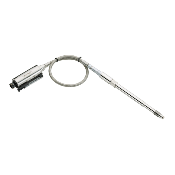
Melt pressure sensors are designed to measure pressure and temperature of melted plastic. Correct temp range is 350°C.
3. Installation and Positioning on the Machine
3a - Installation Seat
The installation seat must be realized with specific dimensions and coaxiality to ensure proper transducer function and lifetime.
3. Installation and Positioning on the Machine (Continuation)
Drilling Procedure
Steps for drilling, reaming, and tapping the installation seat using specific tools to ensure correct preparation.
Installation Seat Check
Check the assembly seat dimensions after preparation and before transducer installation using a dummy plug.
Transducer Installation
Installation Procedure
Steps for installing the transducer, ensuring drilling procedure is correct, cleaning, lubricating, and torqueing.
Removal
Dummy plugs with identical mechanical dimensions are available for removing the transducer from its seat.
Brackets
Models with flexible sheaths require housing precise fixing. Suitable fastening brackets are recommended.
Extruder Starting
Bring the system to working temperature with the transducer installed and without pressure. Wait for uniform temperature.
Seat Cleaning & Cleaning Tool
The seat must be cleaned before transducer installation using a hard metal cutting tool.
3d - Wiring and Calibration
Connections
Sensors have to be connected as shown in diagram. Connect cable shield to female connector case for better immunity.
Calibration Procedure
Bring system to working temp, ensure stability, reset offset with autozero, calibrate to transducer data plate value.
4. Electronic Features and Procedures
4a - Autozero Function
Autozero function is activated by magnet or short-circuiting pins. Effect visible after 2 seconds.
4a - Autozero Function (Continuation)
2) CALIBRATION (CAL)
Calibration function activated by short-circuiting pin E-F for 1 sec. Signal unbalances to 80% FS during calibration.
3) TOTAL RESET OF THE CALIBRATION VALUES
Autozero function can be activated by magnet or short-circuiting pins. Zero and Span recalibrated to factory settings.
6. Sensor Technical Specification
6a - IN Series - Technical Data
Details accuracy, resolution, measurement range, overpressure, principle, power supply, output signal, temperature ranges, etc. for IN series.
7. Safety Manual for Performance Level “C” Sensors
Limitations and Maintenance
Device must be used by skilled people, following safety instructions for mechanical installation, electrical connection, and environmental conditions.
Electrical Connections
Voltage Output
Wiring diagrams for relay output (6-8 pin connector) for magnetic and external autozero versions.
Current Output
Wiring diagrams for relay output (6-8 pin connector) for magnetic and external autozero versions.
Command Modes
1) Autozero
Autozero function is activated by magnet or short-circuiting pins. Effect visible after 2 seconds.
Maintenance and Troubleshooting
Visual Inspection of Membrane and Thread
Evaluates abrasion/wearing due to mounting or process materials. Periodicity: every 2 years.
Installation Hole Check
Evaluates hole profile and dimensions to avoid failures or sensor bad functioning. Periodicity: every 2 years.
8. Relay Application Notes
Contacts
Relay manufacturers assume resistive loads. Contact life influenced by material, voltage, current, load type, switching frequency, etc.
Inductive Loads
Switching inductive loads is difficult due to arcing. Derate relay contacts to 40% of resistive load rating.
Capacitive Loads
High in-rush current when charging capacitors. Derate relay contacts to 75% of resistive load rating.
Motor Loads
Motors require large in-rush current at startup. Derate relay contacts to 20% of resistive rating.
Type of Load and Inrush Current
Table shows relationship between typical loads and their inrush currents.
Need help?
Do you have a question about the IE Series and is the answer not in the manual?
Questions and answers