Advertisement

Quick Links

80175G_MAN_I3-IE-IN-IX_I7_11-2018_ENG
I3 - IE - IN - IX - I7
INSTRUCTION MANUAL
cod. 80175G Edit. 11/2018 - ENG
ATTENTION!
This manual is an integral part of the product,
and must always be available to operators.
This manual must always accompany the
product, including if it is transferred to another user.
Installation and/or maintenance workers MUST
read this manual and scrupulously follow all of the
instructions in it and in its attachments.
GEFRAN will not be liable for damage to
persons and/or property, or to the product itself, if the
following terms and conditions are disregarded.
The customer must respect trade secrets.
Therefore, this manual and its attachments may
not be tampered with, changed, reproduced, or trans-
ferred to third parties without GEFRAN's authorization.
1

Advertisement

Table of Contents
loading

Summary of Contents for gefran I3 Series

  • Page 1 GEFRAN will not be liable for damage to persons and/or property, or to the product itself, if the following terms and conditions are disregarded.
  • Page 2: Table Of Contents

    5. Autocompensation effect on IMPACT series pag 15 6. Sensor technical specifications pag 16 6a. IN series pag 16 6b. I3 series pag 17 6c. IX series pag 18 6d. IE series - IE Performance Level “c” series pag 19 6e.
  • Page 3: General Informations

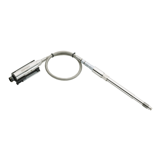
    GENERAL INFORMATION This manual applies to IN-I3-IX-IE series and to IE - I7 performance level “c” series produced by Gefran spa, via sebina 74-25050 Provaglio di’Iseo - BS- Italy. General information This manual must be kept near the equipment for easy reading and consultation.
  • Page 4: Installation And Positioning On The Machine

    INSTALLATION AND POSITIONING ON THE MACHINE TECHNICAL DATA Extrusion processes require very high temperatures. Extrusion pressure can be checked by means of espe- cially designed transducers. The IMPACT series sensors are suitable for pressure measurements with high temperature and are based on the piezoresistive technology.
  • Page 5 Drilling kit A drilling kit with formed tools for drilling, reaming and tapping is available to facilitate correct preparation of the assembly seat. The assembly seat must be perfect to assure proper transducer function and long lifetime. Drilling kits are available in the following versions: KF12, KF18. Drilling procedure 1) To drill hole (D4) up to a distance from the hole equal to the sum of (A+B+C) (tool 3).
  • Page 6 TRANSDUCER INSTALLATION Installation procedure 1) Make sure the drilling procedure has been realized correctly. If the sensor is installed in a previously used hole, make sure the hole is completely clean and free of any plastic residual. 2) Remove the protective cap from the sensor top. 3) Lubrificate the thread with non-grip grease such as Neverseez (Bostik), or C5A (Felpro), or equivalent.
  • Page 7: 3B. Torquing The Sensor

    ORDER CODES FOR TOOLS and ACCESSORIES SF 18 MOUNTING BRACKET DUMMY PLUG 1/2-20UNF CLEANING TOOL KIT M18x1,5 1/2-20UNF M18x1,5 DRILL KIT 1/2-20UNF M18x1,5 3b - Torquing the sensor Screw the sensor after checking the correct shape of the side. Hold the flexible part while screwing the jam bushing. For safety operations at least 6 pitch of the jam bushing must be screwed into the hole.
  • Page 8: 3C. Connecting Amplifier

    3c - Connecting amplifier (only for modular versions) The electronics must be connected to the primary part by aligning the 2 red points on each connector. Take care not to force the connectors together: check the correct aligning of the 2 red points. Fix the flexible sheath to the machine.
  • Page 9: 3D. Wiring And Calibration

    3d - Wiring and calibration Connections The sensors have to be connected as shown in the diagram on the next page. To obtain a higher immunity from field noise, connect the cable shield to the female connector case on sen- sor side.
  • Page 10: 3E. Electrical Output Connections

    3e - Electrical output connections I3 series IE series 80175G_MAN_I3-IE-IN-IX_I7_11-2018_ENG...
  • Page 11 IN series IX series Note: Power feeding through a galvanic isolation barrier. The cable shield is tied to connector via cable clamp 80175G_MAN_I3-IE-IN-IX_I7_11-2018_ENG...
  • Page 12 I7 series 8 pin connector 6 pin connector 8 pin connector (Binder) 4 pole cable PC02E-12-8P VPT07RA10-6PT2 M16 DIN/EN45326 Bendix (PT02A-10-6P) (09-0173-00-08) Blue Shield Orange Yellow or black Shielded cable 4x0.25 - 2m. Protection IP65 IE - LOAD DIAGRAM IX - LOAD DIAGRAM 10 11 12 13 14 15 16 17 18 19 20 21 22 23 24 25 26 27 28 29 30 31 32 Vcc (Volt) The diagram shows the optimum ratio between load and power supply for transmitters with 4…20mA output.
  • Page 13: 3F. Maintenance

    Even if these are designed with a thick diaphragm, they must be always transported and stocked with the protection cap and with the package. Gefran allows melt pressure sensors of own production, also defective units or damage by the use, for the disposal.
  • Page 14: Electronic Features And Procedures

    4. ELECTRONIC FEATURES AND PROCEDURES 4a - Autozero function The transmitter remains on the standard operating mode, till an external event happens. The possible channels to activate the additional functions are the following: - Pin CAL - Magnetic pen The operating manual explains the following features: 1) Autozero 2) Calibration (CAL) 3) Total Reset...
  • Page 15: Autocompensation Effect On Impact Series

    2) C (CAl) AlibrAtion Application mode Limits Result Start CAL: The whole Zero unbalancement in During the Calibration phase the The Calibration function is comparison to the zero done by the signal will be unbalanced to the activated by short-circuiting the manufacturer, has to be ±...
  • Page 16: Sensor Technical Specifications

    (1) BFSL method (Best Fit Straight Line): includes combined effects of Non-Linearity, Hysteresis and Repeatability. Sensors are manufactured in compliance with: - EMC compatibility directive - RoHS directive Electrical installation requirements and Conformity certificate are available on our web site: www.gefran.com 80175G_MAN_I3-IE-IN-IX_I7_11-2018_ENG...
  • Page 17: 6B. I3 Series

    (1) BFSL method (Best Fit Straight Line): includes combined effects of Non-Linearity, Hysteresis and Repeatability. Sensors are manufactured in compliance with: - EMC compatibility directive - RoHS directive Electrical installation requirements and Conformity certificate are available on our web site: www.gefran.com 80175G_MAN_I3-IE-IN-IX_I7_11-2018_ENG...
  • Page 18: 6C. Ix Series

    Sensors are manufactured in compliance with: - EMC compatibility directive - RoHS directive - ATEX Sensors are also tested according to NAMUR NE21 and NE43 recommendations Electrical installation requirements and Conformity certificate are available on our web site: www.gefran.com 80175G_MAN_I3-IE-IN-IX_I7_11-2018_ENG...
  • Page 19: 6D. Ie Series - Ie Performance Level "C" Series

    (1) BFSL method (Best Fit Straight Line): includes combined effects of Non-Linearity, Hysteresis and Repeatability. Sensors are manufactured in compliance with: - EMC compatibility directive - RoHS directive - machine directive Electrical installation requirements and Conformity certificate are available on our web site: www.gefran.com 80175G_MAN_I3-IE-IN-IX_I7_11-2018_ENG...
  • Page 20: 6E. I7 Performance Level "C" Series

    (1) BFSL method (Best Fit Straight Line): includes combined effects of Non-Linearity, Hysteresis and Repeatability. Sensors are manufactured in compliance with: - EMC compatibility directive - RoHS directive - machine directive Electrical installation requirements and Conformity certificate are available on our web site: www.gefran.com 80175G_MAN_I3-IE-IN-IX_I7_11-2018_ENG...
  • Page 21: Safety Manual For Performance Level "C" Sensors

    7. SAFETY MANUAL FOR PERFORMANCE LEVEL “C” SENSORS (FOLLOWING EN 13849-1) Designated category and fail exclusions The designated category to which are limited the use of safety related parts is Category 1. Legend: Input device (transducer) Logic solver Output device (actuator) Connections The safety function of the transducer is the correct transduction of the pressure in the extrusion chamber in order to detect overpressures and the overcoming of a fixed safety pressure threshold.
  • Page 22 SRP/CS interface and protection devices The SRP/CS interface is the multi-polar connector type 6 poles VEAM VP07RA10-6PT2 or the multi-polar connector type BINDER 8 poles M18 DIN/EN 45326, as illustrated in Figure 4, where are also pointed out the connections in case of voltage amplified output (4 wires: 2 for supply and 2 for signal) or current amplified (2 wires connection).
  • Page 23 ELECTRICAL CONNECTIONS VOLTAGE OUTPUT Relay output (6-8 pin connector) The cable shield is tied to connector via cable clamp CURRENT OUTPUT Relay output (6-8 pin connector) The cable shield is tied to connector via cable clamp Figure 5 - SRP/CS Interface 80175G_MAN_I3-IE-IN-IX_I7_11-2018_ENG...
  • Page 24 Response time The response time at dangerous event is 8 ms. The response time at a fail condition is 400 ms. Environmental and operational limits In order to maintain the device in the designated category it must work within the following limits (Tab.1): Limit Voltage output Current output...
  • Page 25 Indications and alarms The IMPACT transducers can have two different electrical output: analog amplified (0,5..10,5 V o 4..20 mA) and/or a relay output. In Figure 6 are shown the significant value of the outputs in case of analog signal: NOMINAL RANGE LOW ALARM ZONE HIGH ALARM ZONE Zero...
  • Page 26 In table 3 are pointed out the failures, their effects on the output signal, on the relay output and how to reset them: Failure Analog Relay How to reset output output Supply wire broken <3,6 mA Remove problem OPEN < 0,25 V Sensor unconnected <3,6 mA Remove problem...
  • Page 27 Command modes The command modes must be used by the user only to make periodical recalibrations of the system in the process, and are made through: √ Pin CAL √ Magnetic sensor The event combinations give the following functions: Autozero Calibration (CAL) Reset autozero 1) A...
  • Page 28 2) C (CAl) AlibrAtion Application mode Limits Result Start CAL: The whole Zero unbalancement During the Calibration phase the signal The Calibration function is activated by in comparison to the zero done will be unbalanced to the 80% FS. short-circuiting the pin E – F for a mini- by the manufacturer, has to be The calibration effect is visible 2 seconds mum time of 1 second.
  • Page 29 Sensor calibration check The activity evaluates the sensor transduction characteristic curve. This is implemented by applying known pressure and checking the output detected values. Periodicity: every 4 years. Pressure channel occlusion check The activity evaluates the presence of eventual occlusions of the pressure channel which will lead to impro- per functioning.
  • Page 30 In the tab. 4 the most common failures and troubleshooting are pointed out: Failure Possible causes Troubleshooting The sensor doesn’t • Pressure channel occlusion 1 - Sensor power-off and disassembly signal pressure and • Output stage failure 2 - Double check possible pressure channel occlusion and clean no alarm signal is •...
  • Page 31 Application for use relevant to the designated category The IMPACT transducer can be used in a pressure sensing chain in order to stop any pressure gene rating system if a pressure threshold is overcome. The threshold is only set in factory and can’t be changed by the user. In diagram “A”...
  • Page 32 In diagram “B” (Figure 8) is shown a second possible configuration with the relay output: the sensor detects the pressure and compares it with a fixed threshold set in the factory and not changeable by the user; if the threshold is exceeded, the relay will change to normally open; the relay output is interfaced with an enable input of the pressure generating elements motor drive;...
  • Page 33: Relay Application Notes

    8. RELAY APPLICATION NOTES Contacts Relay manufacturers assume you will be using resistive loads when they rate their relays. The load is a simple resistive element, and it is assumed that the current flow through the contacts will be fai- rly constant, although some increase may occur due to arcing during “make”...
  • Page 34 Load Inrush Current Wave and Time (1) Incandescent Lamp Load (2) Mercury Lamp Load (3) Fluorescent Lamp Load ≈ 3 ≈ 5 to 10 Contacts (for high power factor type) Incandescent lamp 10 seconds 3 to 5 or less minutes The discharge tube, transformer, choke coil, capacitor, etc, are combined in common discharge lamp circuits.
  • Page 35 Figure 9 Contact protection circuit Use of contact protective devices or protection circuits can suppress the counter emf to a low level. However, note that incorrect use will result in an adverse effect. Typical contact protection circuits are given in the table below. Contact protection circuit: Inductive load Voltage Circuit...
  • Page 36 Mounting the protective device In the actual circuit, it is necessary to locate the protective device (diode, resistor, capacitor, varistor, etc.) in the immediate vicinity of the load or contact. If located too far away, the effectiveness of the protective device may diminish. As a guide, the distance should be within 50cm.
  • Page 37 GEFRAN spa via Sebina, 74 - 25050 Provaglio d’Iseo (BS) - ITALIA Tel. +39 0309888.1 - Fax +39 0309839063 www.gefran.com www.gefranonline.com 80175G_MAN_I3-IE-IN-IX_I7_11-2018_ENG...

This manual is also suitable for:

Ie seriesIn seriesIx seriesI7 series

Table of Contents